
FA00431MO4
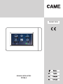
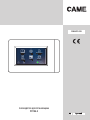
Lista Eventi Mappe Uscite
Scenari Aree Diagnostica
MANUALE INSTALLATORE
PXTS4.3

A
❷
❸
❺
❹
❻
❶
Pag. 2 - Manuale FA00431-IT - ver. 1 - 12/2016- © Came S.p.A. - I contenuti del manuale sono da ritenersi suscettibili di modifica in qualsiasi momento senza obbligo di preavviso.
Avvertenze generali
ATTENZIONE! Importanti istruzioni per la sicurezza delle persone: LEGGERE ATTENTAMENTE!
• L’installazione, la programmazione, la messa in servizio e la manutenzione devono essere eettuate da personale qualificato
ed esperto e nel pieno rispetto delle normative vigenti.
• Indossare indumenti e calzature antistatiche nel caso di intervento sulla scheda elettronica.
• Conservare queste avvertenze.
• Togliere sempre l’alimentazione elettrica durante le operazioni di pulizia o di manutenzione.
• Il prodotto deve essere destinato solo all’uso per il quale è stato espressamente studiato. Ogni altro uso è da considerarsi
pericoloso.
• Il costruttore non può comunque essere considerato responsabile per eventuali danni derivanti da usi impropri, erronei ed
irragionevoli.
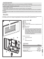
Descrizione
Il terminale 4.3 sicurezza è un terminale che interfacciato alle centrali sicurezza CAME o BPT permette di visualizzare e gestire
lo stato della centrale a cui è collegato. Il collegamento con le centrali avviene tramite il convertitore PXITS4.3.
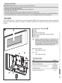
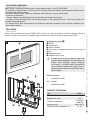
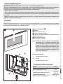
Descrizione delle parti A
❶ Display
❷ Tamper
❸ Morsettiera estraibile
❹ Porta USB per la programmazione o gli aggiornamenti del
software
❺ Supporto metallico
❻ Pulsante di reset
☞Ogni volta che anomalie di funzionamento, interventi
e altre ragioni tecniche richiedono il reset dell’appa-
recchio, premere leggermente il pulsante; rilasciare
il pulsante appena lo schermo si oscura e attendere
che riappaia il menu principale prima di riprendere
l’uso normale dell’apparecchio.
Funzione dei morsetti
+Alimentazione da BUS
A-B Dati
–Alimentazione da BUS
Dati tecnici
Tipo PXTS4.3
Alimentazione (V) 10-15
Assorbimento max (mA) 125
Terminali collegabili (n°) 4 (3 SLAVE,
1 MASTER)
Dimensioni (mm) 166x112x27,3
Temperatura di esercizio (°C) 0 ÷ 40

B C
1
2
F
1
2
G
D E
Pag. 3 - Manuale FA00431-IT - ver. 1 - 12/2016- © Came S.p.A. - I contenuti del manuale sono da ritenersi suscettibili di modifica in qualsiasi momento senza obbligo di preavviso.
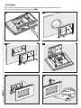
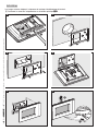
Installazione
Nelle immagini che seguono viene mostrata la sequenza di montaggio e smontaggio del terminale.
Inserire la molla del tamper sul relativo pulsante A❷.

I
J
PXC
PROXINET
CN1
-
+
RX
TX
+
-
A
B
+-
AB+-
AB
H
PXITS4.3
R=150Ω
PXTS4.3
(MASTER)
PXTS4.3
(SLAVE)
R=150Ω
1
2
Pag. 4 - Manuale FA00431-IT - ver. 1 - 12/2016- © Came S.p.A. - I contenuti del manuale sono da ritenersi suscettibili di modifica in qualsiasi momento senza obbligo di preavviso.
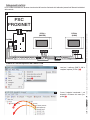
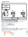
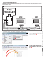
Collegamenti elettrici
Per le caratteristiche del cavo, distanze e terminazioni di linea fare riferimento alle indicazioni presenti nel 'Manuale Installatore'
della centrale.
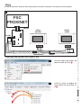
Lanciare il software CAME D SW e
scegliere l'opzione [PXTS4.3] .
Creare l'impianto trascinando i vari
dispositivi all'interno del menu [Im-
pianto] 2.
Creare un nuovo impianto da CAME D SW

K
L
3
4
Pag. 5 - Manuale FA00431-IT - ver. 1 - 12/2016- © Came S.p.A. - I contenuti del manuale sono da ritenersi suscettibili di modifica in qualsiasi momento senza obbligo di preavviso.
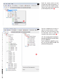
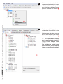
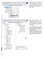
Selezionare la centrale sicurezza, e tra-
mite il tasto destro del mouse, al me-
nu [Carica Configurazione] è possibile
caricare la configurazione completa
dell'impianto antintrusione C.
Caricata la configurazione è visibile la
struttura dell'impianto.
Selezionare uno dei due terminali, dal
menu a tendina, per modificare la
struttura dell'impianto sicurezza 4.
È possibile caricare la configu-
razione solo del terminale sicurezza
PXTS4.3 impostato come MASTER.
Per impostare un terminale come
MASTER oppure SLAVE vedere il
Manuale Utente al menu [Security
Settings].

1
B
C
D
E
M
F
G
N
8
9
O
Pag. 6 - Manuale FA00431-IT - ver. 1 - 12/2016- © Came S.p.A. - I contenuti del manuale sono da ritenersi suscettibili di modifica in qualsiasi momento senza obbligo di preavviso.
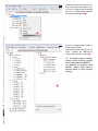
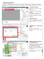
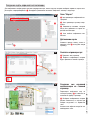
Creare una mappa sicurezza
Per visualizzare la configurazione dell'impianto mediante mappe, dopo aver caricato la configurazione, selezionare il terminale
del quale si desidera programmare la vista a mappe . L'interfaccia del software permette di costruire la vista a mappe.
La finestra mappe
B Area visualizzazioni immagini in-
terfaccia.
C Area visualizzazioni pagine inter-
faccia.
D Elementi dell'impianto che si pos-
sono aggiungere alle mappe sicurezza.
E Area proprietà dell'elemento se-
lezionato.
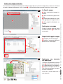
Aggiungere una mappa
Premere il pulsante destro del mouse
all’interno dell’area C e creare una
nuova pagina.
Proprietà della pagina mappe
F Assegnare un nome alla pagina.
G Scegliere l’immagine da abbinare a
quella che sarà la home page.
Aggiungere aree sicurezza
alla home page
Trascinare l'area desiderata sulla home
page 8 e modificare a piacimento for-
ma e dimensione dell'area disponibile.
9 Scegliere l'immagine che deve es-
sere visualizzata toccando l'area appe-
na creata sul terminale.
Creare con lo stesso metodo tutte le
aree necessarie.

K
J
P
Security touch 01 Security touch 02
Q
R
Pag. 7 - Manuale FA00431-IT - ver. 1 - 12/2016- © Came S.p.A. - I contenuti del manuale sono da ritenersi suscettibili di modifica in qualsiasi momento senza obbligo di preavviso.
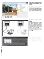
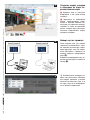
Aggiungere ingressi, uscite e
scenari ad una mappa sicu-
rezza
J Selezionare una delle immagini
disponibili (anche la home page).
K Trascinare all'interno dell'immagine
le icone che rappresentano ingressi,
uscite e scenari sicurezza. Nel termi-
nale esse saranno sostituite da altret-
tante icone che riporteranno lo stato di
ingressi, uscite e scenari visualizzati.
Importare le mappe in un ter-
minale
Una volta generate le viste a mappe
per ognuno dei terminali sicurezza
presenti nell'impianto, è necessario
connettere il proprio PC, mediante cavo
USB, al terminale nel quale si intende
esportare la vista a mappe Q.
Visualizzare la mappa sicurezza che si
intende esportare ed eseguire l'espor-
tazione R.
Le operazioni di importazione de-
scritte devono essere svolte su ognuno
dei terminali presenti nell'impianto. Le
stesse mappe possono essere impor-
tate su più terminali.

Came S.p.A.
Via Martiri Della Libertà, 15 Via Cornia, 1/b - 1/c
31030 Dosson di Casier
Treviso - Italy
33079 Sesto al Reghena
Pordenone - Italy
(+39) 0422 4940
(+39) 0422 4941
(+39) 0434 698111
(+39) 0434 698434
www.came.com
Italiano - Manuale FA00431-IT - ver. 1 - 12/2016 - © Came S.p.A.
I contenuti del manuale sono da ritenersi suscettibili di modifica in qualsiasi momento senza obbligo di preavviso.

FA00431-EN
Event list Maps Outputs
Scenarios Areas Diagnostics
INSTALLER MANUAL
PXTS4.3

A
❷
❸
❺
❹
❻
❶
Page 2 - Manual FA00431-EN - ver. 1 - 12/2016 - © CAME S.p.A. - The contents of this manual are subject to change at any time without prior notice.
Description of the components A
❶ Display
❷ Tamper
❸ Removable terminal block
❹ USB port for programming or software updates
❺ Metal support
❻ Reset button
☞Whenever operating problems, interventions and
other technical reasons require the device to be re-
set, gently press the button. Release the button when
the screen goes blank and wait for the main menu to
reappear before resuming normal device use.
Role of each terminal
+Power supply from BUS
A-B Data
–Power supply from BUS
Technical data
Type PXTS4.3
Power supply (V) 10-15
Max current draw (mA) 125
Terminals that can be connected (n°) 4 (3 SLAVE,
1 MASTER)
Dimensions (mm) 166x112x27.3
Operating temperature (°C) 0 - 40
General warnings
CAUTION! Important personal safety instructions: READ CAREFULLY!
• Installation, programming, commissioning and maintenance must only be performed by qualified and experienced personnel
in compliance with applicable regulations.
• Wear antistatic shoes and clothing if working on the control board.
• Keep hold of these warnings.
• Always disconnect the electrical power supply during cleaning or maintenance.
• This product should only be used for the purpose for which it was explicitly designed. Any other use is considered dangerous.
• The manufacturer declines all liability for any damage as a result of improper, incorrect or unreasonable use.
Description
The 4.3 security terminal is a terminal which, when interfaced with CAME or BPT security control unit, allows you to view and
manage the status of the control unit to which it is connected. Connection to the control units takes place via the PXITS4.3
converter.

B C
1
2
F
1
2
G
D E
Page 3 - Manual FA00431-EN - ver. 1 - 12/2016 - © CAME S.p.A. - The contents of this manual are subject to change at any time without prior notice.
Installation
The images below shows the sequence of assembly and disassembly for the terminal.
Insert the tamper spring on the relative button A❷.

I
J
PXC
PROXINET
CN1
-
+
RX
TX
+
-
A
B
+-
AB+-
AB
H
PXITS4.3
R=150Ω
PXTS4.3
(MASTER)
PXTS4.3
(SLAVE)
R=150Ω
1
2
Page 4 - Manual FA00431-EN - ver. 1 - 12/2016 - © CAME S.p.A. - The contents of this manual are subject to change at any time without prior notice.
Creating a new system from CAME D SW
Create the system by dragging the
various devices into the [System] me-
nu 2.
Launch the CAME D SW software and
choose the option [PXTS4.3] .
Wiring
For cable characteristics, distances and line terminations, please refer to directions in the control unit 'Installer Manual'.

K
L
3
4
Page 5 - Manual FA00431-EN - ver. 1 - 12/2016 - © CAME S.p.A. - The contents of this manual are subject to change at any time without prior notice.
Once the configuration has been lo-
aded, the system structure is visible.
Select one of the two terminals from
the drop-down menu to modify the
structure of the security system 4.
You can only load the configura-
tion from the PXTS4.3 security termi-
nal set as MASTER.
To set a terminal as MASTER or SLA-
VE, see the User Manual under the
[Security Settings] menu.
Select the security control unit and,
using the right-hand mouse button, it is
possible to load the complete configu-
ration of the intruder system under the
[Load Configuration] menu 3.

1
B
C
D
E
M
F
G
N
8
9
O
Page 6 - Manual FA00431-EN - ver. 1 - 12/2016 - © CAME S.p.A. - The contents of this manual are subject to change at any time without prior notice.
Adding security areas to the
home page
Drag the desired area onto the home
page 8 and edit the shape and size of
the area available as required.
9 Choose the image to be displayed
when the newly created area on the
terminal is touched.
Create all the necessary areas using
the same method.
Map page properties
6 Assign a name to the page.
7 Choose the image to combine with
the home page.
The map window
2 Image interface display area
3 Page interface display area
4 System elements that can be added
to the security maps.
5 Selected element property area
Adding a map
Press the right-hand mouse button
inside area 3 and create a new page.
Creating a security map
To view the system configuration using maps, after loading the configuration, select the terminal for which you want to program
the map view . The software interface allows you to build map views.

K
J
P
Security touch 01 Security touch 02
Q
R
Page 7 - Manual FA00431-EN - ver. 1 - 12/2016 - © CAME S.p.A. - The contents of this manual are subject to change at any time without prior notice.
The import operations described
must be carried out on each of the
terminals in the system. The same
maps can be imported into multiple
terminals.
Importing the maps into a
terminal
Once you have generated the map
views for each of the security terminals
in the system, you need to connect
your PC to the terminal to which you
intend to export the map view, via USB
cable Q.
View the security map to be exported
and export it R.
Adding inputs, outputs and
scenarios to a security map
J Select one of the available images
(also the home page).
K Drag the icons representing securi-
ty inputs, outputs and scenarios inside
the image. In the terminal, they will
be replaced by the same number of
icons, showing the status of the inputs,
outputs and scenarios displayed.

Came S.p.A.
Via Martiri Della Libertà, 15 Via Cornia, 1/b - 1/c
31030 Dosson di Casier
Treviso - Italy
33079 Sesto al Reghena
Pordenone - Italy
(+39) 0422 4940
(+39) 0422 4941
(+39) 0434 698111
(+39) 0434 698434
www.came.com
English - Manual FA00431-EN - ver. 1 - 12/2016 - © Came S.p.A.
The contents of this manual are subject to change at any time without prior notice.

FA00431-FR
Liste Événe-
ments Cartes Sorties
Scénarios Zones Diagnostic
MANUEL INSTALLATEUR
PXTS4.3

A
❷
❸
❺
❹
❻
❶
Page 2 - Manuel FA00431-FR - vers. 1 - 12/2016- © Came S.p.A. - Le contenu de ce manuel est susceptible de subir des modifications à tout moment et sans aucun préavis.
Description des parties A
❶ Acheur
❷ Autoprotection
❸ Bornier extractible
❹ Port USB pour la programmation ou les mises à jour du
logiciel
❺ Support métallique
❻ Bouton de remise à zéro
☞À chaque remise à zéro de l’appareil, suite à des
anomalies de fonctionnement, des interventions ou
d’autres raisons techniques, appuyer brièvement
sur le bouton ; le relâcher lorsque la luminosité de
l’écran se réduit et attendre que la page visualise à
nouveau le menu principal avant de réutiliser norma-
lement l’appareil.
Fonction des bornes
+Alimentation par BUS
A-B Données
–Alimentation par BUS
Données techniques
Type PXTS4.3
Alimentation (V) 10-15
Absorption max. (mA) 125
Terminaux connectables 4 (3 SLAVE,
1 MASTER)
Dimensions (mm) 166x112x27,3
Température de fonctionnement (°C) 0 - 40
Instructions générales
ATTENTION ! Instructions importantes pour la sécurité des personnes : À LIRE ATTENTIVEMENT !
• L’installation, la programmation, la mise en service et l'entretien doivent être eectués par du personnel qualifié et dans le
plein respect des normes en vigueur.
• Porter des vêtements et des chaussures antistatiques avant d'intervenir sur la carte électronique.
• Conserver ces instructions.
• Toujours couper le courant électrique durant les opérations de nettoyage ou d'entretien.
• Ce produit ne devra être destiné qu'à l'utilisation pour laquelle il a été expressément conçu. Toute autre utilisation est à
considérer comme dangereuse.
• Le fabricant décline toute responsabilité en cas d'éventuels dommages provoqués par des utilisations impropres, incor-
rectes et déraisonnables.
Description
Interfacé avec les centrales de sécurité CAME ou BPT, le terminal 4.3 sécurité permet de visualiser et de gérer l’état de la
centrale à laquelle il est connecté. La connexion avec les centrales est établie au moyen du convertisseur PXITS4.3.

B C
1
2
F
1
2
G
D E
Page 3 - Manuel FA00431-FR - vers. 1 - 12/2016- © Came S.p.A. - Le contenu de ce manuel est susceptible de subir des modifications à tout moment et sans aucun préavis.
Installation
Les images suivantes indiquent la séquence de montage et de démontage du terminal.
Positionner le ressort de l’autoprotection sur le bouton spécifique A❷.

I
J
PXC
PROXINET
CN1
-
+
RX
TX
+
-
A
B
+-
AB+-
AB
H
PXITS4.3
R=150Ω
PXTS4.3
(MASTER)
PXTS4.3
(SLAVE)
R=150Ω
1
2
Page 4 - Manuel FA00431-FR - vers. 1 - 12/2016- © Came S.p.A. - Le contenu de ce manuel est susceptible de subir des modifications à tout moment et sans aucun préavis.
Créer une nouvelle installation par le biais de CAME D SW
Créer l’installation en faisant glisser
les différents dispositifs dans le menu
[Installation] 2.
Lancer le logiciel CAME D SW et choisir
l’option [PXTS4.3] .
Branchements électriques
Pour les caractéristiques du câble, les distances et les fins de ligne, voir les indications fournies dans le « Manuel Installateur
» de la centrale.
La pagina si sta caricando...
La pagina si sta caricando...
La pagina si sta caricando...
La pagina si sta caricando...
La pagina si sta caricando...
La pagina si sta caricando...
La pagina si sta caricando...
La pagina si sta caricando...
La pagina si sta caricando...
La pagina si sta caricando...
La pagina si sta caricando...
La pagina si sta caricando...
-
 1
1
-
 2
2
-
 3
3
-
 4
4
-
 5
5
-
 6
6
-
 7
7
-
 8
8
-
 9
9
-
 10
10
-
 11
11
-
 12
12
-
 13
13
-
 14
14
-
 15
15
-
 16
16
-
 17
17
-
 18
18
-
 19
19
-
 20
20
-
 21
21
-
 22
22
-
 23
23
-
 24
24
-
 25
25
-
 26
26
-
 27
27
-
 28
28
-
 29
29
-
 30
30
-
 31
31
-
 32
32


Documenti correlati
-
CAME PROXINET Guida d'installazione
-
CAME TS4.3 Guida d'installazione
-
-
-
-
-
-
-
-