Lince 9521-GOLD-TXRX Istruzioni per l'uso
- Tipo
- Istruzioni per l'uso

IT
EN
RICETRASMETTITORE PER SIRENA VIA
RADIO
Manuale di installazione, uso e manutenzione
Installation, operation and maintenance manual
TRANSCEIVER FOR WIRELESS
OUTDOOR SIREN
ART. / ITEM:
9521-GOLD-TXRX
RICETRASMETTITORE
PER SIRENA
VIA RADIO
TRANSCEIVER FOR
WIRELESS OUTDOOR
SIREN
MADE IN ITALY
La dichiarazione CE del presente articolo
è reperibile sul sito www.lince.net.
The CE declaration of this item is available
on www.lince.net website.

2
LINCE ITALIA S.p.A.
- Istruzioni originali -
1. INTRODUZIONE ................................................................................................ 3
1.1 CARATTERISTICHE GENERALI ........................................................... 3
1.2 CARATTERISTICHE TECNICHE ........................................................... 3
1.3 CONTENUTO DELLA CONFEZIONE .................................................... 3
1.4 IDENTIFICAZIONE DELLE PARTI ......................................................... 4
2. INSTALLAZIONE............................................................................................... 4
2.1 MONTAGGIO A MURO .......................................................................... 4
2.2 MONTAGGIO IN CENTRALE ................................................................. 4
2.3 COLLEGAMENTI ELETTRICI ................................................................ 5
2.4 IMPOSTAZIONI ...................................................................................... 5
3. MEMORIZZAZIONE ......................................................................................... 6
3.1 FUNZIONE SLEEP .................................................................................6
4. ESEMPIO DI COLLEGAMENTO.......................................................................6
5. RESET DEL MODULO ....................................................................................7
6. USCITE .............................................................................................................. 7
7. MANUTENZIONE E VERIFICHE PERIODICHE ............................................... 7
8. SMALTIMENTO E ROTTAMAZIONE ................................................................ 7
8.1 DISINSTALLAZIONE .............................................................................. 7
INDICE
- Translation of the original instructions (original instructions in Italian) -
Le informazioni riportate in questo manuale sono state compilate
con cura, tuttavia LINCE ITALIA S.p.A. non può essere ritenuta
responsabile per eventuali errori e/o omissioni. LINCE ITALIA
S.p.A. si riserva il diritto di apportare in ogni momento e senza
preavviso, miglioramenti e/o modiche ai prodotti descritti
nel presente manuale. Consultare il sito www.lince.net per le
condizioni di assistenza e garanzia. LINCE ITALIA S.p.A. pone
particolare attenzione al rispetto dell’ambiente. Tutti i prodotti ed i
processi produttivi sono progettati con criteri di eco-compatibilità.
Il presente articolo è stato prodotto in Italia.
The information in this manual has been issued with care, but
LINCE ITALIA S.p.A. will not be responsible for any errors or
omissions. LINCE ITALIA S.p.A. reserves the right to improve
or modify the products described in this manual at any time
and without advance notice. Terms and conditions regarding
assistance and the product warranty can be found at LINCE
ITALIA’s website www.lince.net. LINCE ITALIA S.p.A. makes it a
priority to respect the environment. All products and production
processes are designed to be eco-friendly and sustainable.
This product has been Made in Italy
1. DESCRIPTION .................................................................................................. 3
1.1 GENERAL FEATURES .......................................................................... 3
1.2 TECHNICAL FEATURES ....................................................................... 3
1.3 PACKAGING CONTENTS ...................................................................... 3
1.4 PARTS IDENTIFICATION.......................................................................4
2. INSTALLATION ................................................................................................. 4
2.1 WALL MOUNTING .................................................................................4
2.2 CONTROL PANEL MOUNTING ............................................................. 4
2.2 ELECTRICAL WIRING ........................................................................... 5
2.4 SETTINGS ............................................................................................. 5
3. STORING ...........................................................................................................6
3.1 SLEEP FUNCTION ................................................................................6
4. EXAMPLE OF CONNECTION ......................................................................... 6
5. MODULE RESET .............................................................................................. 7
6. OUTPUTS .......................................................................................................... 7
7. MAINTENANCE AND PERIODIC CHECKS ..................................................... 7
8. DISPOSAL AND SCRAPPING .......................................................................... 7
8.1 DISMANTLING ....................................................................................... 7
CONTENTS

3
LINCE ITALIA S.p.A.
1.2 CARATTERISTICHE TECNICHE
9521-GOLD-TXRX
Alimentazione
(min-max) 9 ÷ 35 Vcc
Consumo 19 mA @ 13,8 V con tamper chiuso
Frequenza di
esercizio
869,40 ÷ 869,65 MHz 1 canale
868,00 ÷ 868,60 MHz 4 canali
Sicurezza della
trasmissione FH; TDMA; AES
Temperatura di
funzionamento 5 ÷ 40 °C
Dimensioni
contenitore
plastico
30x100x110 mm
Peso 110 g
Peso
(solo scheda) 40 g
1. INTRODUZIONE
Il manuale descrive le modalità di installazione e di impostazione
del ricetrasmettitore per sirena via radio. L’apertura del
coperchio e lo strappo dal muro sono protetti dalla presenza di
un microswitch mentre il funzionamento a sicurezza intrinseca
(allarme per mancanza di positivo o di negativo) protegge
contro il taglio dei cavi. Il ricetrasmettitore dispone di un contatto
normalmente chiuso (NC) per il collegamento con la linea
antisabotaggio delle centrali antifurto.
1.1 CARATTERISTICHE GENERALI
• memorizzazionenoa16sireneviaradio;
• portatanoa1500minarialibera;
• comunicazione bidirezionale tra sirena e modulo TX/RX;
• compatibile con le versioni avanzate delle sirene con
sistema;antischiuma,antiammaegestionealimentazione
WIN3;
• gestione indipendente delle informazioni di “stato batteria”,
“sabotaggio” e “guasto”;
• gestione “stato impianto” ed “esistenza in vita”;
• regolazione volume;
• Controllo portata radio.
1.2 TECHNICAL FEATURES
9521-GOLD-TXRX
Operating voltage
(min-max) 9 ÷ 35 Vdc.
Power
consumption 19 mA @ 13.8 V with tamper cloesd
Operating
frequency
869.40 ÷ 869.65 MHz 1 channel
868.00 ÷ 868.60 MHz 4 channels
Security
transmission FH; TDMA; AES
Operating
temperature 5 ÷ 40 °C
Plastic case
dimensions 30x100x110 mm
Weight 110 g
Weight
(board only) 40 g
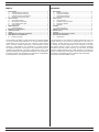
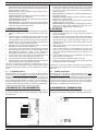
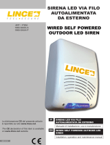
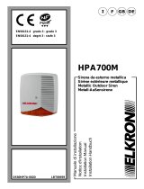
1.3 CONTENUTO DELLA CONFEZIONE 1.3 PACKAGING CONTENTS
Tabella 1
Rif.. Parte
ARicetrasmettitore
BManuale
di istruzioni
C
Piedini adesivi
(all'interno del
prodotto)
Fig. 1
1. DESCRIPTION
The manual describes the installation and the settings of the
transceiver for wireless siren. Opening of the lid and removal
from the wall are protected by a microswitch and intrinsically
safe installation and set-up (alarm for lack of positive or
negative) protects against the wire-cutting. The transceiver has
a normally closed contact (NC) to connect to the control panel
tamper alarm.
1.1 GENERAL FEATURES
• up to 16 sirens storable;
• wireless range up to 1500 m in free air;
• bidirectional communication between siren and TX/RX
module;
• compatible with the advanced versions of sirens provided
with antifoam and ameproof systems and WIN3 supply
managing system;
• indipendent managing of the information of "battery status",
"tamper" and "fail";
• managing of "system status" and "life test" functions;
• volume setting;
• Wireless range check.
Table 1
Ref. Part
ATransceiver
BIstruction
manual
C
Nylon spacers
(Inside the
device)
A
B
C

4
LINCE ITALIA S.p.A.
I
A
B
C
D
G
I
L
E
H
F
L
X Y
M
M
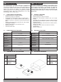
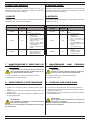
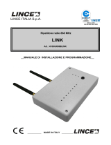
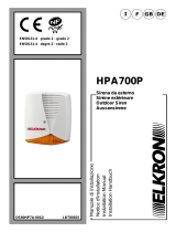
Tabella 2
Rif. Parte
AScheda elettronica
BDip-switch
CMorsettiera
DTrimmer volume
ETasto funzione
F
Jumper per
microswitch antisabotag-
gio
GLED di stato
H
Microswitch antisabo-
taggio e foro antistrappo
(sotto il microswitch)
IForidissaggioalmuro
LPassaggio cavi
MVitidissaggioscheda
1.4 IDENTIFICAZIONE DELLE PARTI
Il ricetrasmettitore può essere installato sia su un muro utilizzando
il contenitore plastico in dotazione, sia all'interno della centrale
ad esso collegata.
2.1 MONTAGGIO A MURO
Per l’installazione a muro procedere come indicato di seguito:
• rimuovere le due viti di chiusura presenti sul coperchio del
contenitore;
• aprire il coperchio;
• con un utensile rimuovere le parti in plastica per il passaggio
dei cavi;
• far passare i cavi di collegamento attraverso l’apposita
apertura dopo aver sfondato il tassello pretagliato (L-Fig.2);
• ssareilsupportoamuroutilizzandoi2fori(I-Fig.2)
• effettuare i collegamenti elettrici come descritti nel paragrafo
2.3;
• riposizionare il coperchio e chiuderlo utilizzando le viti tolte
in precedenza.
NOTA:
Prima di ssare la sirena, vericare la portata radio tramite
il lampeggio del LED (vedi par. 2.4) avendo l'accortezza di
chiudereeventualiporteonestreevericandononditrovarsial
limite della portata radio della sirena.
2.2 MONTAGGIO IN CENTRALE
In alternativa, qualora le condizioni installative lo consentano, è
possibile collocare il ricevitore all'interno della centrale stessa.
Per installare il ricevitore in questo modo, procedere come
indicato di seguito:
• rimuovere le due viti di presenti sul coperchio del contenitore;
2. INSTALLAZIONE
Table 2
Ref. Part
AElectronic board
BDip-switch
CTerminal block
DVolume trimmer
EFunction button
FJumper for anti-tamper
microswitch
GStatus LED
H
Tamper and wall tamper
microswitch and wall
tamper hole (under the
microswitch)
IWallxingslots
LWire passage
MScrewforboardxing
1.4 PARTS IDENTIFICATION
Fig. 2
The transceiver can be placed on a wall by using the plastic case
supplied or inside the control panel to which it is connected
2.1 WALL MOUNTING
For wall mounting proceed as following:
• Remove the two screws placed on the top of the lid;
• open the lid;
• remove the plastic parts of wire passage with a tool;
• route the cables through the passages after breaking the
pre-cut panel (L-Fig.2);
• mount the backplate using the 2 holes (I-Fig.2) ;
• wiring as described in the paragraph 2.3;
• place again the lid by screwing the screws previously
removed.
NOTE:
Before xing the siren, check the wireless range through the
ashing LED (see par. 2.4), be sure to close any doors or
windows and not to be at the limit of the radio range of the siren.
2.2 CONTROL PANEL MOUNTING
When the installation conditions permit, it is possible to place the
receiver inside the control panel itself. To install the receiver in
the above mentioned way, proceed as suggest below:
• Remove the two screws placed on the top of the lid;
NOTA:
Prima di installare le sirene è sempre bene vericare la bontà
del segnale tramite il lampeggio del LED ( vedi par. 2.5). Disturbi
e condizioni ambientali possono alterare la qualità del segnale;
è consigliato dunque effettuare il test ad una distanza superiore
rispetto a quella effettiva di installazione e interponenendo tutti
gli ostacoli che potrebbero presentarsi durante il normale utilizzo
(es.:chiudereporte,nestre,ecc.)
NOTE:
Before installing the sirens it is always advisable to check the
signalgoodnessthroughtheashingoftheLED(seepar.2.5).
Noise and environmental conditions may affect the signal quality;
It is recommended to carry out the test at a higher distance than
the actual installation one and interposing all obstacles that may
arise during normal use (ex.: close doors, windows, etc.)
2. INSTALLATION

5
LINCE ITALIA S.p.A.
2.4 IMPOSTAZIONI
Le indicazioni di seguito riportare permettono di impostare
opportunamente i parametri di tutte le sirene associate al modulo.
Il volume, invece, è possibile aumentarlo ruotando il trimmer
(D-Fig.2) senso orario. Tutte le sirene associate al ricevitore
avranno gli stessi parametri.
Tabella 3 (il default in grassetto)
DIP Funzione OFF ON
X1 Supervisione Disattivo Attivo
X2 LED di segnalazione Disattivi Attivi
X3 Segnalazione portata ra-
dio su uscita "FAULT" Attiva Disattiva
X4 Suono all'inserimento/
disinserimento Disattivo Attivo
X5 Funzioni avanzate Disattive Attive
X6 Tamper sirena Dipendente
dalla centrale
Indipendente
dalla centrale
Y1 Tipo di suono Suono A Suono B
Y2 Cambio frequenza 869 MHz 868-869 MHz
Y3 Partenza allarme Per mancanza
di negativo
Per mancanza
di positivo
Y4 Stato impianto Per mancanza
di negativo
Per mancanza
di positivo
• Supervisione: permette di ricevere un segnale periodico
dalla sirena. Se entro 30 minuti non viene ricevuto questo
segnale, il ricetrasmettitore apre la linea di sabotaggio;
• LED di segnalazione: se abilitato, è attiva sia la
segnalazione del LED rosso di stato (se collegato ST) che
l'esistenza in vita della sirena (con WIN collegato) tramite il
LED blu;
• suono all'inserimento/disinerimento: se abilitato, ad
ogni inserimento/disinserimento la sirena emette un suono
(disponibile solo dalla versione FW 1.30);
• controllo portata radio: il livello di segnale basso tra il
ricevitore e una delle sirene, viene segnalato tramite 5
lampeggi veloci del LED alternati al normale respiro e la
chiusura della linea "FAULT"; se il DIP X3 viene portato in
ON si ha solo la segnalazione tramite LED;
• 12 V : Alimentazione 9 ÷ 35 Vcc;
• LOW BAT: uscita batteria scarica tipo NA;
• FAULT: uscita guasto tipo NA;
• TAMPER: l'uscita di tipo NC, se collegata in centrale,
permette di ricevere informazioni sull'apertura/asportazione
dal muro della scheda ricevente e delle sirene ad essa
associate.
• AL: ingresso di allarme attivabile per mancanza di positivo
omancanzadinegativoinbaseallacongurazionedeiDIP;
• ST: ingresso per la visualizzazione tramite LED dello stato
impianto sulle sirene, selezionabile per mancanza di positivo
o mancanza di negativo.
Appena alimentata la scheda esegue un controllo ambientale
per circa 10 secondi dopo i quali, il LED rosso inizia a "respirare"
indicando lo stato di normale funzionamento (standby).
• aprire il coperchio;
• rimuovere le due viti (M-Fig.2) che tengono la scheda sul
fondo del contenitore;
• collocare la scheda all'interno della centrale e ssarla
utilizzando i due piedini adesivi messi a disposizione.
NOTA: non installare la scheda ricevitore all'interno di contenitori
mettallici al ne di non inciare prestazioni della trasmissione
radio.
2.4 SETTINGS
The instructions below allow to set-up all the parameters of all the
sirens stored on the module. It is possible to increase the siren
volume by turning the trimmer (D-Fig.2) clockwise. All sirens
attached to the receiver will have the same parameters.
Table 3 (deafult in bold)
DIP Function ON OFF (default)
X1 Supervision Disabled Enabled
X2 Signaling LED Disabled Enabled
X3 Wireless range signal on
output "FAULT" Enabled Disabled
X4 Sound on arming/disar-
ming Disabled Enabled
X5 Advanced functions Disabeld Enabled
X6 Siren tamper Dependent from
the control panel
Independent from the
control panel
Y1 Sound type Type A Type B
Y2 Frequency setting 869 MHz 868-869 MHz
Y3 Alarm For lack of
negative
For lack of
positive
Y4 System status For lack of
negative For lack of postive
• Supervision: allows to receive a periodic signal from the
siren. If this signal is not received within a maximum of 30
minutes, the transceiver opens the tamper line;
• signaling LED: if enabled, both the red status LED (if ST
is connected) and the life test of the siren (if WIN terminal
block of the siren is connected) by the blue LED are active;
• sound on arming/disarming: if enabled the siren emits a
sound on each arming or disarming operation, (available
only from FW version 1.30);
• wireless range check: the low signal level between the
receiverandoneofthesirens,issignaledby5quickashes
of the LED alternating normal breath and the closure of the
"FAULT" line, if the X3 DIP is ON there is only the signalling
via LED;
2.3 COLLEGAMENTI ELETTRICI 2.3 ELECTRICAL WIRING
Fig. 3
• 12 V : power supply 9 ÷ 35 Vcc;
• LOW BAT: low battery NO type output;
• FAULT: failure NO type ouput;
• TAMPER: the NC output type, if connected to the control
panel, allows to receive information about the tamper/wall
tamper from the receiver and from all the sirens stored on it;
• AL: input for alarm activated for lack of positive or lack of
negativeaccordingtothecongurationofthedip;
• ST: input to display system status via LEDs on the sirens,
selectable for lack of positive or negative.
As soon as the transceiver has been powered, it performs an
environmental control for about 10 seconds after which the red
LED begins to "breathe" indicating the state of normal operation
(stand-by).
• open the lid;
• remove the two screws (M-Fig.2) that keep the board on the
bottom of the case;
• placetheboardinsidethecontrolpanelandxitbyusing
the two supplied nylon spacers.
NOTE: do not install the transceiver inside metallic case in order
to avoid to affect the wireless transmission.

6
LINCE ITALIA S.p.A.
#1
#16
12V
3 MEMORIZZAZIONE
Per memorizzare le sirene seguire i passi riportati qui di seguito:
1. Premere il tastino per 2 s no ad accensione LED rosso
sso;
2. rilasciare il tasto e attendere il lampeggio veloce del LED
rosso ad indicare l' inizio della fase di ricezione; nel caso
sia stato appena fatto il reset del modulo sarà necessario
attenderenoa15secondiperillampeggiodelLEDrosso
duranteiquali,lostessosaràaccesosso;
3. alimentare la sirena da memorizzare e entro 10 secondi
premere per tre volte il tamper della sirena;
4. se il modulo riceve una trama di memorizzazione corretta il
LED rosso rimane acceso per 40 s a conferma dell'avvenuta
memorizzazione terminati i quali, il LED comincia a
lampeggiare(l'acqusizionepuòdurarenoa40secondi);
5. se il modulo riceve una trama di memorizzazione non
corretta il LED rosso lampeggia velocemente per 5 s;
6. per memorizzare altre sirene ripetere i passi da 3 a 5;
7. premere il tastino per uscire dalla memorizzazione ed inviare
le impostazioni a tutte le sirene radio associate.
Nel caso sia necessario modicare i parametri dopo che le
sirene sono state memorizzate, premere brevemente il tastino
di memorizzazione per inviare le nuove impostazioni a tutte le
sirene.
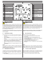
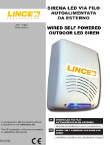
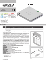
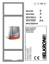
4 ESEMPIO DI COLLEGAMENTO
Nell'esempio riportato di seguito vengono illustrati gli ingressi e
le uscite necessarie per un corretto collegamento della scheda
ricetrasmittente.
3.1 FUNZIONE SLEEP
Questa funzione pone la sirena in uno stato dormiente a basso
consumo (in cui non trasmette e non riceve) nel caso in cui
ricevitore e sirene siano fuori portata per oltre 15 minuti, per
esempio, a causa della rimozione del modulo ricetrasmettitore
per un'eventuale manutenzione. La sirena una volta entrata in
questa modalità si riattiva dopo un'ora per un minuto, controllando
la presenza della trama del modulo e, qualora non sia presente,
rientrainunostatodormientenoall'orasuccessiva.
3.1 SLEEP FUNCTION
This function puts the siren in a sleepy low-power state (where
not transmitting or receiving) if receiver and sirens go out of
range for over 15 minutes, for example, due to the removal of
the wireless transceiver module for eventual maintenance. Once
the siren enters this mode, it wakes up for a minute for checking
the presence of messages from the module and, if not present,
falls again into a sleepy state until the next hour.
• funzioni avanzate (antischiumaeantiamma): riferirsi alla
sirena utilizzata. Se ad uno stesso ricevitore sono associate
sirene con e senza funzioni avanzate, seguiranno tutte la
programmazione del DIP X5;
• tipo di suono: si può scegliere il tipo di suono che si
preferisce (lento o veloce);
• cambio frequenza: possibilità di impostare il sistema in
doppia frequenza o solo a 869 MHz;
• partenza allarme: selezionare in base al tipo di uscita che
viene fornita dalla centrale;
• Stato impianto: lo stato impianto viene visualizzato tramite
il LED posizionato sulla sirena; selezionare in base al tipo di
uscita che viene fornita dalla centrale
• advanced functions (antifoam and ameproof): please
refear to the installation manual of the siren in use. Please
consider that if sirens with and without advanced functions
are stored on the same receiver, they will all follow the
setting of X5 DIP;
• type of sound: it is possible to choose the preferred type of
sound (slow or fast);
• frequency setting: possibility to set the to system in double
frequency or only in 869 MHz;
• alarm: to be selected accordinf to the type of output that is
supplied from the control panel;
• System status: the system status is dysplayed by the LED
placed on the siren; select depending on the type of the
output that is supplied from the control panel.
3 STORING
To storing of the sirens follows the steps reported below:
1. Press the function button for 2 seconds untill the red LED
turnsonandxed;
2. releasethebuttonandwaitforthequickashofredLEDto
signalling the start of the storage step; in case the module
has just been reset, it will be necessary to wait up to 15
seconds for the red LED to ash, during which it will be
permanently on;
3. supply the siren to be stored and press for three times the
siren tamper switch;
4. if the module receives a valid transmission the red LED
stays on for 40 seconds as conrmation of storage, after
which,theLEDbegins ashing(storingcantakeup to40
seconds);
5. if the module receives a bad transmission, the red LED
ashesquicklyfor5seconds;
6. to store other sirens, repeat the steps from 3 to 5;
7. press the function button to go out from the storing and send
the settings to all the stored sirens.
If necessary, modify the settings after the storings procedure,
press shortly the function button to send the new settings to all
the sirens.
4 EXAMPLE OF CONNECTION
In the example below are illustrated the inputs and otuputs
necessary for the proper management of the transceiver board.
Fig. 4

7
LINCE ITALIA S.p.A.
5 RESET DEL MODULO
Durante la fase di stand-by, premere il tastino per oltre 10 s
aspettando che il LED da rosso sso si spenga, per portare il
modulo alle impostazioni di fabbrica.
7 MANUTENZIONE E VERIFICHE PE-
RIODICHE
ATTENZIONE! Per rimuovere sporcizie particolar-
mente evidenti NON utilizzare prodotti a base di clo-
ro, prodotti abrasivi oppure alcool.
1. Pulire il coperchio con un panno inumidito con acqua.
2. Ripassare con un panno asciutto.
8 SMALTIMENTO E ROTTAMAZIONE
1. Svitarelevitichetengonossoilcoperchiofrontaleerimuo-
verlo.
2. Scollegare la scheda: sulla morsettiera scollegare tutti i mor-
setti (v. Fig. 3).
3. Dividere le parti in base alla loro tipologia e smaltirle in accor-
do con le leggi vigenti.
ATTENZIONE!
Non disperdere nell’ambiente i componenti ed ogni
altro materiale del prodotto.
Rivolgersi a consorzi abilitati allo smaltimento ed al riciclag-
gio dei materiali.
6 USCITE
Di seguito viene riportato lo stato di default delle uscite e le
informazioni che ognuna di essere riporta.
Tabella 4
MORSETTO TIPO DI
USCITA INFORMAZIONI
LOW BAT N.A. Batteria primaria o secondaria
scarica
FAULT N.A.
• Guasto antischiuma.
• Guasto LED.
• Guasto speaker.
• Errore connessione con
doppia batteria 9 V as-
sieme a 12 V Pb.
• Tensione WIN bassa
(<11V) solo se è connes-
sa la batteria Pb.
• Livello di segnale radio
basso.
TAMPER N.C.
• Tamper.
• Allarme supervisione.
• Allarmeantiamma.
• Allarme antischiuma.
5 MODULE RESET
During the stand-by mode, press the button for over 10 seconds
andwaituntiltheredLEDbecamexandthenturnsofftobring
the module to the factory settings.
7 MAINTENANCE AND PERIODIC
CHECKS
IMPORTANT!
Do NOT use chlorine-based or abrasive products or
alcohol to remove particularly noticeable dirt.
1. Clean the lid with a cloth dampened with water.
2. Wipe with a dry cloth.
8 DISPOSAL AND SCRAPPING
1. Unscrew the screws that fasten the front lid and remove it.
2. Disconnect the board: disconnect all the terminals on the ter-
minal block (see Fig. 3).
3. Divide the parts by type and dispose of them in accordance
with applicable laws.
IMPORTANT!
Do not dispose of the components or any other ma-
terial in the environment.
Seek the assistance of companies authorised to dispose of
and recycle waste materials.
6 OUTPUTS
The following table reports the type of output and the information
related each output.
Table 4
TERMINAL
BLOCK
TYPE OF
OUTPUT INFO
LOW BAT N.O. Primary or secondary battery
status
FAULT N.O.
• Anti-foam failure.
• LED failure.
• Speaker failure.
• Error for connection of
both 9 V and 12 V Pb
batteries.
• Low WIN voltage (<11 V)
only if Pb battery is con-
nected.
• Low wireless signal
TAMPER N.C.
• Tamper.
• Supervision alarm.
• Flameproof alarm.
• Anti-foam alarm.

001530/00870AG Rev0
LINCE ITALIA S.p.A
Via Variante di Cancelliera, snc
00072 ARICCIA (Roma)
Tel. +39 06 9301801
Fax +39 06 930180232
www.lince.net
-
 1
1
-
 2
2
-
 3
3
-
 4
4
-
 5
5
-
 6
6
-
 7
7
-
 8
8


Lince 9521-GOLD-TXRX Istruzioni per l'uso
- Tipo
- Istruzioni per l'uso
in altre lingue
Documenti correlati
-
 Lince OBLO'/E Istruzioni per l'uso
-
 Lince 1938-SAXA-E Istruzioni per l'uso
-
 Lince 9560-GOLD-SAXA Istruzioni per l'uso
-
 Lince 1964-SAXA-A Istruzioni per l'uso
-
 Lince 9518-GOLD-OBLO/L Istruzioni per l'uso
-
 Lince 9557-GOLD-OUT Istruzioni per l'uso
-
 Lince 1943-ONDA4-A Istruzioni per l'uso
-
 Lince 4100GR868LINK Istruzioni per l'uso
-
 Lince 9582-GOLD-MST-E-EN Istruzioni per l'uso
-
 Lince 410LESW Istruzioni per l'uso


Altri documenti
-
 Elkron HPA800 Guida d'installazione
-
 Elkron HPA700M Guida d'installazione
-
 Elkron HPA700P Guida d'installazione
-
CAME PROXINET Manuale del proprietario
-
CAME ADD-ON CP Manuale del proprietario
-
 Elkron KIT MP508TG/FC/IRA Guida d'installazione
-
-
-


