

La ditta costruttrice declina ogni responsabilità per le inesattezze contenute nel presente, se dovute ad errori di
stampa o di trascrizioni.
The manufacturer declines all responsibility for any inaccuracies in this manual due to printing or typing errors.
Gentile cliente,
La ringraziamo per aver preferito nell'acquisto un climatizzatore FERROLI. Esso è frutto di pluriennali esperienze e di
particolari studi di progettazione, ed è stato costruito con materiali di primissima scelta e con tecnologie
avanzatissime.La marcatura CE, inoltre, garantisce che gli apparecchi rispondano ai requisiti della Direttiva Macchi-
ne Europea in materia di sicurezza.Il livello qualitativo è sotto costante sorveglianza, ed i prodotti FERROLI sono
pertanto sinonimo di Sicurezza, Qualità e Afdabilità.Il nostro Servizio di Assistenza più vicino, se non conosciuto,
può essere richiesto al Concessionario presso cui l'apparecchio è stato acquistato, o può essere reperito sulle Pagi-
ne Gialle sotto la voce "Condizionamento" o "Caldaie a gas" (valido solo per il mercato italiano). I dati possono subire
modiche ritenute necessarie per il miglioramento del prodotto.
Nuovamente grazie.
FERROLI S.p.A
Dear Customer,
Thank you for having purchased a FERROLI Idustrial coolers. It is the result of many years experience, particular
research and has been made with top quality materials and higlly advanced technologies. The CE mark guaranteed
thats the appliances meets European Machine Directive requirements regarding safety. The qualitative level is kept
under constant surveillance. FERROLI products therefore offer SAFETY, QUALITY and RELIABILITY.Due to the con-
tinuous improvements in technologies and materials, the product specication as well as performances are subject
to variations without prior notice.
Thank you once again for your preference.
FERROLI S.p.A

3
SOMMARIO
MESSA IN FUNZIONE........................................................................4
RICEVIMENTO..........................................................................4
PREMESSA ............................................................................4
Direttive europee.........................................................................4
TASTI FUNZIONI E DISPLAY...............................................................5
USO DEL TELECOMANDO ................................................................6
ACCENSIONE DELL’UNITA’................................................................6
INSERIMENTO/SOSTITUZIONE DELLE BATTERIE.............................................7
MODALITA’ DI FUNZIONAMENTO...........................................................7
REGOLAZIONE DELLA TEMPERATURA .....................................................7
SCELTA DELLA VELOCITA’ DEL VENTILATORE ...............................................8
FUNZIONAMENTO SLEEP ................................................................8
REGOLAZIONE DELL’USCITA DELL’ARIA ....................................................8
PROGRAMMAZIONE DELL’OROLOGIO ......................................................8
PROGRAMMAZIONE DEL TIMER ...........................................................8
TASTO DI EMERGENZA ..................................................................9
FUNZIONE AUTO-RESTART . . . . . . . . . . . . . . . . . . . . . . . . . . . . . . . . . . . . . . . . . . . . . . . . . . . . . . . . . . . . . . .9
SPEGNIMENTO E MESSA A RIPOSO........................................................9
INDICATORI LED UNITA’ ..................................................................9
VISUALIZZAZIONE ERRORI ...............................................................10
MANUTENZIONE............................................................................10
PULIZIA FILTRI .........................................................................10
PULIZIA DELL'UNITÀ ....................................................................10

4
MESSA IN FUNZIONE
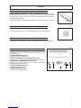
PREMESSA
Il condizionatore è una macchina progettata e costruita esclusivamente per la climatizzazione e deve essere usata
solo per tale scopo. La macchina può funzionare bene e lavorare con profitto soltanto se usata correttamente e
mantenuta in piena efficienza. Preghiamo perciò di leggere attentamente questo libretto d'istruzioni e di rileggerlo
ogni qualvolta, nell'usare l'unità, sorgeranno delle difficoltà o dei dubbi. In caso di necessità ricordiamo comunque
che il nostro servizio d'assistenza, organizzato in collaborazione con i nostri concessionari, è sempre a disposizione
per eventuali consigli e interventi diretti.
DIRETTIVE EUROPEE
L'azienda dichiara che la macchina in oggetto è conforme a quanto prescritto dalle seguenti direttive e successive
modificazioni :
• Direttiva bassa tensione 2006/95/CE;
• Direttiva compatibilità elettromagnetica 2004/104/CE;
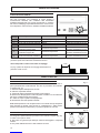
RICEVIMENTO
Al momento del ricevimento dell'unità è indispensabile controllare di aver ricevuto tutto il materiale indicato sul
documento d'accompagnamento, ed inoltre che la stessa non abbia subito danni durante il trasporto. In caso
affermativo, far costatare allo spedizioniere l'entità del danno subito, avvertendo nel frattempo il nostro ufcio
gestione clienti. Soltanto agendo in questo modo e tempestivamente sarà possibile avere il materiale mancante
o il risarcimento dei danni.

5
MESSA IN FUNZIONE
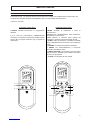
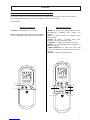
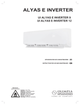
Il telecomando (Fig. 1) è composto da una serie di tasti e da un display che visualizza tutte le funzioni attive ed i
vari parametri necessari all’utente ed all’installatore per un corretto utilizzo dell’unità stessa.
I tasti sono i seguenti:
TASTI FUNZIONI E DISPLAY
A sportello chiuso (Fig.1)
1.ON/OFF: Permette l’accensione e lo spegnimento
dell’unità.
2 e 3: Tasti per l’impostazione "TEMPERATURA
consentono di regolare la temperatura ambiente della
stanza: (▲) ne imposta l'aumento, (▼) ne imposta la
diminuzione.
.
A sportello aperto (Fig.2)
1.MODE: Permette di selezionare il modo di
funzionamento:
Raffreddamento, Deumidificazione, Sola Ventilazione,
Riscaldamento e Automatico.
2.FAN: Pulsante di selezione della velocità del
ventilatore o di selezione automatica della velocità.
3. SLEEP: Usato per impostare / cancellare la modalità
Sleep, indipendentemente dal modo in cui sta operando
l’unità.
4. LOUVER: Per cambiare la posizione dell’aletta.
5. SWING: Per attivare/disattivare il movimento
automatico del deflettore d’aria.
6. TIMER FUNCTION: Per impostare la funzione Timer
(ON) accensione, (CANCEL) per annullare la funzione
(OFF) per lo spegnimento.
7. CLOCK: Per impostare gli orari richiesti.
AUTO
FAN
ON
CANCEL OFF
MODE
SLEEP LOUVER
SWING
TIMER FUNCTION
23
18:88
AM
PM OFF
ON
°C
AUTO
23
18:88
AM
PM OFF
ON
°C
AUTO
FAN
ON
CANCEL OFF
MODE
SLEEP LOUVER
SWING
TIMER FUNCTION
23
18:88
AM
PM OFF
ON
°C
AUTO
23
18:88
AM
PM OFF
ON
°C
AUTO
FAN
ON
CANCEL OFF
MODE
SLEEP LOUVER
SWING
TIMER FUNCTION
23
18:88
AM
PM OFF
ON
°C
AUTO
23
18:88
AM
PM OFF
ON
°C
1
2
3
1
2
67
5
4
3

6
MESSA IN FUNZIONE
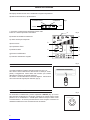
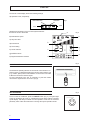
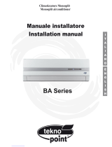
Dal display del telecomando sono visualizzate le seguenti impostazioni:
-a) Modo di funzionamento, rispettivamente
L’ accensione contemporanea del simbolo freddo caldo
indica che l’unità è impostata in Automatico
-b) Velocità del ventilatore selezionata.
-c) Valore del Set point impostato
-d) Ora corrente
-e) Impostazione Timer
-f) Indicatore alette
-g) Funzione SLEEP attiva
-h) Indicatore trasmissione segnale
caldo
ventilazionedeumidificazione
freddo
AUTO
FAN
ON
CANCEL OFF
MODE SLEEP LOUVER
SWING
TIMER FUNCTION
23
18
:
88
AM
PM OFF
ON
°C
AUTO
23
18:88
AM
PM OFF
ON
°C
h
g
f
e
d
c
b
a
AUTO
FAN
ON
CANCEL OFF
MODE
SLEEP LOUVER
SWING
TIMER FUNCTION
23
18:88
AM
PM OFF
ON
°C
AUTO
23
18:88
AM
PM OFF
ON
°C
USO DEL TELECOMANDO
AUTO
FAN
ON
CANCEL OFF
MODE
SLEEP LOUVER
SWING
TIMER FUNCTION
23
18:88
AM
PM OFF
ON
°C
AUTO
23
18:88
AM
PM OFF
ON
°C
AUTO
FAN
ON
CANCEL OFF
MODE
SLEEP LOUVER
SWING
TIMER FUNCTION
23
18:88
AM
PM OFF
ON
°C
AUTO
23
18:88
AM
PM OFF
ON
°C
AUTO
FAN
ON
CANCEL OFF
MODE
SLEEP LOUVER
SWING
TIMER FUNCTION
23
18:88
AM
PM OFF
ON
°C
AUTO
23
18:88
AM
PM OFF
ON
°C
ACCENSIONE DELL’UNITA’
Fig.1
Fig.2
Fig.3
Fig.4
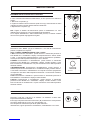
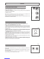
La massima distanza operativa del telecomando è di circa 7 m.
Non devono esserci ostacoli tra il telecomando e l’unità (es. tende,
piante). L’irraggiamento solare diretto del ricevitore può rendere
difficoltosa la ricezione del segnale infrarosso.
Per inviare i comandi all’unità è necessario dirigere il telecomando
verso il ricevitore di segnali posto sull’unità, (Fig.3).
Per accendere il condizionatore, premere il pulsante di ON/OFF (Fig. 4). La luce-
spia verde del condizionatore si accenderà, indicando che è stato avviato. Tenete
presente che il visualizzatore a cristalli liquidi indicherà sempre l'ultimo modo
di funzionamento e le funzioni precedentemente usate. Seguite le istruzioni se
desiderate modificare il modo di funzionamento del sistema.

7
MESSA IN FUNZIONE
AUTO
FAN
ON
CANCEL OFF
MODE
SLEEP LOUVER
SWING
TIMER FUNCTION
23
18:88
AM
PM OFF
ON
°C
AUTO
23
18:88
AM
PM OFF
ON
°C
AUTO
FAN
ON
CANCEL OFF
MODE
SLEEP LOUVER
SWING
TIMER FUNCTION
23
18:88
AM
PM OFF
ON
°C
AUTO
23
18:88
AM
PM OFF
ON
°C
INSERIMENTO/SOSTITUZIONE DELLE BATTERIE
MODALITA’ DI FUNZIONAMENTO
REGOLAZIONE DELLA TEMPERATURA
Premendo il tasto “MODE” (Fig.6) si selezionano i vari modi di funzionamento
preferito, scegliendo tra i seguenti:
AUTO - FREDDO- DEUMIDIFICAZIONE - FAN - CALDO.
1.AUTO Funzionamento Automatico: questa funzione è selezionata premendo il
tasto MODE fino a visualizzare a display contemporaneamente il simbolo freddo
e caldo. L unità imposta automaticamente il modo di funzionamento (FREDDO-
CALDO) in base alla temperatura dell’acqua in arrivo all’unità.
2.FREDDO Funzionamento in raffreddamento: questa funzione è selezionata
premendo il tasto MODE fino a visualizzare a display il relativo simbolo. L’unità
inizia a funzionare in raffreddamento e si porta velocemente vicino alla temperatura
ambiente richiesta.
3.DEUMIDIFICAZIONE Funzionamento deumidificazione: questa funzione è
selezionata premendo il tasto MODE fino a visualizzare a display il relativo simbolo.
L’unità inizia a funzionare in raffreddamento con tempi di accensione spegnimento
che dipendono dal valore della temperatura ambientale. La velocità del ventilatore
non è modificabile.
4.FAN Funzionamento ventilazione: questa funzione è selezionata premendo il
tasto MODE fino a visualizzare a display il relativo simbolo.
5.CALDO Funzionamento in riscaldamento: questa funzione è selezionata
premendo il tasto MODE fino a visualizzare a display il relativo simbolo. L’unità
inizia a funzionare in riscaldamento e si porta velocemente vicino alla temperatura
ambiente richiesta.
Fig.5
1
2
3
Fig.6
Fig.7
In caso di inserimento/sostituzione delle batterie, si deve operare come indicato in
seguito:
1. Rimuovere il coperchio (1).
2. Togliere le batterie scariche ed inserire quelle nuove (2), assicurandosi che siano
collocate secondo lo schema riportato all’interno della sede.
3. Riposizionare il coperchio (3).
N.B.: Togliere le batterie dal telecomando quando il climatizzatore non viene
utilizzato per lunghi periodi, e porle fuori dalla portata dei bambini.
Per il rispetto dell’ambiente e dell’incolumità delle persone, le batterie sostituite
devono essere gettate negli appositi raccoglitori.
Premendo i tasti (▲) e (▼) (Fig 7) si aumenta o si diminuisce il valore della
temperatura desiderata in ambiente.
Il tasto (▲) ne imposta l’aumento mentre il tasto (▼) la diminuzione. La temperatura
può essere selezionata tra 10°C e 35°C ad intervalli di 1°C.
Se la temperatura selezionata è più alta di quella ambiente in
raffrescamento, oppure più bassa in riscaldamento, il climatizzatore non si avvia.

8
MESSA IN FUNZIONE
AUTO
FAN
ON
CANCEL OFF
MODE
SLEEP LOUVER
SWING
TIMER FUNCTION
23
18:88
AM
PM OFF
ON
°C
AUTO
23
18:88
AM
PM OFF
ON
°C
AUTO
FAN
ON
CANCEL OFF
MODE SLEEP LOUVER
SWING
TIMER FUNCTION
23
18:88
AM
PM OFF
ON
°C
AUTO
23
18:88
AM
PM OFF
ON
°C
AUTO
FAN
ON
CANCEL OFF
MODE
SLEEP LOUVER
SWING
TIMER FUNCTION
23
18:88
AM
PM OFF
ON
°C
AUTO
23
18:88
AM
PM OFF
ON
°C
AUTO
FAN
ON
CANCEL OFF
MODE SLEEP LOUVER
SWING
TIMER FUNCTION
23
18:88
AM
PM OFF
ON
°C
AUTO
23
18:88
AM
PM OFF
ON
°C
AUTO
FAN
ON
CANCEL OFF
MODE
SLEEP LOUVER
SWING
TIMER FUNCTION
23
18:88
AM
PM OFF
ON
°C
AUTO
23
18:88
AM
PM OFF
ON
°C
SCELTA DELLA VELOCITA’ DEL VENTILATORE
FUNZIONAMENTO SLEEP
REGOLAZIONE DELL’USCITA DELL’ARIA
PROGRAMMAZIONE DELL’OROLOGIO
PROGRAMMAZIONE DEL TIMER
(Nel funzionamento Automatico la velocità viene regolata automaticamente
per un migliore confort).
23
23 23 23
°C
°F
COOL
SUN
FAN
AUTO
DRY HEAT SLEEP SWING
%
Z
ZZ
MON TUE WED
IR
ON
OFF
TIMER
TIME
PARAMETERS
CANCEL
MODE
FAN
SLEEP FRESHNET
SWING
DAY
THU FRI SAT HEATER
ERR
UNIT
:
23
23 23 23
°C
°F
COOL
SUN
FAN
AUTO
DRY HEAT SLEEP SWING
%
Z
ZZ
MON TUE WED
IR
ON
OFF
TIMER
CANCEL
MODE
FAN
SLEEP FRESHNET
SWING
DAY
THU FRI SAT HEATER
ERR
UNIT
:
23
23 23 23
°C
°F
COOL
SUN
FAN
AUTO
DRY HEAT SLEEP SWING
%
Z
ZZ
MON TUE WED
IR
ON
OFF
THU FRI SAT HEATER
ERR
UNIT
:
TIME
PARAMETERS
23
23 23 23
°C
°F
COOL
SUN
FAN
AUTO
DRY HEAT SLEEP SWING
%
Z
ZZ
MON TUE WED
IR
ON
OFF
TIMER
TIME
PARAMETERS
CANCEL
MODE
FAN
SLEEP FRESHNET
SWING
DAY
THU FRI SAT HEATER
ERR
UNIT
:
23
23 23 23
°C
°F
COOL
SUN
FAN
AUTO
DRY HEAT SLEEP SWING
%
Z
ZZ
MON TUE WED
IR
ON
OFF
TIMER
CANCEL
MODE
FAN
SLEEP FRESHNET
SWING
DAY
THU FRI SAT HEATER
ERR
UNIT
:
23
23 23 23
°C
°F
COOL
SUN
FAN
AUTO
DRY HEAT SLEEP SWING
%
Z
ZZ
MON TUE WED
IR
ON
OFF
THU FRI SAT HEATER
ERR
UNIT
:
TIME
PARAMETERS
23
23 23 23
°C
°F
COOL
SUN
FAN
AUTO
DRY HEAT SLEEP SWING
%
Z
ZZ
MON TUE WED
IR
ON
OFF
TIMER
TIME
PARAMETERS
CANCEL
MODE
FAN
SLEEP FRESHNET
SWING
DAY
THU FRI SAT HEATER
ERR
UNIT
:
23
23 23 23
°C
°F
COOL
SUN
FAN
AUTO
DRY HEAT SLEEP SWING
%
Z
ZZ
MON TUE WED
IR
ON
OFF
TIMER
CANCEL
MODE
FAN
SLEEP FRESHNET
SWING
DAY
THU FRI SAT HEATER
ERR
UNIT
:
23
23 23 23
°C
°F
COOL
SUN
FAN
AUTO
DRY HEAT SLEEP SWING
%
Z
ZZ
MON TUE WED
IR
ON
OFF
THU FRI SAT HEATER
ERR
UNIT
:
TIME
PARAMETERS
23
23 23 23
°C
°F
COOL
SUN
FAN
AUTO
DRY HEAT SLEEP SWING
%
Z
ZZ
MON TUE WED
IR
ON
OFF
TIMER
TIME
PARAMETERS
CANCEL
MODE
FAN
SLEEP FRESHNET
SWING
DAY
THU FRI SAT HEATER
ERR
UNIT
:
23
23 23 23
°C
°F
COOL
SUN
FAN
AUTO
DRY HEAT SLEEP SWING
%
Z
ZZ
MON TUE WED
IR
ON
OFF
TIMER
CANCEL
MODE
FAN
SLEEP FRESHNET
SWING
DAY
THU FRI SAT HEATER
ERR
UNIT
:
23
23 23 23
°C
°F
COOL
SUN
FAN
AUTO
DRY HEAT SLEEP SWING
%
Z
ZZ
MON TUE WED
IR
ON
OFF
THU FRI SAT HEATER
ERR
UNIT
:
TIME
PARAMETERS
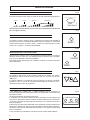
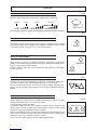
minima media massima automatica
Fig.8
Fig.9
Fig.10
Fig.11
Fig.12
Premendo il pulsante "FAN" (Fig.8) si sceglie la velocità desiderata rispettivamente:
La pressione del tasto “SLEEP” (Fig.9), predispone la macchina nella modalità di
funzionamento notturno evidenziato dal relativo simbolo sul display. La temperatura
aumenta (funzionamento in freddo “COOL”), o diminuisce (funzionamento in caldo
“HEAT”), di 0,5 oppure 1 °C ad intervalli prestabiliti.
All’accensione il deflettore assume un’angolazione predeterminata. Per regolare la
direzione del flusso d’aria che esce dall’unità interna premere il tasto “LOUVER”
(Fig.10). Sono disponibili 4 posizioni prestabilite.
Premendolo il tasto “SWING”(Fig.10), il deflettore continua a muoversi miscelando
l’aria nell’ambiente.
La regolazione dell’orologio va fatta quando le batterie sono inserite. Per attivare
l’impostazione dell’ora corrente tenere premuto per due secondi uno dei tasi
▼▲(Fig.11).
Il comando visualizza l ‘ora impostata. Tenendo premuto uno dei tasti è possibile
regolazione l’ora. La velocità di scorrimento dell’ora dipende dal tempo in cui è
mantenuto premuto il tasto di regolazione.
I tasti TIMER ON e TIMER OFF e TIMER CANCEL (Fig.12) consentono di
impostare rispettivamente l’orario di accensione, di spegnimento o di annullare ogni
impostazione oraria.
Per la programmazione procedere come segue.
1- Premendo una volta il tasto TIMER ON viene visualizzato l’orario impostato per
l’accensione. Mantenendo premuto il tasto è possibile modificare tale impostazione.
La velocità di scorrimento dell’ora dipende dal tempo in cui è mantenuto premuto il
tasto di regolazione.
2- Premendo una volta il tasto TIMER OFF viene visualizzato l’orario impostato per lo
spegnimento. Mantenendo premuto il tasto è possibile modificare tale impostazione.
La velocità di scorrimento dell’ora dipende dal tempo in cui è mantenuto premuto il
tasto di regolazione.
3- Per cancellare ogni impostazione del Timer premere il tasto TIMER CANCEL.

9
MESSA IN FUNZIONE
TASTO DI EMERGENZA
1
FUNZIONE AUTO-RESTART
AUTO
FAN
ON
CANCEL OFF
MODE
SLEEP LOUVER
SWING
TIMER FUNCTION
23
18:88
AM
PM OFF
ON
°C
AUTO
23
18:88
AM
PM OFF
ON
°C
Fig.13
Fig.14
Permette il funzionamento di emergenza in caso di rottura o smarrimento del
telecomando. Mediante pressione ripetuta del pulsante è possibile impostare
le seguenti modalità di funzionamento: Freddo, Caldo, OFF. In entrambi i casi il
set point viene automaticamente selezionato dall’unità cosi come la velocità del
ventilatore verrà scelta dall’unità.
Il bottone Emergenza ON/OFF è su angolo in alto a destra sotto al pannello (1
Fig.13).
L’unità è programmata per accendersi automaticamente in caso di interruzione di
corrente elettrica.
SPEGNIMENTO E MESSA A RIPOSO
Per spegnere l’unità basta premere il tasto di "ON/OFF" (Fig. 14) sul comando.
INDICATORI LED UNITA’
1 2 3 4 5
AUTO
FAN
ON
CANCEL OFF
MODE
SLEEP LOUVER
SWING
TIMER FUNCTION
23
18:88
AM
PM OFF
ON
°C
AUTO
23
18:88
AM
PM OFF
ON
°C
Di seguito viene descritto il significato dei LED situati nel pannello
frontale dell’unità interna:
1. INDICATORE POWER (verde)
Si illumina di quando l’unità è alimentata.
2. INDICATORE PROTEZIONI ATTIVE (rosso)
Si illumina quando sono attive alcune protezioni o allarmi.
3. INDICATORE TEMPERATURA e RICEVITORE
Indica la temperatura impostata ambiente il ricevitore riceve i
segnali dal telecomando
4. INDICATORE MODALITA’ATTIVA (verde)
Si illumina di quando l’unità è in funzione.
5. INDICATORE TIMER (giallo)
Si illumina quando è attivo il TIMER.
Fig.15

10
MESSA IN FUNZIONE
* alcuni allarmi potrebbero essere generati da una carente manutenzione ordinaria. Si raccomanda di eseguire tale
procedura prima di far intervenire l’Assistenza Tecnica.
Come interpretare il numero associato ai lampeggi.
La (Fig. 2) indica la sequenza di 3 lampiggi distanziati da un
periodo di sosta di 3 sec.
N°
lampeggi Tipo di errore Note Azioni*
1 Errore sulla resistenza elettrica Allarme ( non previsto per queste unità) \
2 Errore sulla sonda batteria T2 Allarme( non previsto per queste unità) \
3 Errore sulla sonda aria ambiente Allarme Chiamare l’assistenza tecnica
4 Errore sulla sonda batteria T1 Allarme Chiamare l’assistenza tecnica
5Protezione per temperatura
scambiatore troppo bassa Protezione temporanea Se l’allarme non scompare
chiamare l’assistenza tecnica
6Protezione per temperatura
scambiatore troppo alta Protezione temporanea Se l’allarme non scompare
chiamare l’assistenza tecnica
9 Errore sul motore del ventilatore Protezione temporanea Se l’allarme non scompare
chiamare l’assistenza tecnica
3 sec
VISUALIZZAZIONE ERRORI
Nel caso insorgesse una condizione di errore durante il
funzionamento dell’unità, tale condizione sarà visualizzata
mediante lampeggio del LED 4 posto sul pannello. In funzione
del numero di lampeggi è possibile identificare la causa l’errore.
Per interpretare i codici di errore, utilizzare la tabella sottostante:
Fig.16
MANUTENZIONE
PULIZIA FILTRI
PULIZIA DELL'UNITÀ
Per un corretto funzionamento dell'apparecchio è necessario controllare e
pulire periodicamente il filtro dell'aria. Per fare ciò procedere come indicato
in seguito (Fig. 17):
1. Staccare la spina dalla presa di corrente.
2. Sollevare il pannello frontale.
3. Togliere la griglia di aspirazione tirandola verso l'esterno.
4. Rimuovere i filtri spingendo in alto le linguette centrali fino a che si liberano
dal fermo e sfilarli tirandoli verso il basso.
5. Lavarli con acqua o pulirli con l'aspirapolvere.
6. Rimontare il tutto nella posizione iniziale.
N.B. Quest'operazione è da compiere almeno una volta al mese (la frequenza
degli interventi di pulizia varia secondo le caratteristiche e della polvere
presente nel locale da condizionare) o quando la spia filtro si accende.
Per eseguire la pulizia dell'unità procedere come indicato in seguito (Fig.18):
1. Pulire con un panno umido.
2. Non pulire con getti d'acqua diretti per evitare di danneggiare i componenti
elettrici.
3. Non pulire utilizzando alcool o altre sostanza corrosive
Fig. 17
Fig. 18

3
SUMMARY
STARTUP..................................................................................4
RECEIPT...............................................................................4
FOREWORD............................................................................4
European Directives ......................................................................4
FUNCTION BUTTONS AND DISPLAY ........................................................5
REMOTE CONTROL USE .................................................................6
UNIT ACTIVATION .......................................................................6
BATTERY INSERTION/REPLACEMENT ......................................................7
OPERATION MODE . . . . . . . . . . . . . . . . . . . . . . . . . . . . . . . . . . . . . . . . . . . . . . . . . . . . . . . . . . . . . . . . . . . . . .7
TEMPERATURE ADJUSTMENT ............................................................7
FAN SPEED SELECTION..................................................................8
SLEEP.................................................................................8
AIR OUTLET ADJUSTMENT ...............................................................8
PROGRAMMING THE CLOCK..............................................................8
TIMER PROGRAMMING ..................................................................8
EMERGENCY BUTTON ...................................................................9
AUTO-RESTART FUNCTION ...............................................................9
SHUTDOWN AND DEACTIVATION ..........................................................9
UNIT LED INDICATORS ..................................................................9
DISPLAY ERRORS ......................................................................10
MAINTENANCE.............................................................................10
FILTER CLEANING ......................................................................10
UNIT CLEANING . . . . . . . . . . . . . . . . . . . . . . . . . . . . . . . . . . . . . . . . . . . . . . . . . . . . . . . . . . . . . . . . . . . . . . . .10

4
STARTUP
FOREWORD
The air conditioner is designed and constructed exclusively for air conditioning and must only be used for that
purpose. The machine can operate properly and profitably only if used correctly and kept fully efficient. Therefore,
please read this instruction handbook carefully and reread it whenever any difficulties or doubts arise. In case of
need, our support service, organised in cooperation with our dealers, is always available for any advice and direct
assistance.
EUROPEAN DIRECTIVES
The Manufacturer declares that the machine in question complies with the requirements of the following directives
and subsequent amendments:
• Low Voltage Directive 2006/95/EC;
• Electromagnetic Compatibility Directive 2004/104/EC;
RECEIPT
On receiving the unit it is essential to check the presence of all the material indicated on the accompanying
document, and also that it has not been damaged during transport. If so, immediately inform the forwarder regarding
the damage, at the same time also notifying our Customer Care department. Only in this way is it possible to promptly
obtain the missing material or compensation for damage.

5
STARTUP
The remote control (Fig. 1) has a number of buttons and a display that shows all the active functions and the
various parameters necessary to the user and installer for correct use of the unit.
The buttons are:
FUNCTION BUTTONS AND DISPLAY
With door closed (Fig.1)
1. ON/OFF: For switching the unit on and off.
2 and 3: TEMPERATURE setting buttons for adjusting
the room temperature: (▲) increases, (▼) decreases.
.
With door open (Fig.2)
1. MODE: For selecting the operation mode: Cooling,
Dehumidification, Ventilation Only, Heating and
Automatic.
2. FAN: Fan speed selection or automatic speed
selection button.
3. SLEEP: For setting / cancelling Sleep mode,
regardless of the current operation mode.
4. LOUVER: For changing the position of the louver.
5. SWING: For activating/deactivating automatic air
deflector movement.
6. TIMER FUNCTION: For setting the Timer (ON)
function and (CANCEL) to cancel the function (OFF) for
shutdown.
7. CLOCK: For setting the required times.
AUTO
FAN
ON
CANCEL OFF
MODE
SLEEP LOUVER
SWING
TIMER FUNCTION
23
18:88
AM
PM OFF
ON
°C
AUTO
23
18:88
AM
PM OFF
ON
°C
AUTO
FAN
ON
CANCEL OFF
MODE
SLEEP LOUVER
SWING
TIMER FUNCTION
23
18:88
AM
PM OFF
ON
°C
AUTO
23
18:88
AM
PM OFF
ON
°C
AUTO
FAN
ON
CANCEL OFF
MODE
SLEEP LOUVER
SWING
TIMER FUNCTION
23
18:88
AM
PM OFF
ON
°C
AUTO
23
18:88
AM
PM OFF
ON
°C
1
2
3
1
2
67
5
4
3

6
STARTUP
The remote control display shows the following settings:
-a) Operation mode, respectively
Simultaneous activation of the cool heat symbol indicates
that the unit is set to Automatic
-b) Selected fan speed
-c) Set point value
-d) Current time
-e) Timer setting
-f) Louver indicator
-g) SLEEP mode on
-h) Signal transmission indicator
heat
ventilationdehumidification
cool
AUTO
FAN
ON
CANCEL OFF
MODE SLEEP LOUVER
SWING
TIMER FUNCTION
23
18
:
88
AM
PM OFF
ON
°C
AUTO
23
18:88
AM
PM OFF
ON
°C
h
g
f
e
d
c
b
a
AUTO
FAN
ON
CANCEL OFF
MODE
SLEEP LOUVER
SWING
TIMER FUNCTION
23
18:88
AM
PM OFF
ON
°C
AUTO
23
18:88
AM
PM OFF
ON
°C
REMOTE CONTROL USE
AUTO
FAN
ON
CANCEL OFF
MODE
SLEEP LOUVER
SWING
TIMER FUNCTION
23
18:88
AM
PM OFF
ON
°C
AUTO
23
18:88
AM
PM OFF
ON
°C
AUTO
FAN
ON
CANCEL OFF
MODE
SLEEP LOUVER
SWING
TIMER FUNCTION
23
18:88
AM
PM OFF
ON
°C
AUTO
23
18:88
AM
PM OFF
ON
°C
AUTO
FAN
ON
CANCEL OFF
MODE
SLEEP LOUVER
SWING
TIMER FUNCTION
23
18:88
AM
PM OFF
ON
°C
AUTO
23
18:88
AM
PM OFF
ON
°C
UNIT ACTIVATION
Fig.1
Fig.2
Fig.3
Fig.4
The maximum operating distance of the remote control is about 7 m.
There must be no obstacles between the remote control and the unit
(e.g. curtains, plants). Direct solar radiation on the receiver can make
it difficult to receive the infrared signal.
To send commands to the unit is necessary to point the remote
control at the signal receiver on the unit, (Fig.3).
To turn on the air conditioner, press the ON/OFF button (Fig. 4). The green light
of the air conditioner will come on, indicating that it has been started. The liquid
crystal display will always indicate the last operation mode and the functions
previously used. Follow the instructions to change the system operation mode.

7
STARTUP
AUTO
FAN
ON
CANCEL OFF
MODE
SLEEP LOUVER
SWING
TIMER FUNCTION
23
18:88
AM
PM OFF
ON
°C
AUTO
23
18:88
AM
PM OFF
ON
°C
AUTO
FAN
ON
CANCEL OFF
MODE
SLEEP LOUVER
SWING
TIMER FUNCTION
23
18:88
AM
PM OFF
ON
°C
AUTO
23
18:88
AM
PM OFF
ON
°C
BATTERY INSERTION/REPLACEMENT
OPERATION MODE
TEMPERATURE ADJUSTMENT
Press the “MODE” button (Fig.6) to select from the various operation modes:
AUTO - COOL- DEHUMIDIFICATION - FAN - HEAT.
1. AUTO Automatic Mode: select this function by pressing the MODE button until the
cool and heat symbol appear on the display at the same time. The unit automatically
sets the operation mode (COOL-HEAT) according to the temperature of the water
reaching the unit.
2. COOL Cooling mode: select this function by pressing the MODE button until the
relevant symbol appears on the display. The unit starts to operate in cooling mode
and quickly goes near the required room temperature.
3. DEHUMIDIFICATION Dehumidification mode: select this function by pressing the
MODE button until the relevant symbol appears on the display. The unit starts to
operate in cooling with off/off times that depend on the ambient temperature. The
fan speed cannot be changed.
4. FAN Ventilation mode: select this function by pressing the MODE button until the
relevant symbol appears on the display.
5. HEAT Heating mode: select this function by pressing the MODE button until the
relevant symbol appears on the display. The unit starts to operate in heating and
quickly goes near the required room temperature.
Fig.5
1
2
3
Fig.6
Fig.7
When inserting/replacing the batteries, proceed as described below:
1. Remove the cover (1).
2. Remove the old batteries and insert new ones (2), making sure they are positioned
according to the diagram inside.
3. Refit the cover (3).
N.B.: Remove the batteries from the remote control when the air conditioner is not
used for long periods, and place them out of reach of children.
Respect for the environment and the safety of persons; the replaced batteries must
be disposed of in special containers.
Press the (▲) and (▼) buttons (Fig 7) to increase or decrease the desired room
temperature.
(▲) increases, (▼) decreases. The temperature can be selected between 10°C and
35°C at 1°C steps.
If the selected temperature is higher than room temperature in cooling mode, or
lower in heating, the air conditioner will not start.

8
STARTUP
AUTO
FAN
ON
CANCEL OFF
MODE
SLEEP LOUVER
SWING
TIMER FUNCTION
23
18:88
AM
PM OFF
ON
°C
AUTO
23
18:88
AM
PM OFF
ON
°C
AUTO
FAN
ON
CANCEL OFF
MODE SLEEP LOUVER
SWING
TIMER FUNCTION
23
18:88
AM
PM OFF
ON
°C
AUTO
23
18:88
AM
PM OFF
ON
°C
AUTO
FAN
ON
CANCEL OFF
MODE
SLEEP LOUVER
SWING
TIMER FUNCTION
23
18:88
AM
PM OFF
ON
°C
AUTO
23
18:88
AM
PM OFF
ON
°C
AUTO
FAN
ON
CANCEL OFF
MODE SLEEP LOUVER
SWING
TIMER FUNCTION
23
18:88
AM
PM OFF
ON
°C
AUTO
23
18:88
AM
PM OFF
ON
°C
AUTO
FAN
ON
CANCEL OFF
MODE
SLEEP LOUVER
SWING
TIMER FUNCTION
23
18:88
AM
PM OFF
ON
°C
AUTO
23
18:88
AM
PM OFF
ON
°C
FAN SPEED SELECTION
SLEEP
AIR OUTLET ADJUSTMENT
PROGRAMMING THE CLOCK
TIMER PROGRAMMING
(In Automatic mode, the speed is automatically adjusted for better comfort).
23
23 23 23
°C
°F
COOL
SUN
FAN
AUTO
DRY HEAT SLEEP SWING
%
Z
ZZ
MON TUE WED
IR
ON
OFF
TIMER
TIME
PARAMETERS
CANCEL
MODE
FAN
SLEEP FRESHNET
SWING
DAY
THU FRI SAT HEATER
ERR
UNIT
:
23
23 23 23
°C
°F
COOL
SUN
FAN
AUTO
DRY HEAT SLEEP SWING
%
Z
ZZ
MON TUE WED
IR
ON
OFF
TIMER
CANCEL
MODE
FAN
SLEEP FRESHNET
SWING
DAY
THU FRI SAT HEATER
ERR
UNIT
:
23
23 23 23
°C
°F
COOL
SUN
FAN
AUTO
DRY HEAT SLEEP SWING
%
Z
ZZ
MON TUE WED
IR
ON
OFF
THU FRI SAT HEATER
ERR
UNIT
:
TIME
PARAMETERS
23
23 23 23
°C
°F
COOL
SUN
FAN
AUTO
DRY HEAT SLEEP SWING
%
Z
ZZ
MON TUE WED
IR
ON
OFF
TIMER
TIME
PARAMETERS
CANCEL
MODE
FAN
SLEEP FRESHNET
SWING
DAY
THU FRI SAT HEATER
ERR
UNIT
:
23
23 23 23
°C
°F
COOL
SUN
FAN
AUTO
DRY HEAT SLEEP SWING
%
Z
ZZ
MON TUE WED
IR
ON
OFF
TIMER
CANCEL
MODE
FAN
SLEEP FRESHNET
SWING
DAY
THU FRI SAT HEATER
ERR
UNIT
:
23
23 23 23
°C
°F
COOL
SUN
FAN
AUTO
DRY HEAT SLEEP SWING
%
Z
ZZ
MON TUE WED
IR
ON
OFF
THU FRI SAT HEATER
ERR
UNIT
:
TIME
PARAMETERS
23
23 23 23
°C
°F
COOL
SUN
FAN
AUTO
DRY HEAT SLEEP SWING
%
Z
ZZ
MON TUE WED
IR
ON
OFF
TIMER
TIME
PARAMETERS
CANCEL
MODE
FAN
SLEEP FRESHNET
SWING
DAY
THU FRI SAT HEATER
ERR
UNIT
:
23
23 23 23
°C
°F
COOL
SUN
FAN
AUTO
DRY HEAT SLEEP SWING
%
Z
ZZ
MON TUE WED
IR
ON
OFF
TIMER
CANCEL
MODE
FAN
SLEEP FRESHNET
SWING
DAY
THU FRI SAT HEATER
ERR
UNIT
:
23
23 23 23
°C
°F
COOL
SUN
FAN
AUTO
DRY HEAT SLEEP SWING
%
Z
ZZ
MON TUE WED
IR
ON
OFF
THU FRI SAT HEATER
ERR
UNIT
:
TIME
PARAMETERS
23
23 23 23
°C
°F
COOL
SUN
FAN
AUTO
DRY HEAT SLEEP SWING
%
Z
ZZ
MON TUE WED
IR
ON
OFF
TIMER
TIME
PARAMETERS
CANCEL
MODE
FAN
SLEEP FRESHNET
SWING
DAY
THU FRI SAT HEATER
ERR
UNIT
:
23
23 23 23
°C
°F
COOL
SUN
FAN
AUTO
DRY HEAT SLEEP SWING
%
Z
ZZ
MON TUE WED
IR
ON
OFF
TIMER
CANCEL
MODE
FAN
SLEEP FRESHNET
SWING
DAY
THU FRI SAT HEATER
ERR
UNIT
:
23
23 23 23
°C
°F
COOL
SUN
FAN
AUTO
DRY HEAT SLEEP SWING
%
Z
ZZ
MON TUE WED
IR
ON
OFF
THU FRI SAT HEATER
ERR
UNIT
:
TIME
PARAMETERS
minimum medium maximum automatic
Fig.8
Fig.9
Fig.10
Fig.11
Fig.12
Press the “FAN” button (Fig.8) to choose the desired speed, respectively:
Pressing the “SLEEP” button (Fig.9) puts the machine in nighttime mode, indicated
by the relevant symbol on the display. The temperature increases (“COOL” mode),
or decreases (“HEAT” mode), by 0.5 or 1°C at preset intervals.
When the unit is turned on, the deflector assumes a preset angle. To adjust the
direction of the air flow coming out from the internal unit, press the “LOUVER” button
(Fig.10). 4 preset positions are available.
Press the “SWING” button (Fig.10) and the deflector will continue to move, mixing
the air in the room.
The clock must be set when the batteries are inserted. To activate the setting of the
current time, hold down one of the buttons ▼▲ (Fig.11) for two seconds.
The control displays the set time. The time can be set by holding down one of the
buttons. The time scrolling speed depends on how long the adjustment button is
pressed.
Use the TIMER ON, TIMER OFF and TIMER CANCEL buttons (Fig.12) to set the
activation/deactivation time or cancel any time setting.
For programming, proceed as follows.
1- Press the TIMER ON button once and the set activation time is displayed. This
setting can be changed by keeping the button pressed. The time scrolling speed
depends on how long the adjustment button is pressed.
2- Press the TIMER OFF button once and the set deactivation time is displayed. This
setting can be changed by keeping the button pressed. The time scrolling speed
depends on how long the adjustment button is pressed.
3- To cancel every Timer setting, press the TIMER CANCEL button.

9
STARTUP
EMERGENCY BUTTON
1
AUTO-RESTART FUNCTION
AUTO
FAN
ON
CANCEL OFF
MODE
SLEEP LOUVER
SWING
TIMER FUNCTION
23
18:88
AM
PM OFF
ON
°C
AUTO
23
18:88
AM
PM OFF
ON
°C
Fig.13
Fig.14
Enables emergency operation in case of breakage of the remote control.
By repeatedly pressing the button it is possible to set the following operation modes:
Cool, Heat, OFF. In both cases the set point is automatically selected by the unit
and likewise the fan speed.
The ON/OFF Emergency button is in the top right corner under the panel (1 Fig.13).
The unit is programmed to turn on automatically in case of a power failure.
SHUTDOWN AND DEACTIVATION
To turn the unit off, just press the “ON/OFF” button (Fig. 14) on the control panel.
UNIT LED INDICATORS
1 2 3 4 5
AUTO
FAN
ON
CANCEL OFF
MODE
SLEEP LOUVER
SWING
TIMER FUNCTION
23
18:88
AM
PM OFF
ON
°C
AUTO
23
18:88
AM
PM OFF
ON
°C
The meaning of LEDs in the front panel of the internal unit is
described below:
1. POWER INDICATOR (green)
Lights up when the unit is powered.
2. PROTECTION DEVICES ACTIVE INDICATOR (red)
Lights up when some protection devices or alarms are activated.
3. RECEIVER and TEMPERATURE INDICATOR
Indicates the set room temperature, the receiver receives the
signals from the remote control.
4. ON MODE INDICATOR (green)
Lights up when the unit is on.
5. TIMER INDICATOR (yellow)
Lights up when the TIMER is on.
Fig.15

10
STARTUP
* some alarms can be generated by inadequate routine maintenance. Make sure to carry out this procedure before
calling the After-Sales Service.
How to interpret the number associated with the
ashes.
The (Fig. 2) indicates the sequence of 3 ashes separated
by a 3-second pause.
No.
flashes Error type Notes Actions*
1 Electrical resistance error Alarm (not provided for these units) \
2 Coil probe T2 error Alarm (not provided for these units) \
3 Ambient air probe error Alarm Call the After-Sales Service
4 Coil probe T1 error Alarm Call the After-Sales Service
5Protection for exchanger
temperature too low Temporary protection If the alarm does not disappear
call the After-Sales Service
6Protection for exchanger
temperature too high Temporary protection If the alarm does not disappear
call the After-Sales Service
9 Fan motor error Temporary protection If the alarm does not disappear
call the After-Sales Service
3 sec
DISPLAY ERRORS
If an error condition occurs during unit operation, this condition
will be displayed by flashing of LED 4 on the panel. Depending
on the number of flashes is possible to identify the cause of the
error. To interpret the error codes, use the table below:
Fig.16
MAINTENANCE
FILTER CLEANING
UNIT CLEANING
For proper operation of the unit is necessary to periodically check and clean
the air filter. To do this, proceed as follows (Fig. 17):
1. Disconnect the plug from the socket.
2. Lift the front panel.
3. Remove the inlet grille by pulling it outward.
4. Remove filters by pushing the middle tabs up until they are freed from the
retainer then pull them out downwards.
5. Wash them with water or clean with a vacuum cleaner.
6. Refit everything in the initial position.
N.B. This operation must be carried out at least once a month (the frequency
of cleaning depends on the characteristics and the dust in the room to be
conditioned) or when the filter indicator lights up.
To clean the unit, proceed as indicated below (Fig.18):
1. Clean with a damp cloth.
2. To prevent damage to the electrical components, do not clean with direct
jets of water.
3. Do not clean with alcohol or other corrosive substances
Fig. 17
Fig. 18


-
 1
1
-
 2
2
-
 3
3
-
 4
4
-
 5
5
-
 6
6
-
 7
7
-
 8
8
-
 9
9
-
 10
10
-
 11
11
-
 12
12
-
 13
13
-
 14
14
-
 15
15
-
 16
16
-
 17
17
-
 18
18
-
 19
19
-
 20
20


in altre lingue
- English: Ferroli Rem I User manual
Altri documenti
-
 Unical MFCS 21HI Manuale utente
-
Whirlpool AMD 386 Guida utente
-
 Olimpia Splendid UI ALYAS E INVERTER 12 Manuale del proprietario
-
 Tekno Point BA Series Guida d'installazione
-
Comfee MAESTRALE (CF-ABW12A IU / CF-ABW12A OU) Manuale del proprietario
-
Electrolux EXM12HJESI Manuale utente
-
mundoclima Series MUPR-HE Guida d'installazione
-
LG AMNH126VEA0 Manuale del proprietario
-
LG FM49AH Manuale utente


