Gigabyte B550 AORUS MASTER Manuale del proprietario
- Categoria
- Schede madri
- Tipo
- Manuale del proprietario

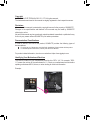
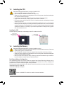
To reduce the impacts on global warming, the packaging materials of this product
are recyclable and reusable. GIGABYTE works with you to protect the environment.
For more product details, please visit GIGABYTE's website.
B550 AORUS MASTER
User's Manual
Rev. 1001
12ME-B55AMST-1001R

Copyright
© 2020 GIGA-BYTE TECHNOLOGY CO., LTD. All rights reserved.
The trademarks mentioned in this manual are legally registered to their respective owners.
Disclaimer
Information in this manual is protected by copyright laws and is the property of GIGABYTE.
Changes to the specications and features in this manual may be made by GIGABYTE
without prior notice.
No part of this manual may be reproduced, copied, translated, transmitted, or published in any
form or by any means without GIGABYTE's prior written permission.
Documentation Classications
In order to assist in the use of this product, GIGABYTE provides the following types of
documentations:
For quick set-up of the product, read the Quick Installation Guide included with the product.
For detailed product information, carefully read the User's Manual.
For product-related information, check on our website at: https://www.gigabyte.com
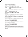
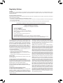
Identifying Your Motherboard Revision
The revision number on your motherboard looks like this: "REV: X.X." For example, "REV:
1.0" means the revision of the motherboard is 1.0. Check your motherboard revision before
updating motherboard BIOS, drivers, or when looking for technical information.
Example:

- 3 -
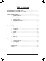
Table of Contents
B550 AORUS MASTER Motherboard Layout .................................................................4
B550 AORUS MASTER Motherboard Block Diagram ..................................................... 5
Chapter 1 Hardware Installation .....................................................................................6
1-1 Installation Precautions .................................................................................... 6
1-2 Product Specications ...................................................................................... 7
1-3 Installing the CPU .......................................................................................... 11
1-4 Installing the Memory ..................................................................................... 11
1-5 Installing an Expansion Card ......................................................................... 12
1-6 Back Panel Connectors .................................................................................. 12
1-7 Internal Connectors ........................................................................................ 15
Chapter 2 BIOS Setup ..................................................................................................24
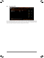
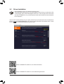
2-1 Startup Screen ............................................................................................... 24
2-2 The Main Menu .............................................................................................. 25
2-3 Favorites (F11) ............................................................................................... 26
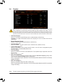
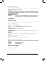
2-4 Tweaker .......................................................................................................... 27
2-5 Settings .......................................................................................................... 30
2-6 System Info. ................................................................................................... 35
2-7 Boot ................................................................................................................ 36
2-8 Save & Exit ..................................................................................................... 39
Chapter 3 Appendix ......................................................................................................40
3-1 Conguring a RAID Set .................................................................................. 40
3-2 Drivers Installation .......................................................................................... 42
3-3 Debug LED Codes ......................................................................................... 43
Regulatory Notices .................................................................................................... 47
Contact Us ................................................................................................................ 52

- 4 -
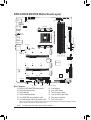
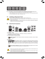
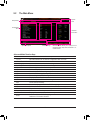
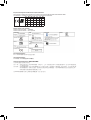
B550 AORUS MASTER Motherboard Layout
Box Contents
5B550 AORUS MASTER motherboard 5One antenna
5Motherboard driver disc 5Four SATA cables
5User's Manual 5Two thermistor cables
5Quick Installation Guide 5One noise detection cable
5One RGB LED strip extension cable 5Two Velcro cable ties
5One addressable LED strip adapter cable 5One G Connector
* The box contents above are for reference only and the actual items shall depend on the product package you obtain.
The box contents are subject to change without notice.
CPU DRAM
VGA BOOT
USB 2.0 Hub
USB20
USB_HDMI
U32G2C
U32G2_1
U32G2_2
QFLASH_PLUS
QFLED
U32G2_LAN
ATX
DB_PORT (Note)
AUDIO
DDR4_A1
DDR4_A2
DDR4_B1
DDR4_B2
ATX_12V2
ATX_12V1
AMD B550
CLR_CMOS
M_BIOS
B_BIOS
PCIEX4_1
PCIEX4_2
PCIEX16
SYS_FAN5_PUMPSYS_FAN4
SYS_FAN2
EC_TEMP1
CODEC
B550 AORUS MASTER
F_PANEL
F_USB1EC_TEMP2 SYS_FAN6_PUMP
F_USB2 SYS_FAN3
USB 2.0 Hub
D_LED2
LED_C1
LED_C2
D_LED1
F_AUDIO F_U32
SYS_FAN1
LED_CPU
M2_WIFI
CPU_OPT
iTE®
Super I/O
M2A_CPU
4280110
M2B_CPU
4280110
M2C_CPU
4280110
SATA3
420
531
BAT
Realtek®
2.5GbE LAN
TPM
Socket AM4
CPU_FAN NOISE_
SENSOR
(Note) For debug code information, please refer to Chapter 3.
THB_C

x1
- 5 -
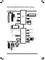
B550 AORUS MASTER Motherboard Block Diagram
AMD Socket
AM4 CPU
CPU CLK+/- (100~500 MHz)
PCI Express 4.0/3.0 Bus
PCIe 3.0 x4
LAN
RJ45
M.2 WIFI
Module
Realtek®
2.5GbE LAN
4 SATA 6Gb/s
(SATA3 0~3)
PCI Express 3.0 Bus
Center/Subwoofer
Speaker Out
Line Out
MIC
Line In
S/PDIF Out
Rear Speaker Out
CODEC
8 USB 2.0/1.1
2 USB 3.2 Gen 1
2 USB 2.0/1.1
1 USB Type-C™,
USB 3.2 Gen 2
1 USB 3.2 Gen 2
Type A
4 USB 3.2 Gen 2
Type A
AMD B550
x4x4 x1
HDMI
Switch
1 x PCI Express x4
1 x PCI Express x4
2 SATA 6Gb/s
(SATA3 4/5)
or
USB 2.0
Hub
1 M.2 Socket 3
(M2A_CPU)
LPC
Bus
TPM
iTE®
Super I/O
SPI
Bus Dual BIOS
Switch
x16
1 PCI Express x16
1 PCI Express x8
or
2 M.2 Socket 3
(M2B_CPU/
M2C_CPU)
DDR4 3200/2933/2667/2400/2133 MHz

Chapter 1 Hardware Installation
1-1 Installation Precautions
The motherboard contains numerous delicate electronic circuits and components which can become
damaged as a result of electrostatic discharge (ESD). Prior to installation, carefully read the user's
manual and follow these procedures:
•Prior to installation, make sure the chassis is suitable for the motherboard.
•Prior to installation, do not remove or break motherboard S/N (Serial Number) sticker or
warranty sticker provided by your dealer. These stickers are required for warranty validation.
•Always remove the AC power by unplugging the power cord from the power outlet before
installing or removing the motherboard or other hardware components.
•When connecting hardware components to the internal connectors on the motherboard, make
sure they are connected tightly and securely.
•When handling the motherboard, avoid touching any metal leads or connectors.
•It is best to wear an electrostatic discharge (ESD) wrist strap when handling electronic
components such as a motherboard, CPU or memory. If you do not have an ESD wrist strap,
keep your hands dry and rst touch a metal object to eliminate static electricity.
•Prior to installing the motherboard, please have it on top of an antistatic pad or within an
electrostatic shielding container.
•Before connecting or unplugging the power supply cable from the motherboard, make sure
the power supply has been turned off.
•Before turning on the power, make sure the power supply voltage has been set according to
the local voltage standard.
•Before using the product, please verify that all cables and power connectors of your hardware
components are connected.
•To prevent damage to the motherboard, do not allow screws to come in contact with the
motherboard circuit or its components.
•Make sure there are no leftover screws or metal components placed on the motherboard or
within the computer casing.
•Do not place the computer system on an uneven surface.
•Do not place the computer system in a high-temperature or wet environment.
•Turning on the computer power during the installation process can lead to damage to system
components as well as physical harm to the user.
•If you are uncertain about any installation steps or have a problem related to the use of the
product, please consult a certied computer technician.
•If you use an adapter, extension power cable, or power strip, ensure to consult with its installation
and/or grounding instructions.
- 6 -

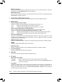
1-2 Product Specications
CPU AMD Socket AM4, support for:
3rd Generation AMD Ryzen™ processors/
New Generation AMD Ryzen™ with Radeon™ Graphics processors
(Go to GIGABYTE's website for the latest CPU support list.)
Chipset AMD B550
Memory 4 x DDR4 DIMM sockets supporting up to 128 GB (32 GB single DIMM capacity)
of system memory
Support for DDR4 3200/2933/2667/2400/2133 MHz memory modules
Dual channel memory architecture
Support for ECC Un-buffered DIMM 1Rx8/2Rx8 memory modules
Support for non-ECC Un-buffered DIMM 1Rx8/2Rx8/1Rx16 memory modules
Support for Extreme Memory Prole (XMP) memory modules
(Go to GIGABYTE's website for the latest supported memory speeds and memory
modules.)
Onboard
Graphics
Integrated in the New Generation AMD Ryzen™ with Radeon™ Graphics processors:
- 1 x HDMI port, supporting a maximum resolution of 4096x2160@60 Hz
* Support for HDMI 2.1 version, HDCP 2.3, and HDR.
Maximum shared memory of 16 GB
Audio Realtek® ALC1220-VB codec
* The back panel line out jack supports DSD audio.
Support for DTS:X® Ultra
High Denition Audio
2/4/5.1/7.1-channel
Support for S/PDIF Out
LAN Realtek® 2.5GbE LAN chip (2.5 Gbit/1 Gbit/100 Mbit)
Wireless
Communication
Module
Intel® Wi-Fi 6 AX200
- WIFI a, b, g, n, ac with wave 2 features, ax, supporting 2.4/5 GHz Dual-Band
- BLUETOOTH 5
- Support for 11ax 160MHz wireless standard and up to 2.4 Gbps data rate
* Actual data rate may vary depending on environment and equipment.
Expansion Slots 1 x PCI Express x16 slot (PCIEX16), integrated in the CPU:
- 3rd Generation AMD Ryzen™ processors support PCIe 4.0 x16 mode
- New Generation AMD Ryzen™ with Radeon™ Graphics processors support
PCIe 3.0 x16 mode
* For optimum performance, if only one PCI Express graphics card is to be installed,
be sure to install it in the PCIEX16 slot.
* The PCIEX16 slot shares bandwidth with the M2B_CPU and M2C_CPU connectors.
The PCIEX16 slot operates at up to x8 mode when a device is installed in the
M2B_CPU or M2C_CPU connector.
2 x PCI Express x16 slots (PCIEX4_1/PCIEX4_2), integrated in the Chipset:
- Supporting PCIe 3.0 x4 mode
* The PCIEX4_2 slot shares bandwidth with the SATA3 4, 5 connectors. The PCIEX4_2
slot operates at up to x2 mode when a device is installed in the SATA3 4 or SATA3 5
connector.
- 7 -

Storage Interface 1 x M.2 connector (M2A_CPU), integrated in the CPU, supporting Socket 3,
M key, type 2242/2280/22110 SSDs:
- 3rd Generation AMD Ryzen™ processors support SATA and PCIe 4.0 x4/x2
SSDs
- New Generation AMD Ryzen™ with Radeon™ Graphics processors support
SATA and PCIe 3.0 x4/x2 SSDs
2 x M.2 connectors (M2B_CPU/M2C_CPU), integrated in the CPU, supporting
Socket 3, M key, type 2242/2280/22110 SSDs:
- 3rd Generation AMD Ryzen™ processors support PCIe 4.0 x4/x2 SSDs
- New Generation AMD Ryzen™ with Radeon™ Graphics processors support
PCIe 3.0 x4/x2 SSDs
6 x SATA 6Gb/s connectors, integrated in the Chipset:
- Support for RAID 0, RAID 1, and RAID 10
USB CPU:
- 4 x USB 3.2 Gen 2 Type-A ports (red) on the back panel
Chipset:
- 1 x USB Type-C™ port on the back panel, with USB 3.2 Gen 2 support
- 1 x USB 3.2 Gen 2 Type-A port (red) on the back panel
- 2 x USB 3.2 Gen 1 ports available through the internal USB header
- 2 x USB 2.0/1.1 ports on the back panel
Chipset+2 USB 2.0 Hubs:
- 8 x USB 2.0/1.1 ports (4 ports on the back panel, 4 ports available through
the internal USB headers)
Internal
Connectors
1 x 24-pin ATX main power connector
1 x 8-pin ATX 12V power connector
1 x 4-pin ATX 12V power connector
1 x CPU fan header
1 x water cooling CPU fan header
4 x system fan headers
2 x system fan/water cooling pump headers
2 x addressable LED strip headers
2 x RGB LED strip headers
1 x CPU cooler LED strip/RGB LED strip header
3 x M.2 Socket 3 connectors
6 x SATA 6Gb/s connectors
1 x front panel header
1 x front panel audio header
1 x USB 3.2 Gen 1 header
2 x USB 2.0/1.1 headers
1 x noise detection header
1 x Trusted Platform Module (TPM) header (2x6 pin, for the GC-TPM2.0_S
module only)
1 x Thunderbolt™ add-in card connector
1 x Clear CMOS jumper
2 x temperature sensor headers
- 8 -

Back Panel
Connectors
2 x SMA antenna connectors (2T2R)
1 x HDMI port
6 x USB 2.0/1.1 ports
5 x USB 3.2 Gen 2 Type-A ports (red)
1 x USB Type-C™ port, with USB 3.2 Gen 2 support
1 x Q-Flash Plus button
1 x RJ-45 port
1 x optical S/PDIF Out connector
5 x audio jacks
I/O Controller iTE® I/O Controller Chip
Hardware
Monitor
Voltage detection
Temperature detection
Fan speed detection
Water cooling ow rate detection
Overheating warning
Fan fail warning
Fan speed control
* Whether the fan (pump) speed control function is supported will depend on the fan
(pump) you install.
Noise detection
BIOS 2 x 256 Mbit ash
Use of licensed AMI UEFI BIOS
Support for DualBIOS™
PnP 1.0a, DMI 2.7, WfM 2.0, SM BIOS 2.7, ACPI 5.0
Unique Features Support for APP Center
* Available applications in APP Center may vary by motherboard model. Supported
functions of each application may also vary depending on motherboard specications.
- @BIOS
- EasyTune
- Fast Boot
- Game Boost
- ON/OFF Charge
- RGB Fusion
- Smart Backup
- System Information Viewer
Support for Q-Flash Plus
Support for Q-Flash
Support for Xpress Install
- 9 -

Bundled
Software
Norton® Internet Security (OEM version)
XSplit Gamecaster + Broadcaster (12 months license)
Realtek® 8125 Gaming LAN Bandwidth Control Utility
Operating
System Support for Windows 10 64-bit
Form Factor ATX Form Factor; 30.5cm x 24.4cm
* GIGABYTE reserves the right to make any changes to the product specications and product-related information without
prior notice.
Please visit GIGABYTE's website
for support lists of CPU, memory
modules, SSDs, and M.2 devices.
Please visit the Support\Utility List
page on GIGABYTE's website to
download the latest version of apps.
- 10 -

Please visit GIGABYTE's website for details on hardware installation.
Dual Channel Memory Conguration
This motherboard provides four memory sockets and supports Dual Channel Technology. After the memory
is installed, the BIOS will automatically detect the specications and capacity of the memory. Enabling Dual
Channel memory mode will double the original memory bandwidth.
The four memory sockets are divided into two channels and each channel has two memory sockets as following:
Channel A: DDR4_A1, DDR4_A2
Channel B: DDR4_B1, DDR4_B2
1-3 Installing the CPU
Read the following guidelines before you begin to install the CPU:
•Make sure that the motherboard supports the CPU.
(Go to GIGABYTE's website for the latest CPU support list.)
•Always turn off the computer and unplug the power cord from the power outlet before installing the
CPU to prevent hardware damage.
•Locate the pin one of the CPU. The CPU cannot be inserted if oriented incorrectly.
•Apply an even and thin layer of thermal grease on the surface of the CPU.
•Do not turn on the computer if the CPU cooler is not installed, otherwise overheating and damage
of the CPU may occur.
•Set the CPU host frequency in accordance with the CPU specications. It is not recommended
that the system bus frequency be set beyond hardware specications since it does not meet the
standard requirements for the peripherals. If you wish to set the frequency beyond the standard
specications, please do so according to your hardware specications including the CPU, graphics
card, memory, hard drive, etc.
Installing the CPU
Locate the pin one (denoted by a small triangle) of the CPU socket and the CPU.
AM4 Socket
A Small Triangle
Marking Denotes Pin
One of the Socket AM4 CPU
A Small Triangle
Marking Denotes CPU
Pin One
1-4 Installing the Memory
Read the following guidelines before you begin to install the memory:
•Make sure that the motherboard supports the memory. It is recommended that memory of the same
capacity, brand, speed, and chips be used.
(Go to GIGABYTE's website for the latest supported memory speeds and memory modules.)
•Always turn off the computer and unplug the power cord from the power outlet before installing the
memory to prevent hardware damage.
•Memory modules have a foolproof design. A memory module can be installed in only one direction.
If you are unable to insert the memory, switch the direction.
- 11 -

Due to CPU limitations, read the following guidelines before installing the memory in Dual Channel mode.
1. Dual Channel mode cannot be enabled if only one memory module is installed.
2. When enabling Dual Channel mode with two or four memory modules, it is recommended that memory
of the same capacity, brand, speed, and chips be used.
1-5 Installing an Expansion Card
Read the following guidelines before you begin to install an expansion card:
•Make sure the motherboard supports the expansion card. Carefully read the manual that came
with your expansion card.
•Always turn off the computer and unplug the power cord from the power outlet before installing an
expansion card to prevent hardware damage.
Recommanded Dual Channel Memory Conguration:
DDR4_A1 DDR4_A2 DDR4_B1 DDR4_B2
2 Modules - - DS/SS - - DS/SS
4 Modules DS/SS DS/SS DS/SS DS/SS
(SS=Single-Sided, DS=Double-Sided, "- -"=No Memory)
1-6 Back Panel Connectors
USB 2.0/1.1 Port
The USB port supports the USB 2.0/1.1 specication. Use this port for USB devices.
SMA Antenna Connectors (2T2R)
Use this connector to connect an antenna.
HDMI Port (Note 1)
The HDMI port is HDCP 2.3 compliant and supports Dolby TrueHD and DTS HD
Master Audio formats. It also supports up to 192KHz/24bit 7.1-channel LPCM
audio output. You can use this port to connect your HDMI-supported monitor. The maximum supported
resolution is 4096x2160@60 Hz, but the actual resolutions supported are dependent on the monitor being
used.
After installing the HDMI device, make sure to set the default sound playback device to HDMI.
(The item name may differ depending on your operating system.)
Tighten the antennas to the antenna connectors and then aim the antennas correctly for better
signal reception.
•When removing the cable connected to a back panel connector, rst remove the cable from your
device and then remove it from the motherboard.
•When removing the cable, pull it straight out from the connector. Do not rock it side to side to
prevent an electrical short inside the cable connector.
- 12 -

USB 3.2 Gen 2 Port
The USB 3.2 Gen 2 port supports the USB 3.2 Gen 2 specication and is compatible to the USB 3.2 Gen 1
and USB 2.0 specication. Use this port for USB devices.
USB 3.2 Gen 2 Port (Q-Flash Plus Port)
The USB 3.2 Gen 2 port supports the USB 3.2 Gen 2 specication and is compatible to the USB 3.2 Gen 1
and USB 2.0 specication. Use this port for USB devices. Before using Q-Flash Plus (Note 2), make sure to
insert the USB ash drive into this port rst.
Q-Flash Plus Button (Note 2)
Q-Flash Plus allows you to update the BIOS when your system is off (S5 shutdown state). Save the latest
BIOS on a USB thumb drive and plug it into the Q-Flash Plus port, and then you can now ash the BIOS
automatically by simply pressing the Q-Flash Plus button. The QFLED will ash when the BIOS matching
and ashing activities start and will stop ashing when the main BIOS ashing is complete.
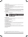
RJ-45 LAN Port
The Gigabit Ethernet LAN port provides Internet connection at up to 2.5 Gbps data rate. The following
describes the states of the LAN port LEDs.
USB Type-C™ Port
The reversible USB port supports the USB 3.2 Gen 2 specication and is compatible to the USB 3.2 Gen 1
and USB 2.0 specication. Use this port for USB devices.
Center/Subwoofer Speaker Out
Use this audio jack to connect center/subwoofer speakers.
Rear Speaker Out
Use this audio jack to connect rear speakers.
Optical S/PDIF Out Connector
This connector provides digital audio out to an external audio system that supports digital optical audio.
Before using this feature, ensure that your audio system provides an optical digital audio in connector.
Line In/Side Speaker Out
The line in jack. Use this audio jack for line in devices such as an optical drive, walkman, etc.
Line Out/Front Speaker Out
The line out jack. This jack supports audio amplifying function. For better sound quality, it is recommended
that you connect your headphone/speaker to this jack (actual effects may vary by the device being used).
Mic In/Side Speaker Out
The Mic in jack.
(Note 1) For new Generation AMD Ryzen™ with Radeon™ Graphics processors only.
(Note 2) To enable the Q-Flash Plus function please visit the "Unique Features" webpage of GIGABYTE's
website.
Connection/
Speed LED Activity LED
LAN Port
Connection/Speed LED:
State Description
Orange 2.5 Gbps data rate
Green 1 Gbps data rate
Off 100 Mbps data rate
Activity LED:
State Description
Blinking Data transmission or receiving is occurring
Off No data transmission or receiving is occurring
- 13 -

Please visit GIGABYTE's website for details on conguring the audio software.
If you want to install a Side Speaker, you need to retask either the Line in or Mic in jack to be
Side Speaker out through the audio driver.
Audio Jack Congurations:
Jack Headphone/
2-channel 4-channel 5.1-channel 7.1-channel
Center/Subwoofer Speaker
Out a a
Rear Speaker Out a a a
Line In/Side Speaker Out a
Line Out/Front Speaker Out a a a a
Mic In/Side Speaker Out a
- 14 -

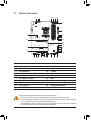
1-7 Internal Connectors
Read the following guidelines before connecting external devices:
•First make sure your devices are compliant with the connectors you wish to connect.
•Before installing the devices, be sure to turn off the devices and your computer. Unplug the power
cord from the power outlet to prevent damage to the devices.
•After installing the device and before turning on the computer, make sure the device cable has
been securely attached to the connector on the motherboard.
1) ATX_12V1/ATX_12V2
2) ATX
3) CPU_FAN
4) SYS_FAN1/2/3/4
5) SYS_FAN5_PUMP/SYS_FAN6_PUMP
6) CPU_OPT
7) EC_TEMP1/EC_TEMP2
8) D_LED1/D_LED2
9) LED_CPU
10) LED_C1/LED_C2
11) NOISE_SENSOR
12) SATA3 0/1/2/3/4/5
13) M2A_CPU/M2B_CPU/M2C_CPU
14) F_PANEL
15) F_ AUDIO
16) F_U32
17) F_USB1/F_USB2
18) TPM
19) CLR_CMOS
20) BAT
21) CPU/DRAM/VGA/BOOT
22) THB_C
1454
21
20
2
11
7
12
5
4
17 1816815
1 1
4
710
19
13
13
9
13
3 8 106
- 15 -
22

DEBUG
PORT
G.QBOFM
131
2412
ATX
1/2) ATX_12V1/ATX_12V2/ATX (2x2, 2x4, 12V Power Connectors and 2x12 Main Power
Connector)
With the use of the power connector, the power supply can supply enough stable power to all the components
on the motherboard. Before connecting the power connector, rst make sure the power supply is turned
off and all devices are properly installed. The power connector possesses a foolproof design. Connect the
power supply cable to the power connector in the correct orientation.
The 12V power connector mainly supplies power to the CPU. If the 12V power connector is not connected,
the computer will not start.
To meet expansion requirements, it is recommended that a power supply that can withstand high
power consumption be used (500W or greater). If a power supply is used that does not provide the
required power, the result can lead to an unstable or unbootable system.
ATX:
Pin No. Denition Pin No. Denition
1 3.3V 13 3.3V
2 3.3V 14 -12V
3 GND 15 GND
4 +5V 16 PS_ON (soft On/Off)
5 GND 17 GND
6 +5V 18 GND
7 GND 19 GND
8 Power Good 20 NC
9 5VSB (stand by +5V) 21 +5V
10 +12V 22 +5V
11 +12V (Only for 2x12-pin
ATX)
23 +5V (Only for 2x12-pin ATX)
12 3.3V (Only for 2x12-pin ATX) 24 GND (Only for 2x12-pin ATX)
ATX_12V2:
Pin No. Denition Pin No. Denition
1 GND (Only for 2x4-pin 12V) 5 +12V (Only for 2x4-pin 12V)
2 GND (Only for 2x4-pin 12V) 6 +12V (Only for 2x4-pin 12V)
3 GND 7 +12V
4 GND 8 +12V
DEBUG
PORT
G.QBOFM
ATX_12V2
41
85
ATX_12V1:
Pin No. Denition
1 GND
2 GND
3 +12V
4 +12V
ATX_12V1
1
3
2
4
- 16 -

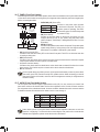
5) SYS_FAN5_PUMP/SYS_FAN6_PUMP (System Fan/Water Cooling Pump Headers)
The fan/pump headers are 4-pin. Most fan headers possess a foolproof insertion design. When connecting
a fan cable, be sure to connect it in the correct orientation (the black connector wire is the ground wire). The
speed control function requires the use of a fan with fan speed control design. For optimum heat dissipation,
it is recommended that a system fan be installed inside the chassis. The header also provides speed control
for a water cooling pump, refer to Chapter 2, "BIOS Setup," "Settings\Smart Fan 5," for more information.
6) CPU_OPT (Water Cooling CPU Fan Header)
The fan header is 4-pin and possesses a foolproof insertion design. Most fan headers possess a foolproof
insertion design. When connecting a fan cable, be sure to connect it in the correct orientation (the black
connector wire is the ground wire). The speed control function requires the use of a fan with fan speed control
design.
DEBUG
PORT
G.QBOFM
1
Pin No. Denition
1 GND
2 Voltage Speed Control
3 Sense
4 PWM Speed Control
Pin No. Denition
1 GND
2 Voltage Speed Control
3 Sense
4 PWM Speed Control
3/4) CPU_FAN/SYS_FAN1/2/3/4 (Fan Headers)
All fan headers on this motherboard are 4-pin. Most fan headers possess a foolproof insertion design.
When connecting a fan cable, be sure to connect it in the correct orientation (the black connector wire is
the ground wire). The speed control function requires the use of a fan with fan speed control design. For
optimum heat dissipation, it is recommended that a system fan be installed inside the chassis.
•Be sure to connect fan cables to the fan headers to prevent your CPU and system from
overheating. Overheating may result in damage to the CPU or the system may hang.
•These fan headers are not conguration jumper blocks. Do not place a jumper cap on the headers.
CPU_FAN SYS_FAN3SYS_FAN1/SYS_FAN2/
SYS_FAN4
DEBUG
PORT
G.QBOFM
1
DEBUG
PORT
G.QBOFM
1
SYS_FAN6_PUMP
DEBUG
PORT
G.QBOFM
1
DEBUG
PORT
G.QBOFM
1
SYS_FAN5_PUMP
DEBUG
PORT
G.QBOFM
1
Pin No. Denition
1 GND
2 Voltage Speed Control
3 Sense
4 PWM Speed Control
- 17 -

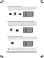
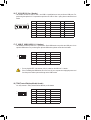
8) D_LED1/D_LED2 (Addressable LED Strip Headers)
The headers can be used to connect a standard 5050 addressable LED strip, with maximum power rating
of 5A (5V) and maximum number of 1000 LEDs.
Pin No. Denition
1 V (5V)
2 Data
3 No Pin
4 GND
Connect one end of the included addressable LED strip adapter cable
to this header and the other end to your addressable LED strip. The
power pin (marked with a triangle on the plug) of the LED strip must
be connected to Pin 1 of the addressable LED strip header. Incorrect
connection may lead to the damage of the LED strip.
7) EC_TEMP1/EC_TEMP2 (Temperature Sensor Headers)
Connect the thermistor cables to the headers for temperature detection.
Pin No. Denition
1 SENSOR IN
2 GND
1
1
EC_TEMP1
EC_TEMP2
Before installing the devices, be sure to turn off the devices and your computer. Unplug the power
cord from the power outlet to prevent damage to the devices.
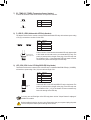
9) LED_CPU (CPU Cooler LED Strip/RGB LED Strip Header)
The header can be used to connect a CPU cooler LED strip or a standard 5050 RGB LED strip (12V/G/R/B),
with maximum power rating of 2A (12V) and maximum length of 2m.
Pin No. Denition
1 12V
2 G
3 R
4 B
Connect the CPU cooler LED strip/RGB LED strip to the header. The
power pin (marked with a triangle on the plug) of the LED strip must
be connected to Pin 1 (12V) of this header. Incorrect connection may
lead to the damage of the LED strip.
For how to turn on/off the lights of the LED strip please visit the "Unique Features" webpage of
GIGABYTE's website.
RGB LED
Strip
1
12V
1
DEBUG
PORT
G.QBOFM
1 1
F_USB30 F_U
B_
F_ F_
_
B
BS_
B
SB_
B
_S
S_
_
B
_U
_
B
S
123
123
123
123
1
1
1
1
BSS
S
_S
SSU
1 2 3 4 5
S3 BSSS
U
__ 3
F_USB3F
S _
S _
S _
SF
B_
B_
F
_0
S
S
_0F
_F
_
_
__B
U
S _S
_ SF_
B
USB0_B
B_
B_
F_USB3
F_USB303
_
_3U
S_
F_USB30 F_U
B_
F_ F_
_
B
BS_
B
SB_
B
_S
S_
_
B
_U
_
B
S
123
123
123
123
1
1
1
1
BSS
S
_S
SSU
1 2 3 4 5
S3 BSSS
U
__ 3
F_USB3F
S _
S _
S _
SF
B_
B_
F
_0
S
S
_0F
_F
_
_
__B
U
S _S
_ SF_
B
USB0_B
B_
B_
F_USB3
F_USB303
_
_3U
S_
D_LED1 D_LED2
Addressable LED
Strip Adapter Cable
1
- 18 -

Before installing the devices, be sure to turn off the devices and your computer. Unplug the power
cord from the power outlet to prevent damage to the devices.
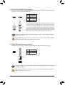
10) LED_C1/LED_C2 (RGB LED Strip Headers)
The headers can be used to connect a standard 5050 RGB LED strip (12V/G/R/B), with maximum power
rating of 2A (12V) and maximum length of 2m.
Pin No. Denition
1 12V
2 G
3 R
4 B
1
Connect one end of the RGB LED strip extension cable to the header
and the other end to your RGB LED strip. The black wire (marked with
a triangle on the plug) of the extension cable must be connected to
Pin 1 (12V) of this header. The 12V pin (marked with an arrow) on the
other end of the extension cable must be lined up with the 12V of the
LED strip. Be careful with the connection orientation of the LED strip;
incorrect connection may lead to the damage of the LED strip.
For how to turn on/off the lights of the LED strip please visit the "Unique Features" webpage of
GIGABYTE's website.
LED_C2
1
LED_C1
DEBUG
PORT
G.QBOFM
DEBUG
PORT
G.QBOFM
12VRGB
BG12VR
12V
1
RGB LED
Strip
12VRGB
BG12VR
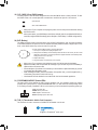
11) NOISE_SENSOR (Noise Detection Header)
This header can be used to connect a noise detection cable to detect the noise inside the case.
Pin No. Denition
1 Noise Detection
2 GND
Before connecting the cable to the header, make sure to remove the jumper cap; re-place the
jumper cap if the header is not in use.
For more information on the noise detection function, please visit the "Unique Features" webpage
of GIGABYTE's website.
1
Noise Detection
Cable
1
- 19 -

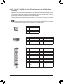
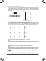
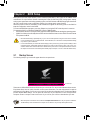
13) M2A_CPU/M2B_CPU/M2C_CPU (M.2 Socket 3 Connectors)
The M.2 connectors support M.2 SATA SSDs or M.2 PCIe SSDs and support RAID conguration. Please
note that an M.2 PCIe SSD cannot be used to create a RAID set either with an M.2 SATA SSD or a SATA
hard drive. Refer to Chapter 3, "Conguring a RAID Set," for instructions on conguring a RAID array.
Follow the steps below to correctly install an M.2 SSD in the M.2 connector.
Step 1:
Locate the M.2 connector where you will install the M.2 SSD, use a screwdriver to unfasten the screw on
the heatsink and then remove the heatsink. Remove the protective lm from the thermal pad on the M.2
connector.
Step 2:
Locate the proper mounting hole based on the length of your M.2 SSD drive. If needed, move the standoff
to the desired mounting hole. Insert the M.2 SSD into the M.2 connector at an angle.
Step 3:
Press the M.2 SSD down and then secure it with the screw. Replace the heatsink and secure it to the original
hole. Make sure to remove the protective lm from the bottom of the heatsink before replacing the heatsink.
Select the proper hole for the M.2 SSD to be installed and refasten the screw and standoff.
12) SATA3 0/1/2/3/4/5 (SATA 6Gb/s Connectors)
The SATA connectors conform to SATA 6Gb/s standard and are compatible with SATA 3Gb/s and SATA
1.5Gb/s standard. Each SATA connector supports a single SATA device. The SATA connectors support
RAID 0, RAID 1, and RAID 10. Refer to Chapter 3, "Conguring a RAID Set," for instructions on conguring
a RAID array.
Pin No. Denition
1 GND
2 TXP
3 TXN
4 GND
5 RXN
6 RXP
7 GND
1
1
SATA3 4 2 0
5 3 1
7
7
DEBUG
PORT
G.QBOFM
DEBUG
PORT
G.QBOFM
DEBUG
PORT
G.QBOFM
F_USB30 F_U
B_
F_ F_
_
B
BS_
B
SB_
B
_S
S_
_
B
_U
_
B
S
123
123
123
123
1
1
1
1
BSS
S
_S
SSU
1 2 3 4 5
S3 BSSS
U
__ 3
F_USB3F
S _
S _
S _
SF
B_
B_
F
_0
S
S
_0F
_F
_
_
__B
U
S _S
_ SF_
B
USB0_B
B_
B_
F_USB3
F_USB303
_
_3U
S_
80110 60 42
M2A_CPU
F_USB30 F_U
B_
F_ F_
_
B
BS_
B
SB_
B
_S
S_
_
B
_U
_
B
S
123
123
123
123
1
1
1
1
BSS
S
_S
SSU
1 2 3 4 5
S3 BSSS
U
__ 3
F_USB3F
S _
S _
S _
SF
B_
B_
F
_0
S
S
_0F
_F
_
_
__B
U
S _S
_ SF_
B
USB0_B
B_
B_
F_USB3
F_USB303
_
_3U
S_
80110 60 42
M2B_CPU (Note)
F_USB30 F_U
B_
F_ F_
_
B
BS_
B
SB_
B
_S
S_
_
B
_U
_
B
S
123
123
123
123
1
1
1
1
BSS
S
_S
SSU
1 2 3 4 5
S3 BSSS
U
__ 3
F_USB3F
S _
S _
S _
SF
B_
B_
F
_0
S
S
_0F
_F
_
_
__B
U
S _S
_ SF_
B
USB0_B
B_
B_
F_USB3
F_USB303
_
_3U
S_
80110 60 42
M2C_CPU (Note)
(Note) The PCIEX16 slot shares bandwidth with the M2B_CPU and M2C_CPU connectors. The PCIEX16
slot operates at up to x8 mode when a device is installed in the M2B_CPU or M2C_CPU connector.
- 20 -
La pagina si sta caricando...
La pagina si sta caricando...
La pagina si sta caricando...
La pagina si sta caricando...
La pagina si sta caricando...
La pagina si sta caricando...
La pagina si sta caricando...
La pagina si sta caricando...
La pagina si sta caricando...
La pagina si sta caricando...
La pagina si sta caricando...
La pagina si sta caricando...
La pagina si sta caricando...
La pagina si sta caricando...
La pagina si sta caricando...
La pagina si sta caricando...
La pagina si sta caricando...
La pagina si sta caricando...
La pagina si sta caricando...
La pagina si sta caricando...
La pagina si sta caricando...
La pagina si sta caricando...
La pagina si sta caricando...
La pagina si sta caricando...
La pagina si sta caricando...
La pagina si sta caricando...
La pagina si sta caricando...
La pagina si sta caricando...
La pagina si sta caricando...
La pagina si sta caricando...
La pagina si sta caricando...
La pagina si sta caricando...
-
 1
1
-
 2
2
-
 3
3
-
 4
4
-
 5
5
-
 6
6
-
 7
7
-
 8
8
-
 9
9
-
 10
10
-
 11
11
-
 12
12
-
 13
13
-
 14
14
-
 15
15
-
 16
16
-
 17
17
-
 18
18
-
 19
19
-
 20
20
-
 21
21
-
 22
22
-
 23
23
-
 24
24
-
 25
25
-
 26
26
-
 27
27
-
 28
28
-
 29
29
-
 30
30
-
 31
31
-
 32
32
-
 33
33
-
 34
34
-
 35
35
-
 36
36
-
 37
37
-
 38
38
-
 39
39
-
 40
40
-
 41
41
-
 42
42
-
 43
43
-
 44
44
-
 45
45
-
 46
46
-
 47
47
-
 48
48
-
 49
49
-
 50
50
-
 51
51
-
 52
52


Gigabyte B550 AORUS MASTER Manuale del proprietario
- Categoria
- Schede madri
- Tipo
- Manuale del proprietario
in altre lingue
Documenti correlati
-
Gigabyte B550 AORUS ELITE Manuale del proprietario
-
GIGA-BYTE TECHNOLOGY B550M AORUS PRO Manuale utente
-
Gigabyte B550M S2H Manuale utente
-
-
-
-
-
-
Gigabyte X570 AORUS ULTRA Manuale del proprietario
-