Pottinger EUROTOP 650 MULTITAST Istruzioni per l'uso
- Categoria
- Mini motozappe
- Tipo
- Istruzioni per l'uso
Questo manuale è adatto anche per

Operator‘s manual
GB
+ INSTRUCTIONS FOR PRODUCT DELIVERY . . . Page 3
"Translation of the original Operating Manual" Nr. 99 272.GB.80K.0
• Double Rotary Swather
TOP 650 multitast
(Type SK 272 : + . . 01001)
EUROTOP 650 multitast
(Type SK 272 : + . . 01201)
EUROTOP 651 A
(Type SK 272 : + . . 01486)

ALLG./BA SEITE 2 / 0000-GB
Important information concerning Product
Liability.
According to the laws governing product liability, the manufacturer and dealer are obliged to hand the
operating manual to the customer at the time of sale, and to instruct them in the recommended operating,
safety, and maintenance regulations. Confirmation is necessary to prove that the machine and operating
manual have been handed over accordingly.
For this purpose,
- document A is to be signed and sent to Pöttinger,
- document B remains with the dealer supplying the machine,
- and the customer receives document C.
In accordance with the laws of product liability, every farmer is an entrepreneur.
According to the laws of product liability, property damage is damage caused by a machine and not to
it. An excess of Euro 500 is provided for such a liabilioty.
In accordance with the laws of product liability, entrepreneurial property damages are excluded from
the liability.
Attention! Should the customer resell the machine at a later date, the operating manual must be given
to the new owner who must then be instructed in the recommended regulations referred to herein.
GB Dear Farmer
You have just made an excellent choice. Naturally we are very happy
and wish to congratulate you for having chosen Pöttinger. As your
agricultural partner, we offer you quality and efficiency combined with
reliable servicing.
In order to assess the spare-parts demand for our agricultural machines
and to take these demands into consideration when developing new
machines, we would ask you to provide us with some details.
Furthermore, we will also be able to inform you of new developments.
Pöttinger Newsletter
www.poettinger.at/landtechnik/index_news.htm
The latest expert information, useful links and entertainment

Dokument D
GB-0600 Dokum D Anbaugeräte
PÖTTINGER Landtechnik GmbH
Industriegelände 1
A-4710 Grieskirchen
Tel. 07248 / 600 -0
Telefax 07248 / 600-2511
T Machine checked according to delivery note. All attached parts removed. All safety equipment, drive shaft and operating
devices at hand.
T Operation and maintenance of machine and/or implement according to operating instructions explained to the customer.
T Tyres checked re. correct pressure.
T Wheel nuts checked re. tightness.
T Drive shaft cut to correct lenght.
T *VYYLJ[WV^LY[HRLVɈZWLLKPUKPJH[LK
T Fitting to tractor carried out: to three-point linkage
T Trial run carried out and no defects found.
T Functions explained during trial run.
T Pivoting in transporting and operating position explained.
T Information given re. optional extras.
T Absolute need to read the operating manual indicated.
Please check. X
According to the product liability please check the above mentioned items.
INSTRUCTIONS FOR
PRODUCT DELIVERY
GB
In order to prove that the machine and the operating manual have been properly delivered, a confirmation is necessary.
For this purpose please do the following:
- sign the document A and send it to the company Pöttinger or via the internet to www.poettinger.at
- document B stays with the specialist factory delivering the machine.
- document C stays with the customer.

GB
TABLE OF CONTENTS
1100_GB-INHALT_272 - 4 -
Observe Safety Hints in the supplement!
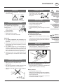
CE sign
The CE sign, which is affixed by the manufacturer, indicates outwardly that this machine conforms to
the engineering guideline regulations and the other relevant EU guidelines.
EU Declaration of ConformityBy signing the EU Declaration of Conformity, the manufacturer declares that
the machine being brought into service complies with all relevant safety and health requirements.
Meaning of warning signs
Do not enter rotor area while driving motor
is running.
Never reach into the crushing danger area as
long as parts may move.
Stay clear of swinging area of implements
495.173
Table of contents
Meaning of warning signs ................................................................. 4
CE sign .............................................................................................. 4
Hitching ............................................................................................. 5
Hydraulic connection......................................................................... 5
Lenght of the drive shaft .................................................................. 6
Lowering the machine ....................................................................... 7
Conversion from working to transport position ................................. 8
Driving on public roads ..................................................................... 9
Working position .............................................................................. 10
Conversion from transport to working position ............................... 10
Preparing for operation ................................................................... 11
Setting the feeler wheel ................................................................... 11
Adjusting the rotor lifting speed ...................................................... 12
THE SYSTEM "MULTITAST"
Swather with „MULTITAST“ system ............................................... 13
EUROTOP 650 multitast .................................................................. 13
EUROTOP 651 multitast / EUROTOP 801 multitast........................ 14
Swather without „MULTITAST“ system (special design
EUROTOP 650 / 800... - Bj. 1999) ................................................... 14
OPERATION
General guidelines for working with the machine ........................... 15
Safety hints ...................................................................................... 15
P.t.o. speed ...................................................................................... 15
Turning manœuvre in working position .......................................... 15
WORKING ON SLOPES
Take care when turning on slopes! .................................................. 16
MAINTENANCE
Safety point ..................................................................................... 17
General maintenance hints .............................................................. 17
Cleaning of machine parts .............................................................. 17
Parking in the ope ........................................................................... 17
Winter storage ................................................................................. 17
Drive shafts ...................................................................................... 17
Hydraulic unit .................................................................................. 17
Tine arms ......................................................................................... 18
Spring tines ..................................................................................... 18
Lubrication chart ............................................................................ 20
Technical data ................................................................................. 21
Defined use of the Rotary Swather ................................................. 21
Optional extra: ................................................................................. 21
Position of Vehicle Identification Plate ............................................ 21
SUPPLEMENT
Recommendations for work safety ................................................ 24
Driveshaft ........................................................................................ 25
Lubricants ........................................................................................ 27
Combination of tractor and mounted implement ............................ 29

GBHITCHING
- 5 -
0600-GB-ANBAU_272
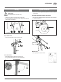
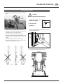
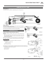
Hydraulic connection
There must be one single action hydraulic connection available
on the tractor.
Connecting hydraulic system to the tractor
- Only connect hydraulic system to the tractor when stopcock
is closed (position A).
Release rope
- Run rope (S) into tractor cabin.
A
E
TD44/94/8
ST
TD 78-98-02
Hitching
Safety hints:
see supplement-A1 points 8a. - 8h.)
- Hitching the machine to the lifting gear of the tractor.
- Fix the hydraulic lower link (U) in such a way that the machine
cannot swing out sideways.
up to 2003 model
- Raise jackstand (5b) and secure with bolt (B).
from 2004 model
- Pull jackstand (5a) to release and swing up (5b)
- Spring loaded bolt (B) locks into place automatically.
B
044-01-008
5a
5b

GBHITCHING
- 6 -
0600-GB-ANBAU_272
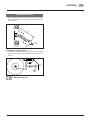
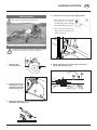
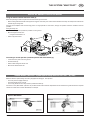
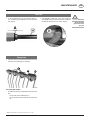
Lenght of the drive shaft
- Before using for the first time, the length of the drive shaft must be
checked and adjusted if necessary (see also supplement B „Drive
shaft adaption“).
Procedure for cutting to length
- To determine length required, set implement in closest working
position (L2) to tractor, hold driveshaft halves side by side and
mark off.
025-05-04
L2
104-03-02
EW
GW
WW
EL
WW= Wide-angle joint

GBHITCHING
- 7 -
0600-GB-ANBAU_272
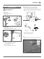
Should problems occur when disconnecting:
- Move servo-valve (ST) briefly to „lower“ position (s).
Doing this will reduce any possible pressure remaining in the
connector and allows a trouble-free disconnection of the hydraulic
lines.
- Remove pull rope from tractor cabin.
- Disconnect appliance from tractor.
Note:
Storing height or width can be decreased by removing tine arms
(1a).
Lowering the machine
The machine can be lowered both from the working position
and from the transport position.
Park machine stabily!
up to 2003 model
- Swing support stand down(5a)
- Locking pin (B)
from 2004 model
- Disengage spring loaded bolt (B)
- Swing jackstand (5a) down and lock into place
- Pull off drive shaft (GW) and rest on support.
Do not use retaining chain for this.
- Close stop cock (Pos. A)
- Disconnect hydraulic lines (EW) from tractor.
B
044-01-008
5a
5b
A
E
TD 26/92/16
s
h
0
ST
TD 28/99/14
EW
EL

GB
TRANSPORT POSITION
0600_GB-TRANSPORT_272 - 8 -
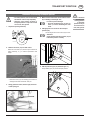
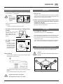
• For safety reasons, turn off drive shaft
and wait for rotor to stop completely.
• Changing from working position to
transport position is only to be carried
out on even, firm ground.
1. Stopcock opened (position E).
2. Remove tine arms (1a) from both rotors.
Removal of tine arms (1a) should only be carried out
when necessary, e. g. to reduce implement's total
height.
• Place tine arms (1a) onto holding pins located on
carriage frame and secure with linch pin.
3. Swing guard rail inward, left and right, and secu-
re with spring pin.
4. Make sure that swivel area is free and that nobo-
dy is standing in the danger area.
In order to prevent damage:
- bring the protection pipe (10) into po-
sition „A“ before swivelling the rotor
units.
5. Swinging both rotor units into the transport
position (H2).
• Use the single action servo-valve (ST) for this.
Attention!
Check whether the locking hooks (10) are
locked into position correctly.
6. Swivel protection pipe (10) backward (pos. T).
The protection pipe (10) in the transport position.
A
E
TD44/94/8
ST
A
T
TD 78-98-04
10
6a
Conversion from working to transport position
10
TD 78-98-03
Attention!
Changing from
working position
to transport
position is only to
be carried out on
even, firm ground.

GB
TRANSPORT POSITION
0600_GB-TRANSPORT_272 - 9 -
Attention!
Observe the following steps:
• Swivel the rotary units
completely up (H2)
• Close stop cock
(position A)
Locking occurs hydraulically, the locking hooks (10) are
there for additional safety.
If this is not observed then under certain circumstances
the transport width can be greater than 3m.
Only transport the machine in the transport position
(H2)!
10
TD 78-98-03
Driving on public roads
021-06-01
< 3 m
A
E
TD44/94/8
• Observe the official regulations of your country.
• Travelling on open roads may only be carried out as
described in chapter „Transport position“.
• Protection devices must be in proper condition.
• Before travelling bring all swivelling parts into their correct
positions and secure against dangerous changes to
position.
• Check that lighting functions before travelling.
• Important information can also be found in the
supplement of this operating manual.

- 10 -
0600_GB-ARBEITSSTELLUNG_272
GBWORKING POSITION
4. Lower both rotor units into operating position.
• Move single action servo-valve
(ST) briefly to "lift" position
simultaneously pulling on rope (S).
This releases locking hooks (10).
• Then move servo-valve (ST) to
"lower" position and lower rotor
units to the ground.
5. Swing guard rails (6), left and right, outward and
secure with spring pin (6a).
Working position
Stand clear of implement's swivel range.
Conversion from transport to working position
Changing from working position to transport position
is only to be carried out on even, firm ground.
1. Stopcock ope-
ned (position E).
2. Swing guard rail (10)
inward (pos. A), left
and right, and secure
with spring pin (6a).
3. Make sure that swivel area is free and that nobody is
standing in the danger area.
A
E
TD44/94/8
ST
A
T
TD 78-98-04
10
6a
10
TD 78-98-03a

- 11 -
0600_GB-ARBEITSSTELLUNG_272
GBWORKING POSITION
Preparing for operation
Caution!
Do not enter rotor area while
driving motor is running.
1. Install all tine arms onto both rotors.
• Place tine bearers onto rotor arms and secure with linch pin.
85 cm (12x)
91 cm (10x)
2. Swing guard rails (6), left and right, outward and
secure with spring pin (6a).
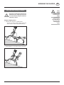
3. Pull trap sheet out and secure with T-screw.
Normal adjustment is a gap of about 40 cm from tines.
Setting the feeler wheel
• Select the smallest possible gap between feeler wheel and tines
(A) and tidy raking will resultat.
- insert the bolt in the relevant position according to feeder
mass
- then tighten the bearing bar, free of play, with the hexagonal
screw (SK).
TD 44/94/11
6
6a
z 40 cm
A
SK
TD 62/97/1

- 12 -
0600_GB-ARBEITSSTELLUNG_272
GBWORKING POSITION
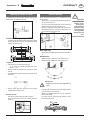
Adjusting the rotor lifting speed
" I]Z gdidg a^[i^c\ heZZY XVc WZ VY_jhiZY jh^c\ i]Z ]VcY l]ZZa
9
" I]Zgdidga^[ia^b^iXVcWZVY_jhiZYjh^c\i]ZgdY=
D
H
021-06-03

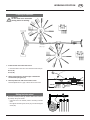
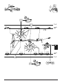
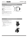
Swather with „MULTITAST“ system
Turning joint (1)
The rotary units are not seated on rigid bearings, but in a turning joint (1).
Feeler wheel (2)
Using the feeler wheel enables the tines to attain optimum ground adaption
(6°) even on extremely uneven surfaces.
As the tines are located quite close to the feeler wheel they are able to follow
the uneven ground optimumly. The result is very tidy raking.
EUROTOP 650 multitast
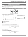
Using the machine without the feeler wheel (2)
Particular operating conditions require that the feeler wheel (2) be
removed.
• When working without the feeler wheel (2) the turning joint of the rotary
unit must be fixed. Otherwise the rotary unit will tip down and the tines
will then dig into the ground.
However ground adaption with a fixed turning joint is no longer optimal. For
this reason, this type of operation should be avoided as often as possible.
Fixing the rotary unit:
• Aline both rotary units as parallel as possible on even ground.
• Mount plate „3“
- hexagonal screws M12 x 30
- washers 13 / 30 x 5
• Remove (2) feeler wheel
Converting to normal operation (machine operation with feeler wheel (2)):
• Lower both rotary units onto even ground
• Fit feeler wheel (2)
• Remove plate „3“
GB
THE SYSTEM "MULTITAST"
- 13 -
0000-GB MULTITAST (272)

GBTHE SYSTEM "MULTITAST"
- 14 -
0000-GB MULTITAST (272)
TD 159-99-1 b
3a 3b
M16 x 70
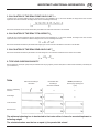
EUROTOP 651 multitast / EUROTOP 801 multitast
Using the machine without the feeler wheel (2)
Particular operating conditions require that the feeler wheel (2) be removed.
• When working without the feeler wheel (2) the turning joint of the rotary unit must be fixed. Otherwise the rotary unit will tip down and the tines
will then dig into the ground.
However ground adaption with a fixed turning joint is no longer optimal. For this reason, this type of operation should be avoided as often as
possible.
Fixing the rotary unit:
• Aline both rotary units as parallel as possible on even ground.
• Mount hexagonal screws "3a"
- hexagonal screws M12 x 70
• Remove (2) feeler wheel
Converting to normal operation (machine operation with feeler wheel (2)):
• Lower both rotary units onto even ground
• Fit feeler wheel (2)
• Remove both hexagonal screws "3a"
• Mount both rubber buffers "3b"
Swather without „MULTITAST“ system (special design EUROTOP 650 / 800... - Bj. 1999)
Machines with this special design are factory-equipped accordingly for this operation.
- The rotary units are rigidly seated (1)
- The feeler wheels (2) do not exist
- The running wheels on the rotary units are positioned forward (4)
Conversion to the „MULTITAST“ system is not provided for with these machines. Expenditure for this would be too great because the complete
central unit of both rotors must be dismantled, for example.
System "MULTITAST"

GB
272 / EINSATZ 9900-GB - 15 -
OPERATION
General guidelines for working with the machine
- All work in the immediate area of the rotors may only be carried
out when the p.t.o. is switched off.
Caution!
Do not enter
rotor area while
driving motor is
running.
• Choose the speed of travel so that all crops are picked up
thoroughly.
- In cases of overloading, shift down one gear.
• Put tractor control device (ST) into "floating position
or lower".
The plungers of both lifting
cylinders can than move
freely enabling the rotor
units to adapt to the uneven
ground.
• Set height of lifting
gear (H1)
- In order to obtain
tidy raking operation,
the rotor must be as
horizontal as possible.
A very slight inclination
forward is allowed.
Crank handle (8)
- The tine height is adjusted using the crank handle (8). Tines
should lightly touch the ground.
An adjustment that is to deep will dirty the forage or damage
the turf.
- Check adjustment regularly during work operation.
Important points befor starting work
(see supplement-A1 points 1, 2, 3 and 4)
Safety hints
1. Turn p.t.o. on.
Turn the p.t.o. on only when all safety devices (coverings, protective
aprons, casings, etc.) are in proper condition and attached to the
implement in the correct protective positions.
2. Switch-on the machine only in working position and do
not exceed the prescribed power take-off speed (for
example max. 540 rpm).
A transfer, which is located near the gear, advises which p.t.o.
speed your machine is equipped for.
P.t.o. speed
- P.t.o. speed max. = 540 rpm
The most favourable p.t.o. rpm is about 450 rpm.
- Should the forage be pulled back from the swath into the raked
strips (untidy operation), then the p.t.o. rpm is to be reduced.
- The curved track for tine arm control can be adjusted (optimum
use of the tine control).
- Tractor's lower link (U) must be set so that there is no sideways
play in order to prevent tedder from swinging back and forth.
Turning manœuvre in working position
The rotors can be swung up (pos. H1) using the single action
servo-valve (ST). The drive must not be turned off for this.
Caution!
Do not enter rotor area while driving motor is
running.
495.173
A
E
TD 26/92/16
s
h
0
ST
TD 50/96/17
H1
TD 27/99/11
H1

- 16 -
9700-GB HANGFAHRT_288
GB
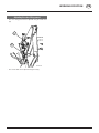
Take care when turning on slopes!
The tractor's travelling characteristics are
influenced by the weight (G) of the rotor
unit. This can lead to dangerous situations,
especially on slopes.
Danger of tipping occurs
• when the rotor units are in a raised position
- The rotor unit facing uphill is always raised first
which results in uneven weight distribution (G).
• when travelling in a curve with the rotor units raised
TD 33/97/1
G
TD 33/97/2
Safety
advice
• Reduce speed
in curves accor-
dingly.
• It is better to
travel in reverse
on a slope than to
carry out a risky
turning mano-
euvre.
WORKING ON SLOPES

- 17 -
GB
0400_GB-BA-Allg. Wartung
Parking in the ope
When parking in the open for
long periods of time, clean
piston rods and then coat
with grease.
FETT
TD 49/93/2
Safety
points!
• Turn engine off
when adjustment,
service and repair
work is to be
done.
• Do not work un-
der the machine
without safe
support.
• Retighten all
screws after the
first hours of
operation..
Cleaning of machine parts
Attention! Do not use high-pressure washers for the
cleaning of bearing- and hydraulic parts.
- Danger of rust!
- After cleaning, grease the machine according to the
lubrication chart and carry out a short test run.
- Cleaning with too high pressure may do damage to
varnish.
Safety point
• Turn engine off when adjustment, service and repair
work is to be done.
Hydraulic unit
Caution! Danger of injury or infection!
Under high pressure, escaping fluids can penetrate
the skin. Therefore seek immediate medical help!
After the first 10 operating hours and then every
consecutive 50 operating hours
- Check the hydraulic unit and lines for tightness and
retighten screw connections if necessary.
Before operation
- Check hydraulic hoses for wear.
Replace worn or damaged hydraulic hoses immediately.
The replacement hoses must meet the manufacturer’s
technical requirements.
Hose lines are subject to natural ageing. The period of
use should not exceed 5 – 6 years.
Winter storage
- Thoroughly clean machine before storage.
- Put up protection against weather.
- Change or replenish gear oil.
- Protect exposed parts from rust.
- Lubricate all greasing points according to lubrication
chart.
Drive shafts
- see notes in the supplement
For maintenance please note!
The instructions in this operating manual are always
valid.
In case there are no special instructions available, then
the notes in the accompanying drive shaft manufacturer´
instructions are valid.
Repair In-
structions
Please refer to
repair instructions
in supplement (if
available)
MAINTENANCE
General maintenance hints
In order to keep the implement in
good condition after long periods
of operation, please observe the
following points:
- Tighten all screws after the first
hours of operation.
In particular check:
- blade screws on the mowers
- tine screws on the swather and tedder.
Spare part
a. The original components and accessories have
been designed especially for these machines and
appliances.
b. We want to make it quite clear that components and
accesories that have not been supplied by us have not
been tested by us.
c. The installation and/or use of such products can,
therefore, negatively change or influence the
construction characteristics of the appliance. We are not
liable for damages caused by the use of components
and accessories that have not been supplied by us.
d. Alterations and the use of auxiliary parts that are
not permitted by the manufacturer render all liability
invalid.

GB
- 18 -
0600_GB-Zinkenarmwartung_2611
MAINTENANCE
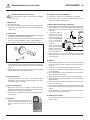
Take Note!
Check the shaft
gap at least once
per year
• In normal operation the gap (A) should be approx. 1
mm. If shaft play (W) is greater then it can be corrected
with washers
• If the
gap (A) is greater than 4 mm then change the
bushings (B) on the inner side of the tine arms. Otherwise
consequent damage can occur to the machine.
Tine arms
Spring tines
• Check the spring tines fastening bolts after the first 10
operating hours and tighten if necessary
From the 2007 model *
An additional spacer (U) will be fitted on the outer tines
(ZA)
- longer bolts will be needed (80 mm)
- for this the bolts will be fitted with the head at the
top
U
ZA
S
* Applies to Eurotop 421A / 421N / 461N / 601 / 691 / 771 / 881

0300 SCHMIERPL_286 - 19 -
FETTFETT
3x (IV)
0,3 Liter
OIL (III)
0300 SCHMIERPLAN (286)
600 cm
OIL (V)
3
1 J
20h
FETT
24x (IV)
FETT
1x (IV)
( … - Bj 1998
FETT
3x (IV)
OIL
OIL
20
1 J
h
FETT
1x (IV)
FETT
4x (IV)
0,3 Liter
OIL (III)
FETT
600 cm
OIL (V)
2
x
(
IV
)
3
1x (IV)
1x (IV)
8
h
FETT

9900-ZENTRAL_LEGENDE-SCHMIERPLAN - 20 -
Schmierplan
X
h alle X Betriebsstunden
40 F alle 40 Fuhren
80 F alle 80 Fuhren
1 J 1 x jährlich
100 ha alle 100 Hektar
FETT FETT
= Anzahl der Schmiernippel
= Anzahl der Schmiernippel
(IV) Siehe Anhang "Betriebsstoffe"
Liter Liter
* Variante
Siehe Anleitung des Herstellers
Smeerschema
X
h alle X bedrijfsuren
40 F alle 40 wagenladingen
80 F alle 80 wagenladingen
1 J 1 x jaarlijks
100 ha alle 100 hectaren
FETT VET
= Aantal smeernippels
= Aantal smeernippels
(IV) Zie aanhangsel "Smeermiddelen"
Liter Liter
* Varianten
zie gebruiksaanwijzing van de fabrikant
Schema di lubrificazione
X
h ogni X ore di esercizio
40 F ogni 40 viaggi
80 F ogni 80 viaggi
1 J volta all'anno
100 ha ogni 100 ettari
FETT GRASSO
= Numero degli ingrassatori
= Numero degli ingrassatori
(IV) vedi capitolo “materiali di esercizio”
Liter litri
* variante
vedi istruzioni del fabbricante
Plan de graissage
X
h Toutes les X heures de service
40 F Tous les 40 voyages
80 F Tous les 80 voyages
1 J 1 fois par an
100 ha tous les 100 hectares
FETT GRAISSE
= Nombre de graisseurs
= Nombre de graisseurs
(IV) Voir annexe "Lubrifiants"
Liter Litre
* Variante
Voir le guide du constructeur
Lubrication chart
X
h after every X hours operation
40 F all 40 loads
80 F all 80 loads
1 J once a year
100 ha every 100 hectares
FETT GREASE
= Number of grease nipples
= Number of grease nipples
(IV) see supplement "Lubrificants"
Liter Litre
* Variation
See manufacturer’s instructions
FETT
Esquema de lubricación
X
h Cada X horas de servicio
40 F Cada 40 viajes
80 F Cada 80 viajes
1 J 1 vez al año
100 ha Cada 100 hectáreas
FETT LUBRICANTE
= Número de boquillas de engrase
= Número de boquillas de engrase
(IV) Véase anexo “Lubrificantes”
Liter Litros
* Variante
Véanse instrucciones del fabricante
Plano de lubrificação
X
h Em cada X horas de serviço
40 F Em cada 40 transportes
80 F Em cada 80 transportes
1 J 1x por ano
100 ha Em cada100 hectares
FETT Lubrificante
= Número dos bocais de lubrificação
= Número dos bocais de lubrificação
(IV) Ver anexo ”Lubrificantes"
Liter Litro
* Variante
Ver instruções do fabricante
I
P
NL
D GBF
E
La pagina si sta caricando...
La pagina si sta caricando...
La pagina si sta caricando...
La pagina si sta caricando...
La pagina si sta caricando...
La pagina si sta caricando...
La pagina si sta caricando...
La pagina si sta caricando...
La pagina si sta caricando...
La pagina si sta caricando...
La pagina si sta caricando...
La pagina si sta caricando...
La pagina si sta caricando...
-
 1
1
-
 2
2
-
 3
3
-
 4
4
-
 5
5
-
 6
6
-
 7
7
-
 8
8
-
 9
9
-
 10
10
-
 11
11
-
 12
12
-
 13
13
-
 14
14
-
 15
15
-
 16
16
-
 17
17
-
 18
18
-
 19
19
-
 20
20
-
 21
21
-
 22
22
-
 23
23
-
 24
24
-
 25
25
-
 26
26
-
 27
27
-
 28
28
-
 29
29
-
 30
30
-
 31
31
-
 32
32
-
 33
33


Pottinger EUROTOP 650 MULTITAST Istruzioni per l'uso
- Categoria
- Mini motozappe
- Tipo
- Istruzioni per l'uso
- Questo manuale è adatto anche per
in altre lingue
Documenti correlati
-
Pottinger EUROTOP 881 A Istruzioni per l'uso
-
-
-
-
-
-
-
-
-