STUDIO DUE STADIO 432 Manuale utente
- Categoria
- Illuminazione di comodità
- Tipo
- Manuale utente

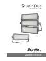
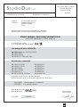
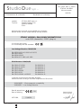
User manual for art. 1950-1951-1952
Manuale d’uso per art. 1950-1951-1952
MONOCHROMATIC
series
Stadio

rel. 03/22 - Studio Due 2
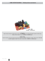
* SURGE PROTECTION MODULE - * Modulo protezione sovratensioni
[ all series ]
High immunity to voltage overloads thanks to the use of a 10KV-20KA Surge Protection Module capable of withstanding
voltage and current pulses up to 10.000Volt and 20.000Ampere.
[ tutta la serie ]
Elevata immunità ai sovraccarichi di tensione grazie all’utilizzo di un Modulo di Protezione contro le Sovratensioni 10KV-20KA
in grado di sopportare impulsi di tensione e corrente fino a 10.000 Volt e 20.000 Ampere.
10KV - 20KA
10.000Volt - 20.000Ampere

rel. 03/22 - Studio Due
3
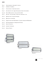
Stadio 432
Stadio 288
Stadio 144
INDEX
Page 4 Safety informations / Informazioni di sicurezza
Page 5 Introduction / Introduzione
Page 7 Technical features / Caratteristiche tecniche
Page 9 Connection to the main supply / Collegamento alla fonte di alimentazione
Page 10 DALI or DMX connections / Connessioni DALI o DMX
Page 11 Box driver - heads connections / Connessioni scatola driver - teste
Page 12 Mounting scheme / Schema di montaggio
Page 13 DMX channels / Canali DMX
Page 14 Example of connections DMX-Controller / Esempi di collegamento DMX-Controller
Page 15 DRS Setup configuration / Configurazione DRS Setup
Page 18 Physical / Dimensioni
Page 20 Standards / Certificazioni
Page 23 Warranty / Garanzia

rel. 03/22 - Studio Due 4
.................................................................................................................. ENG
SAFETY INFORMATION (service personnel)
IMPORTANT !
READ ALL CAUTIONS AND WARNINGS PRIOR TO OPERATE THIS EQUIPMENT.
INSTRUCTION TO PREVENT INJURY OR DAMAGE DUE TO ELECTRIC SHOCK, FIRE, MECHANICAL HAZARDS, DANGEROUS MATTERS.
• PROTECTION AGAINST DANGEROUS MATTERS
At the end of its life, must be collected separately. It shouldn’t be thrown as urban waste and neither released in the environment.
It must be collected from the nearest special waste collection point or consigned to your dealer that provides the service.
The incorrect waste disposal can damage the environment and the people for the presence of dangerous substances.
Sanctions are provided for an unauthorized disposal. ............................................................................................................................................................
• PROTECTION AGAINST FIRE
1) Maintain minimum distance of 0,2 meter to lighted objects.
2) Replace fuses (if present) only with the specified type and rating.
3) Do not install the fixture close to heat sources. Do not lay the connection cable on the fixture when it is warm.
4) Fixture designed to be installed on normally flammable surfaces. .....................................................................................................................................
• PROTECTION AGAINST ELECTRIC SHOCK
1) This equipment must be earthed.
2) Class I equipment. The power supply cord includes a protective earthing conductor as part of the cord.
3) Disconnect power before servicing (service personnel).
4) To replace the LEDs, contact: Studio Due Srls.
5) If the external flexible cable of this appliance is damaged, it must only be replaced by the manufacturer,
its assistance service, or equivalent qualified personnel, in order to avoid dangers. ...........................................................................................................
• PROTECTION AGAINST MECHANICAL HAZARDS
1) Use secondary safety chain when fixing this equipment.
2) The protection screens and the lenses must be replaced with genuine parts only if they are visibly damaged and
their effectiveness has been reduced, for example, by cracks or deep scratches.
3) Do not look directly into the illuminated LEDs of the product for long periods of time. LED lamps can cause eye
damage or irritation. Do not look directly into the light source using an optical instrument that focuses on the light beams.
The device should be positioned so that there is no prolonged observation of the device at a distance of less than 100cm. (RG1 – IEC/TR 62778:2014).
................................................................................................................... ITA
INFORMAZIONI DI SICUREZZA (personale di servizio)
IMPORTANTE !
LEGGERE ATTENTAMENTE TUTTI GLI AVVERTIMENTI PRIMA DI COMPIERE QUALUNQUE OPERAZIONE SU QUESTO APPARECCHIO.
ISTRUZIONI PER PREVENIRE LESIONI O DANNI DOVUTI AL FUOCO, ALLE SCOSSE ELETTRICHE, AI RISCHI MECCANICI ED A SOSTANZE PERICOLOSE.
•PROTEZIONE CONTRO SOSTANZE PERICOLOSE
A fine vita è oggetto di raccolta separata, non gettare nei comuni cassonetti di rifiuti urbani, né tantomeno nell’ambiente.
Può essere consegnato presso i centri di raccolta delle amministrazioni comunali, oppure presso i rivenditori che forniscono questo servizio.
Lo smaltimento errato può causare danni alle persone e all’ambiente per la possibile presenza di sostanze pericolose.
Sono previste sanzioni in caso di smaltimento abusivo dei suddetti prodotti. ..........................................................................................................................
•PROTEZIONE CONTRO IL FUOCO
1) Mantenere la distanza minima di 0,2 metri dagli oggetti illuminati.
2) Sostituire i fusibili (se presenti) solo con altri dello stesso tipo e valore.
3) Non installare il faro vicino fonti di calore. Non appoggiare il cavo di connessione sul faro quando questo è caldo.
4) Questo apparecchio è adatto per il montaggio su superfici normalmente infiammabili. .......................................................................................................
•PROTEZIONE CONTRO SCOSSE ELETTRICHE
1) Questo apparecchio necessita di messa a terra.
2) Apparecchio di Classe I. Il conduttore di protezione deve far parte del cavo di alimentazione.
3) Disconnettere l’alimentazione prima di aprire l’apparecchio (personale di servizio).
4) Per la sostituzione dei LED contattare l’azienda: Studio Due Srls
5) Se il cavo flessibile esterno di questo apparecchio è danneggiato, deve essere sostituito esclusivamente
dal costruttore, dal suo servizio di assistenza, o da personale qualificato equivalente, al fine di evitare pericoli. .................................................................
•PROTEZIONE CONTRO RISCHI MECCANICI
1) Usare la catena di sicurezza supplementare quando installate l’apparecchio.
2) Gli schermi di protezione e le lenti devono essere sostituiti sempre con ricambi originali se sono visibilmente danneggiati
e se la loro efficacia è stata ridotta, per esempio, da fessure o incisioni profonde.
3) Non guardare direttamente nei LED illuminati del prodotto per lunghi periodi di tempo. Le lampade a LED possono
causare danni o irritazione agli occhi. Non guardare direttamente nella sorgente luminosa utilizzando uno strumento
ottico che si concentra sui fasci di luce. L’apparecchio dovrebbe essere posizionato in modo che non sia prevista
un’osservazione prolungata dell’apparecchio ad una distanza inferiore di 100cm. (RG1 – IEC/TR 62778:2014).

rel. 03/22 - Studio Due
5
.................................................................................................................. ENG
INTRODUCTION
CHECK THAT THE FIXTURE HAS NOT BEEN DAMAGED DURING TRANSPORT. IF IT HAS BEEN DAMAGED OR IT DOES NOT WORK, ADDRESS THE
SELLER. WHETHER THE FIXTURE HAS BEEN SHIPPED TO YOU DIRECTLY, PLEASE CONTACT THE SHIPPING COMPANY.
ONLY THE CONSIGNEE (PERSON OR COMPANY) CAN CLAIM FOR THESE DAMAGES.
Thanks for choosing STADIO Monochromatic fixtures.
Our innovative IP66 projector with dedicated optic that guarantees maximum efficiency.
Available in different measures and types:
• STADIO 432 (n.3 heads) - STADIO 288 (n.2 heads) - STADIO 144 (n.1 head). DMX-RDM and DALI or Plug-in versions.
Standard versions are plug-in. All the appliances can be on request dimmable with a separate base and/or Plug-in.
• Standard fixture colour finishing is grey.
• Art. 1950: STADIO 432 > (optional DMX-RDM+DALI interface) • Art. 19501: STADIO 432 Plug-in
• Art. 1951: STADIO 288 > (optional DMX-RDM+DALI interface) • Art. 19511: STADIO 288 Plug-in
• Art. 1952: STADIO 144 > (optional DMX-RDM+DALI interface) • Art. 19521: STADIO 144 Plug-in
To obtain the best performances and for a correct functioning of this unit for the years to come, we suggest you to read carefully this manual before
connecting or putting the fixture into use. By doing so you will gain experience with its commands and connections and you will be easily able to use it.
YOUR REFERENCE
Always remember to give the serial number and to specify the model any time you address the seller for information or assistance.
BASIC KIT
• Fixture
• IP67 Male and Female 4PIN AMPHENOL connectors (without cable)
• User manual
• Studio Due warranty
• CE standards
................................................................................................................... ITA
INTRODUZIONE
CONTROLLATE CHE L’APPARECCHIO NON ABBIA SUBITO ALCUN DANNO DURANTE IL TRASPORTO. SE AVESSE SUBITO DEI DANNI O SE NON DOVESSE
FUNZIONARE, RIVOLGETEVI AL VOSTRO RIVENDITORE. SE L’APPARECCHIO VI È STATO SPEDITO DIRETTAMENTE, RIVOLGETEVI SUBITO ALLA DITTA DI
TRASPORTO.
SOLO IL DESTINATARIO (LA PERSONA O DITTA RICEVENTE L’APPARECCHIO) PUÒ RECLAMARE PER QUESTO TIPO DI DANNI.
Grazie per aver scelto gli apparecchi monocromatici STADIO.
Il nostro innovativo proiettore IP66 con ottica dedicata che garantisce la massima efficienza.
Disponibile in diverse misure e tipologie:
• STADIO 432 (n.3 teste) - STADIO 288 (n.2 teste) - STADIO 144 (n.1 testa). Versioni DMX- RDM e DALI o Plug-in.
Le versioni standard sono plug-in. Tutti gli apparecchi possono essere forniti a richiesta dimmerabili con base separata e/o in versione Plug-in.
• Finitura standard colore grigio.
• Art. 1950: STADIO 432 > (opzionale DMX-RDM+DALI interface) • Art. 19501: STADIO 432 Plug-in
• Art. 1951: STADIO 288 > (opzionale DMX-RDM+DALI interface) • Art. 19511: STADIO 288 Plug-in
• Art. 1952: STADIO 144 > (opzionale DMX-RDM+DALI interface) • Art. 19521: STADIO 144 Plug-in
Per ottenere il meglio delle prestazioni ed un corretto funzionamento negli anni di questa unità, Vi consigliamo di leggere attentamente questo manuale
prima di collegarla e metterla in uso. In questo modo acquisirete familiarità con i suoi comandi e collegamenti affinché possiate utilizzarla facilmente.
VOSTRA REFERENZA
Citate sempre il numero del modello e di serie ogni volta che Vi rivolgete al vostro rivenditore per informazioni o assistenza.
CONFEZIONE BASE
• Apparecchio
• Connettori IP67 Maschio e Femmina 4PIN AMPHENOL (senza cavo)
• Manuale d’uso
• Garanzia Studio Due
• Dichiarazione CE

rel. 03/22 - Studio Due 6
.................................................................................................................. ENG / ITA
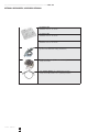
OPTIONAL ACCESSORIES / ACCESSORI OPZIONALI
- art. KB50-15bl
50x50mm lens for 15° beam
- art. KB50-30bl
50x50mm lens for 30° beam
- art. KB50-50bl
50x50mm lens for 50° beam
- art. CLAMP/C
professional aluminium clamp (all fixtures)
- art. SAFETY CHAIN (for STADIO 432 only)
safety steel chain
- art. SAFETY WIRE/C (for STADIO 288 and 144)
safety steel cable, black color + plastic protection

rel. 03/22 - Studio Due
7
.................................................................................................................. ENG / ITA
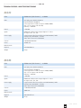
TECHNICAL FEATURES / CARATTERISTICHE TECNICHE
WW W
warm neutral cool
WW W
warm neutral cool
ITEM STADIO 288 [ KEY features ] - 2 HEADS
LEDs 288 high power NICHIA NVSW319
Expected lifetime: 50.000 hrs
Color temperature: 5750K (on request 3000K, 4000K)
CRI: >75 (on request >80 and >90)
Efficency: >140lm/W
Lumen >100.000
Optics PMMA 8N and ultra white tempered glass 15° lenses
On request: 30°, 50°, 120°
Power supply Surge Protection line-line and line-earth 10KA@8/20uS, 10KV
Voltage range: 90-305VAC; 47-63Hz
Active Power Factor: PF>0.95@230V
Current 3.1@230V, 6A@120V
Power 700W max
DMX channels 1
Physical 820x180x455 mm
Weight 21 Kg
ITEM STADIO 432 [ KEY features ] - 3 HEADS
LEDs 432 high power NICHIA NVSW319
Expected lifetime: 50.000 hrs
Color temperature: 5750K (on request 3000K, 4000K)
CRI: >75 (on request >80 and >90)
Efficency: >140lm/W
Lumen >150.000
Optics PMMA 8N and ultra white tempered glass 15° lenses
On request: 30°, 50°, 120°
Power supply Surge Protection line-line and line-earth 10KA@8/20uS, 10KV
Voltage range: 90-305VAC; 47-63Hz
Active Power Factor: PF>0.95@230V
Current 4.65@230V, 9A@120V
Power 1050W max
DMX channels 1
Physical 816x560x690 mm
Weight 39 Kg

rel. 03/22 - Studio Due 8
example of
label on the rear
of the fixture
WW W
warm neutral cool
.................................................................................................................. ENG / ITA
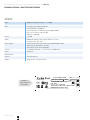
TECHNICAL FEATURES / CARATTERISTICHE TECNICHE
ITEM STADIO 144 [ KEY features ] - 1 HEAD
LEDs 144 high power NICHIA NVSW319
Expected lifetime: 50.000 hrs
Color temperature: 5750K (on request 3000K, 4000K)
CRI: >75 (on request >80 and >90)
Efficency: >140lm/W
Lumen >50.000
Optics PMMA 8N and ultra white tempered glass 15° lenses
On request: 30°, 50°, 120°
Power supply Surge Protection line-line and line-earth 10KA@8/20uS, 10KV
Voltage range: 90-305VAC; 47-63Hz
Active Power Factor: PF>0.95@230V
Current 1.55@230V, 3A@120V - Inrush current: 120A@230V
Power 350W max
DMX channels 1
Physical 768x136x310 mm
Weight 10 Kg (head) - 3 Kg (power box)
art. 1952 STADIO 144 RDM
made in Italy
SN
QC
WI-FI
n.144 LEDs 5000K Optics /
DMX-RDM, DALI (dimmer 20-100%)
100-277V~; 50-60Hz 330W
IP 66 - IK 08
Ta -25°C +40°C Tc 80°C max
Surge protection: 5KV line-line / 10KV line-earth
Disconnect the unit from power before servicing.
DALI
DMX

rel. 03/22 - Studio Due
9
MAIN IN
Ingresso rete
.................................................................................................................. ENG / ITA
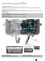
CONNECTION TO THE MAIN POWER / CONNESSIONE ALLA RETE ELETTRICA
This equipment must be earthed.
Class I equipment. The power supply cord includes a protective earthing conductor as part of the cord.
IMPORTANT: to ensure the protection rating of the fixture, in case of replacement of the conductor cable, refer to the CONDUCTOR SIZE TABLE
Questo apparecchio necessita di messa a terra.
Apparecchio di Classe I. Il conduttore di protezione deve far parte del cavo di alimentazione.
IMPORTANTE: per garantire il grado di protezione dell’apparecchio, in caso di sostituzione del cavo di alimentazione, fare riferimento alla TABELLA
SEZIONE CONDUTTORE.
ATTENTION - HIGH VOLTAGE!
ALWAYS DISCONNECT THE MAINS SUPPLY BEFORE ACCESS TO THE CONNECTION AREA.
ATTENZIONE - ALTA TENSIONE!
SCOLLEGARE SEMPRE L’ALIMENTAZIONE PRIMA DI APRIRE IL VANO DEI COLLEGAMENTI.
CONDUCTOR SIZES / SEZIONE CONDUTTORE
(length / lunghezza < 20mt.)
MAINS VOLTAGE CROSS SELECTIONAL AREAS
100-240Vac 3X1,5 mm2 (minimum)
POWER INPUT/
INGRESSO ALIMENTAZIONE ø 6 - 12mm
BROWN / 100/240Vac - 50-60Hz
BLUE / NEUTRAL
GREEN-YELLOW / GROUND
MAIN IN CONNECTION
UNIVERSAL MAIN VOLTAGE
100-240V.~ / 50-60Hz
PIN SIGNAL
(L) Line
(N) Neutral
(G) Ground
ATTENTION - RESINATED WIRING !
DO NOT TAMPER THE GLANDS OR CHANGE THE WIRING.
ATTENZIONE - CABLAGGI RESINATI !
NON MANOMETTERE I SERRACAVI O MODIFICARE LE CONNESSIONI.

rel. 03/22 - Studio Due 10
4pin DMX OUT
IP67 AMPHENOL female connector
(included)
Connettore femmina
(incluso)
4pin DMX IN
IP67 AMPHENOL male connector
(included)
Connettore maschio
(incluso)
.................................................................................................................. ENG / ITA
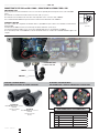
CONNECTION TO THE DMX and DALI SIGNAL / CONNESSIONE AL SEGNALE DMX e DALI
DMX TERMINAL LINE
The wrong connection of the terminal line or its non-connection are probably the most frequent reasons of the lower DMX
signal.
The terminator is a terminal resistor fitted at the end of the cable. (see pict. 1)
The terminal resistor should have the same value as the impedance of the connection cable (120 Ohm).
It is recommanded that all DMX 512 systems have the terminal resistor fitted in the end of DMX line.
TERMINALE LINEA DMX
L’incorretto o il mancato collegamento del terminale di linea è probabilmente la più comune causa del difettoso funzionamento
della linea DMX.
Il terminale di linea DMX consiste in una resistenza posta alla fine della linea. (vedere fig. 1)
La resistenza terminale dovrebbe avere lo stesso valore dell’impedenza del cavo di collegamento (120 Ohm).
E’ raccomandato per tutti i sistemi DMX 512, di inserire il teminale di linea nel connettore di uscita DMX dell’ultimo apparecchio
collegato.
DMX-DALI CONNECTION
PIN DMX-RDM SIGNAL DALI SIGNAL
1SHIELD DALI1
2N.C. DALI2
3DMX - N.C.
4DMX + N.C.
pict. 1
Termination resistor
Terminale di linea
120 Ohm
4
3
n. 2 CONNECTORS 4PIN
n.2 CONNETTORI 4PIN
DMX IN
DMX OUT
1
2
3
4
1
2
3
4
REAR VIEW OF WEIPU TYPE CONNECTORS
FEMALE MALE
ATTENTION - RESINATED WIRING !
DO NOT TAMPER THE GLANDS OR CHANGE THE WIRING.
ATTENZIONE - CABLAGGI RESINATI !
NON MANOMETTERE I SERRACAVI O MODIFICARE LE CONNESSIONI.

rel. 03/22 - Studio Due
11
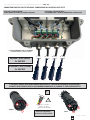
n. 4 OUT CONNECTORS 3PIN already WIRED
n.4 CONNETTORI OUT 3PIN già CABLATI
ATTENTION - RESINATED WIRING !
DO NOT TAMPER THE GLANDS OR CHANGE THE WIRING.
ATTENZIONE - CABLAGGI RESINATI !
NON MANOMETTERE I SERRACAVI O MODIFICARE LE CONNESSIONI.
.................................................................................................................. ENG / ITA
CONNECTION FROM THE BOX TO THE HEADS / CONNESSIONE DALLA SCATOLA ALLE TESTE
RED / + POLARITY
BLACK / - POLARITY
GREEN-YELLOW / GROUND
WARNING !! HIGH TENSION
4 x 450 VDC
ATTENZIONE !! ALTA TENSIONE
4 x 450 VDC
G
LN
FEMALE
MALE
IF YOU NEED TO MAKE ADDITIONAL CONNECTION CABLES (C), FOLLOW THE DESCRIBED SPECIFICATIONS /
SE DOVETE REALIZZARE DEI CAVI DI COLLEGAMENTO AGGIUNTIVI (C), SEGUIRE LE SPECIFICHE DESCRITTE
L
N
G
!
Check the right polarity /
Verificare la corretta polarità
C

rel. 03/22 - Studio Due 12
.................................................................................................................. ENG / ITA
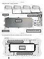
WALL MOUNTING OF THE DRIVER BOX / MONTAGGIO A MURO DELLA SCATOLA DEI DRIVER
LASCIARE ALMENO 10 CM LIBERI SU OGNI LATO
LEAVE AT LEAST 10 CM FREE ON EACH SIDE
WALL / MURO
MAIN IN
Ingresso rete
DMX IN and
DMX OUT
Standard 3x1,5mm cable /
Cavo standard 3x1,5mm
Standard DMX cable /
Cavo standard DMX
DRIVER BOX /
SCATOLA DRIVER
DRIVE BOX /
SCATOLA DRIVER
668x245x80mm
Standard 3x1mm cable: 2 colours + green-yellow /
Cavo standard 3x1mm: 2 colori + giallo-verde
.................................................................................................................. ENG / ITA
CONNECTION SCHEME / SCHEMA DI MONTAGGIO
Additional connection cable (C) /
Cavo di connessione addizionale (C) C

rel. 03/22 - Studio Due
13
DMX
512
8 BIT FUNCTION 0 31 63 95 127 159 191 233 255
CH1 DIMMER
DIMMER from 20% to 100% on CH1
.................................................................................................................. ENG / ITA
DMX CHANNELS and DALI LINE / CANALI DMX e LINEA DALI
- (*) DMX line for Dimmable version. (setting 1ch)
--------------------------------------------------------------------------------------------------------------
- (*) linea DMX versione Dimmerabile. (settaggio 1ch)
20% 100%
DALI

rel. 03/22 - Studio Due 14
.................................................................................................................. ENG / ITA
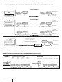
EXAMPLE OF CONNECTION DMX CONTROLLER - FIXTURES / ESEMPIO DI COLLEGAMENTO CENTRALINA - FARI
DMX
fixture 1 fixture 2 fixture 3 fixture 4
TL
NORMAL
Address
set-up 3ch
=C001
Address
set-up 3ch
=C004
Address
set-up 3ch
=C007
Address
set-up 3ch
=C010
fixture 2 fixture 3 fixture 4
TL
MASTER / SLAVE
Set up = MASTER set-up = SLAVE set-up = SLAVE set-up = SLAVE
fixture 1
NORMAL AND MASTER/SLAVE FUNCTIONS / FUNZIONI NORMAL E MASTER/SLAVE
Example 1/ Esempio 1
DMX
Last fixture/
Ultimo apparecchio
Termination resistor/
Terminale di linea
Example 2 / Esempio 2
DMX
line 1 / linea 1
line 2 / linea 2
DMX 1 out DMX 2 out
Connection controller-spot to
1 DMX 512 output over 150 mt. long
Collegamento centralina-spot ad una sola
linea di uscita DMX 512 lunga oltre 150 mt.
LINE > 150 mt. (with microphonic or audio cable)
LINEA > 150 mt. (con cavo microfonico o audio)
DMX
Example 3 / Esempio 3
SIGNAL AMPLIFIER
AMPLIFICATORE
DI SEGNALE
DMX out
DMX out
TL=
Terminal Line
for example fixture set-up at 3 channels
TL
TL
TL
TL
fixture /
apparecchio
fixture /
apparecchio fixture /
apparecchio
fixture /
apparecchio
fixture /
apparecchio
fixture /
apparecchio
fixture /
apparecchio
fixture /
apparecchio
fixture /
apparecchio fixture /
apparecchio
fixture /
apparecchio
fixture /
apparecchio
fixture /
apparecchio
fixture /
apparecchio fixture /
apparecchio
fixture /
apparecchio
Last fixture/
Ultimo apparecchio
Termination resistor/
Terminale di linea
fixture /
apparecchio
fixture /
apparecchio fixture /
apparecchio
fixture /
apparecchio
Last fixture/
Ultimo apparecchio
Termination resistor/
Terminale di linea
Last fixture/
Ultimo apparecchio
Termination resistor/
Terminale di linea
fixture /
apparecchio fixture /
apparecchio

rel. 03/22 - Studio Due
15
.................................................................................................................. ENG
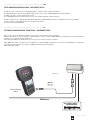
SETUP AND CONFIGURATION BY DRS - DMX REMOTE SETUP
The DRS it’s a new concept of professional LED Lighting fixtures suitable for outdoor permanent installations.
The LED Lighting fixtures can be driven via DMX through a specific electronic device, the DRS DMX Remote Setup, that grant the
possibility to set up the scenarios and the games remotely.
These LED Lighting fixtures have installed on board a series of programs including the stand alone function.
The DRS is a simple set up commander that linked with the DMX input of a LED Lighting fixture allow to program all the functions of the luminaire.
It’s than possible to assign the DMX channel or use the Master/Slave function.
The device is powered through battery.
DRS è il nuovo concetto dell’illuminazione LED per uso professionale nelle installazioni esterne permanenti.
Gli apparecchi LED possono essere controllati e configurati tramite uno specifico controller: il DRS, DMX Remote Setup, il quale consente di programmare e
configurare scene e giochi di luce in modalità remota.
Questi apparecchi LED hanno installati a bordo una serie di giochi che includono la funzione stand alone.
Il DRS, DMX Remote Setup, è un semplice set-up commander che collegato via DMX ad un’apparecchio consente la sua programmazione e configurazione.
E’ possibile assegnare agli apprecchi collegati i canali DMX o utilizzazre la funzione Master/Slave.
Il DRS è alimentato a batterie.
DMX line
XRL - 4pin
connector
MAIN Power
Powered through
battery
RDM CONSOLE
.................................................................................................................. ITA
SETTAGGIO E CONFIGURAZIONE TRAMITE DRS - DMX REMOTE SETUP
example view

rel. 03/22 - Studio Due 16
.................................................................................................................. ITA
SETTAGGIO E CONFIGURAZIONE TRAMITE DRS - DMX REMOTE SETUP
Per effettuare la programmazione dei vari parametri di un apparecchio, è necessario procedere come segue:
• Disconnettere l’apparecchio da configurare da altri dispositivi DMX/RDM
• Collegare il cavo DMX dell’apparecchio da configurare, al programmatore DRS
• Accendere il programmatore DRS ed attendere che visualizzi la scritta 8888
• Se il programmatore DRS individua un dispositivo DRS compatibile, visualizza per qualche istante la scritta Conn e,
successivamente, visualizza il nome dell’apparecchio e la relativa versione software
• Se il programmatore DRS non individua alcun dispositivo DRS compatibile o è presente qualche malfunzionamento il display
visualizzerà la scritta SCAn
• Una volta terminata la sequenza di riconoscimento, viene visualizzato il primo menu dell’apparecchio
• I pulsanti UP/DOWN permettono di scorrere la lista dei menu
• Il pulsante ENTER permettere di entrare in un menu o di confermare una opzione in caso di lampeggio del parametro
• Il pulsante ESC annulla una operazione o torna al livello di menu inferiore.
.................................................................................................................. ENG
SETUP AND CONFIGURATION BY DRS - DMX REMOTE SETUP
To make the set-up of the various fixture parameter, proceed as follow:
•Disconnect the fixture to set-up from the other DMX/RDM devices
• Connect the DMX cable of the fixture to the DRS commander
• Switch on the DRS commander and wait for the 8888 sign
• If the DRS commander detects a compatible DRS device, displays shortly the Conn written and afterwards,
displays the name of the fixture and its software version.
• If the DRS commander dont’ detects any compatible DRS device or is present any malfunction, the display
shows the SCAn written
• When the detection sequence is finished, the display shows the first menu
• The UP/DOWN buttons allow to scroll forward/backward the menu list
• The ENTER button allow to confirm the selected option (if the parameter is flashing)
• The ESC button allow to delete the operation and return to a previus menu level
dimmable version only / solo versione dimmerabile

rel. 03/22 - Studio Due
17
.................................................................................................................. ENG / ITA
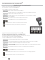
DRS MENU’ LIST / ELENCO MENU DRS
Switching on the fixture you can see the model and the software version. For example:
All’accensione, viene visualizzato il modello di apparecchio e la versione software. Per esempio:
--> MP-240 --> 1_00
than it’s shown the fist menu
poi viene visualizzato il primo menu
Address (Addr) Set the DMX address
Imposta l’indirizzo DMX
Auto Mode (ModE) Set the DMX, SLAVE or MASTER mode
Imposta la modalità DMX, SLAVE o MASTER
(no, SL, Pr01…Prxx)
Auto Speed (PrSP) Set the preset execution speed
Imposta la velocità di esecuzione dei giochi interni
( -400%…+400%)
N. Channels (nChn) Set the DMX channels of the fixture
Imposta il numero di canali DMX dell’apparecchio
(13, 10, 6, 3 etc.)
Wireless enable (ULEn) Enable or disable the wireless reception
Consente o non consente la ricezione wireless (ON / OFF)
The cable reception is disabled / La ricezione via cavo viene disabilita
Wireless unlink (ULPA) Remove the link from the fixture to the associated transmitter (PA?)
Elimina il link tra l’apparecchio e il trasmettitore al quale è stato associato
Wireless bridge (ULbr) If wireless is ON, enable the transmission of the received data by cable to the
other fixtures / Se il wireless è attivo, consente la trasmissione dati agli altri
apprecchi collegati via cavo. (ON / OFF)
Smooth Dimming (SMth) Set the interpolation type for the smooth dimming function
Imposta il tipo di interpolazione per la funzione smooth dimming
(OFF, Sd1, Sd2, Sd3)
Halogen Simulation (HALS) Set the alogen simulation function mode
Imposta il funzionamento della modalità simulazione lampada alogena
(OFF, Mod1, Mod2)
CYM Emulation (CYMS) Set the fixture to work in CYM or RGB emulation system
Imposta l’apparecchio per funzionare come emulatore di sistema CYM o RGB
(OFF -->RGBW, On -->CYM)
Flicker free function (FLcr)
Select the value f1 .. f2
Selezionate il valore desidarato f1 .. f2
Test (tESt) Enables the test of the fixture and execute a factory program to check
the right functioning
Abilita il test dell’apparecchio ed esegue un programma di fabbrica per
verificarne il funzionamento
(OFF, On)
Reset (rSEt) Execute a reset of the electronic section
Esegue un reset della parte elettronica
Format (FrMt) Restore the factory setting (Require confirmation)
Ripristina le impostazioni di fabbrica (Viene chiesta conferma)

rel. 03/22 - Studio Due 18
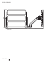
PHYSICAL / DIMENSIONI
STADIO 432
816
690
560
100

rel. 03/22 - Studio Due
19
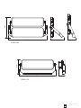
820
455
290 180
768
310
136
STADIO 288
STADIO 144

rel. 03/22 - Studio Due 20
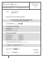
STADIO 432 RDM + DALI MONOCHROMATIC IP66
code 1950 (dimmable) - 19501 (plug-in)
è conforme alle norme:
is in conformity with the standard:
e quindi ai requisiti essenziali delle Direttive:
and therefore according to essential requirement of Directives:
EN 61000-4-2
EN 61000-4-3
EN 61000-4-4
EN 61000-4-5
EN 61000-4-6
EN 61000-4-11
2004/108/EC – Electromagnetic compatibility
2006/95/EC – Low Voltage directive
ECM Directive: 2014/30/EU
EN 61000-3-2:2014
EN 61000-3-3:2013
EN 61547:2009
EN 55103-2:2009
EN 55015:2013
EN 55103-1:2009 + A1:2012
Low Voltage Directive: 2014/35/EU
EN 60529:1991 + A1:2000 + A2:2013
EN 62471:2008
EN 60598-1:2015
EN 60598-2-17:1989 + A2:1991
La ditta:
The firm:
dichiara sotto la propria responsabilità che il prodotto:
declare under our sole responsability that the product:
VITERBO, 13/06/19
19
Data di apposizione
Date of marking
Doc. 1950 REV 1 - 06/19
STADIO 432 RDM
Monochromatic
06/2019
STUDIO DUE light s.r.l.
Strada Poggino, 100
01100 VITERBO
ITALY
Dichiarazione di conformità Declaration of conformity
StudioDue
light s.r.l.
PAOLO SENSI
General Manager
La pagina sta caricando ...
La pagina sta caricando ...
La pagina sta caricando ...
La pagina sta caricando ...
-
 1
1
-
 2
2
-
 3
3
-
 4
4
-
 5
5
-
 6
6
-
 7
7
-
 8
8
-
 9
9
-
 10
10
-
 11
11
-
 12
12
-
 13
13
-
 14
14
-
 15
15
-
 16
16
-
 17
17
-
 18
18
-
 19
19
-
 20
20
-
 21
21
-
 22
22
-
 23
23
-
 24
24


STUDIO DUE STADIO 432 Manuale utente
- Categoria
- Illuminazione di comodità
- Tipo
- Manuale utente
in altre lingue
- English: STUDIO DUE STADIO 432 User manual