
USER MANUAL
CEILING FAN VENTILADOR DE TECHO


4
INDEX
ENGLISH
LIST OF PARTS 6
INSTALLATION PREPARATION 7
INSTALLATION INSTRUCTIONS 7
Security instructions 7
MOUNTING BRACKET ATTACHMENT 8
REMOTE CONTROL 8
REMOTE CONTROL CONNECTION 9
RECEIVER PLACEMENT 9
MOUNTING THE BLADES 10
ASSEMBLING THE CONNECTION PANEL 10
LED PANEL AND DECORATIVE SCREEN 10
CEILING FAN WITH LED LIGHT 10
ESPAÑOL
LISTA DE PARTES 12
PREPARACIÓN DE LA INSTALACIÓN 13
INSTRUCCIONES DE SEGURIDAD 13
INSTRUCCIONES DE INSTALACIÓN 13
FIJACIÓN DEL SOPORTE DE MONTAJE 14
MANDO A DISTANCIA 14
CONEXIÓN DEL MANDA A DISTANCIA 15
COLOCACIÓN DEL RECEPTOR 15
MONTAJE DE LAS ASPAS 16
ENSAMBLAJE DEL PANEL DE CONEXIONES 16
PANEL LED Y PANTALLA DECORATIVA 16
VENTILADOR DE TECHO CON LUZ LED 16
PORTUGUÊS
LISTA DE PEÇAS 18
PREPARAÇÃO DE INSTALAÇÃO 19
INSTRUÇÕES DE SEGURANÇA 19
INSTRUÇÕES DE INSTALAÇÃO 19
ANEXO DO SUPORTE DE MONTAGEM 20
CONTROLE REMOTO 20
CONEXÃO DE CONTROLE REMOTO 21
COLOCAÇÃO DO RECEPTOR 21
MONTAGEM DAS LÂMINAS 22
MONTAGEM DO PAINEL DE CONEXÃO 22
PAINEL DE LED E TELA DECORATIVA 22
VENTILADOR DE TETO COM LUZ LED 22
FRANÇAIS
LISTE DES PIÈCES 24
PRÉPARATION À L'INSTALLATION 25
CONSIGNES DE SÉCURITÉ 25
INSTRUCTIONS D'INSTALLATION 25
FIXATION DU SUPPORT DE MONTAGE 26
TÉLÉCOMMANDE 26
CONNEXION DE LA TÉLÉCOMMANDE 27
EMPLACEMENT DU RÉCEPTEUR 27
MONTAGE DES LAMES 28
ASSEMBLAGE DU PANNEAU DE CONNEXION 28
PANNEAU LED ET ÉCRAN DÉCORATIF 28
VENTILATEUR DE PLAFOND LED 28

5
ITALIANO
ELENCO DELLE PARTI 30
PREPARAZIONE ALL'INSTALLAZIONE 31
ISTRUZIONI PER L'INSTALLAZIONE 31
ISTRUZIONI DI SICUREZZA 31
ATTACCO STAFFA DI MONTAGGIO 32
TELECOMANDO 32
CONNESSIONE TELECOMANDO 33
POSIZIONAMENTO DEL RICEVITORE 33
MONTAGGIO LAME 34
MONTAGGIO DEL PANNELLO DI CONNESSIONE 34
PANNELLO LED E SCHERMO DECORATIVO 34
VENTILATORE DA SOFFITTO CON LUCE LED 34
DEUTSCH
TEILELISTE 36
INSTALLATIONSVORBEREITUNG 37
SICHERHEITSHINWEISE 37
INSTALLATIONSANLEITUNG 37
MONTAGEHALTERUNG BEFESTIGUNG 38
FERNBEDIENUNG 38
ANSCHLUSS DER FERNBEDIENUNG 39
EMPFÄNGERPLATZIERUNG 39
MONTAGE DER KLINGEN 40
MONTAGE DES ANSCHLUSSPANELS 40
LED-PANEL UND DEKORATIVER BILDSCHIRM 40
DECKENLÜFTER MIT LED-BELEUCHTUNG 40
NEDERLANDS
LIJST MET ONDERDELEN 42
INSTALLATIE VOORBEREIDING 43
BEVEILIGINGSINSTRUCTIES 43
INSTALLATIE INSTRUCTIES 43
MONTAGEBEUGEL BEVESTIGING 44
AFSTANDSBEDIENING 44
AANSLUITING AFSTANDSBEDIENING 45
PLAATSING ONTVANGER 45
DE MESSEN MONTEREN 46
HET VERBINDINGSPANEEL MONTEREN 46
LED-PANEEL EN DECORATIEF SCHERM 46
PLAFONDVENTILATOR MET LED-LICHT 46
POLSKI
LISTA CZĘŚCI 48
PRZYGOTOWANIE DO INSTALACJI 49
INSTRUKCJE BEZPIECZEŃSTWA 49
INSTRUKCJE INSTALACJI 49
MOCOWANIE WSPORNIKA MONTAŻOWEGO 50
ZDALNE STEROWANIE 50
POŁĄCZENIE ZDALNEGO STEROWANIA 51
UMIESZCZENIE ODBIORNIKA 51
MONTAŻ NOŻY 52
MONTAŻ PANELU POŁĄCZENIOWEGO 52
PANEL LED I EKRAN DEKORACYJNY 52
WENTYLATOR SUFITOWY OŚWIETLENIEM LED 52
INDEX

ENGLISH
6
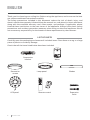
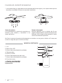
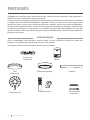
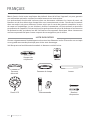
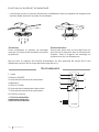
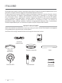
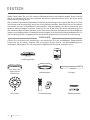
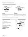
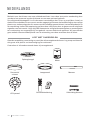
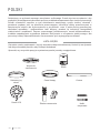
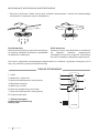
Remote control Expansion
bolts
Blades
Suspension
bracket Motor
LED panel
Decorative
screen Lamp panel
Thank you for choosing our ceiling fan. Before using the appliance, and to ensure the best
use, please read these instructions carefully.
The safety precautions included in this document reduce the risk of death, injury, and
electric shock when properly followed. Keep the manual in a safe place for future reference,
along with the complete warranty card, sales receipt, and package. If applicable, please
forward these instructions to the next owner of the appliance. Always follow basic safety
precautions and accident prevention measures when using an electrical appliance. We do
not assume any responsibility for the breach of these requirements by the customer.
LIST OF PARTS
Carefully open the packaging and remove all included items. Place them on a rug or a large
piece of plastic to avoid any damage.
Check that all the items listed below have been included.
ENGLISH

7
ENGLISH
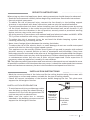
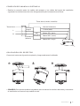
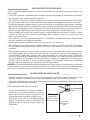
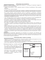
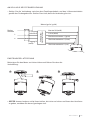
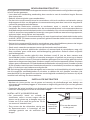
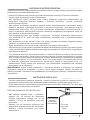
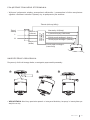
• To avoid personal injury and damage, make
sure the place to hang the sheets leaves a
clearance of 2.3 m from the ground and 76
cm from any walls or obstructions.
• Make sure the outlet box is securely
attached to the building structure and can
support the full weight of the fan.
INSTALLATION PREPARATION
76 cm of
separation
between
the wall or
obstacle. 2.3 m from
the blades
to the
ground
• Mark the correct position of the holes and x the ceiling bracket using the screws with
metal plugs or screws and washers suitable for the type of ceiling chosen.
• Check the correct installation of the bracket before hanging the fan. This plate must
support the full weight of the fan.
INSTALLATION INSTRUCTIONS
When using any electrical appliance, basic safety precautions should always be observed.
• Read this entire manual carefully before beginning installation. Save these instructions.
• Use only original spare parts.
• To reduce the risk of personal injury, connect the fan directly to the building support
structure in accordance with these instructions and use only the supplied hardware.
• To avoid possible electrical shock, before installing your fan, disconnect power by turning
off the circuit breakers in the outlet box and the associated wall switch location. If you
cannot lock the circuit breakers in the off position, securely attach a prominent warning
device, such as a tag, to the service panel.
• All wiring must be in accordance with national and local electrical codes and ANSI / NFPA
70. If you are unfamiliar with wiring, contact a qualied electrician.
• To reduce the risk of personal injury, do not bend the blade clamping system when
installing, balancing, or cleaning the fan.
• Never insert foreign objects between the rotating fan blades.
• To reduce the risk of re, electric shock, or motor damage, do not use a solid state speed
control with this fan. Use only original speed controls.
• This appliance can be used by children from 8 years of age and by people with reduced
physical, sensory or mental abilities or lack of experience and knowledge if they have
been supervised or instructed in the safe use of the appliance and understand the dangers
involved. Children must not play with the appliance. Children should not perform cleaning
or maintenance unless they are over 8 years old and supervised. Close supervision is
necessary when any appliance is used by or near children.
TIP: The important safety precautions and instructions in the manual are not intended to cover
all possible conditions and situations that may occur. It should be understood that common
sense and caution are necessary factors in the installation and operation of this fan.
SECURITY INSTRUCTIONS

ENGLISH
8
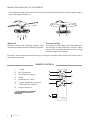
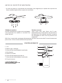
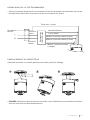
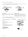
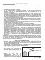
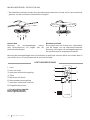
MOUNTING BRACKET ATTACHMENT
• The outlet box and beam must be securely mounted and capable of reliably supporting at
least the weight of the fan.
Wood roof
Securely attach the mounting bracket with
wood screws and washers to the ceiling joints.
Concrete ceiling
Drill holes with an 8mm drill, depending on
the length of the expansion screws. Next,
secure the mounting bracket to the ceiling
with the expansion screws.
Do not x the mounting bracket directly on ceilings less than 10mm thick to avoid the risk of
the screw loosening.
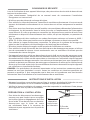
1. **Light
2. On / off button
3. Fan intensity control
4. Timer
5. Batteries (2 x AAA)
6. **Color temperature control
7. **Fan intensity control
8. Inverse function
REMOTE CONTROL
** Function only available
when the LED board is
installed.

9
ENGLISH
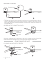
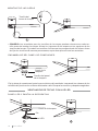
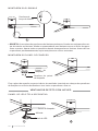
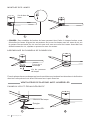
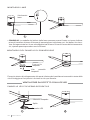
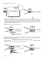
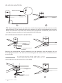
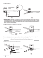
Attach the motor to the left hook, and then lead the wiring.
• TIP: Someone else should help you hold the ladder and hand you the fan after you get on it.
123
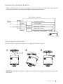
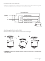
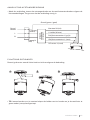
REMOTE CONTROL CONNECTION
RECEIVER PLACEMENT
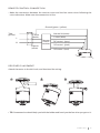
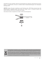
• Make the connection between the receiver wires and the fan motor wires following the
color indications. Make sure the connection is rm.
DC motor L (red)
Remote
control
receiver
Take
ground
L
N
L input
(black)
Input N
(white)
Neutral N (white)
L clear (blue)
DC motor L (pink)
DC motor L (gray)
Ground (green / yellow)

ENGLISH
10
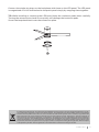
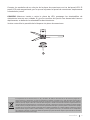
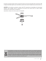
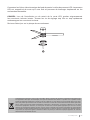
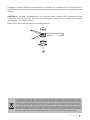
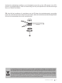
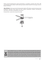
Blade arm screw
12
MOUNTING THE BLADES
• TIP: Blade bolt washers can be attached to each bolt prior to installing blades. Align the
juicers on the blades with the screw holes on the motor. Tighten all the screws once you
have hooked the blades. Before permanently xing the screws, repeat this process with
the remaining ones.
Lamp panel
Lamp panel
screw
ASSEMBLING THE CONNECTION PANEL
Attach the connection plate to the bottom of the fan by inserting the heads of the xing
screws into the holes intended for this. Drive in the screws and then secure them.
Pin
LED panel
12
CEILING FAN WITH LED LIGHT
LED PANEL AND DECORATIVE SCREEN
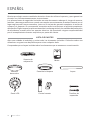
Lamp panel

11
ENGLISH
Connect the single-pin plugs on the backplane with those on the LED panel. The LED panel
is magnetized so it will be attached to the patch panel simply by snapping them together.
TIP: While installing or removing the LED board, keep the insulation pads intact carefully.
Turning the setscrews too hard or too quickly will damage the insulation pads.
Screw the lampshade back onto the connection plate.
3
In compliance with Directives: 2012/19/EU and 2015/863/EU on the restriction of the use of dangerous substances in elec-
tric and electronic equipment as well as their waste disposal. The symbol with the crossed dustbin shown on the package
indicates that the product at the end of its service life shall be collected as separate waste. Therefore, any products that
have reached the end of their useful life must be given to waste disposal centres specialising in separate collection of
waste electrical and electronic equipment, or given back to the retailer at the time of purchasing new similar equipment,
on a one for one basis. The adequate separate collection for the subsequent start-up of the equipment sent to be recycled,
treated and disposed of in an environmentally compatible way contributes to preventing possible negative effects on the
environment and health and optimises the recycling and reuse of components making up the apparatus. Abusive disposal
of the product by the user involves application of the administrative sanctions according to the laws.

12 ESPAÑOL
Control remoto Tornillos de
expansión
Aspas
Soporte de
suspensión
Panel LED
Pantalla
decorativa Panel de la lámpara
Gracias por elegir nuestro ventilador de techo. Antes de utilizar el aparato, y para garantizar
el mejor uso, lea atentamente estas instrucciones.
Las precauciones de seguridad incluidas en este documento reducen el riesgo de muerte,
lesiones y descargas eléctricas cuando se cumplen correctamente. Guarde el manual en un
lugar seguro para futuras consultas, junto con la tarjeta de garantía completa, el recibo de
compra y el paquete. Si corresponde, transmita estas instrucciones al próximo propietario
del aparato. Siga siempre las precauciones básicas de seguridad y las medidas de prevención
de accidentes cuando utilice un aparato eléctrico. No asumimos ninguna responsabilidad
por el incumplimiento de estos requisitos por parte del cliente.
LISTA DE PARTES
Abra con cuidado el embalaje y retire todos los elementos incluidos. Colócalos sobre una
alfombra o un gran trozo de plástico para evitar cualquier daño.
Compruebe que se hayan incluido todos los elementos que se enumeran a continuación.
ESPAÑOL
Motor

13
ESPAÑOL
• Para evitar lesiones personales y daños,
asegúrese de que el lugar para colgar las
hojas deje un espacio libre de 2,3 m del suelo
y 76 cm de cualquier pared u obstrucción.
• Asegúrese de que la caja de distribución
esté bien sujeta a la estructura del edicio
y pueda soportar todo el peso del ventilador.
PREPARACIÓN DE LA INSTALACIÓN
76 cm de
separación
entre la pared
u obstáculo. 2,3 m de
las aspas al
suelo
Al utilizar cualquier aparato eléctrico, siempre se deben observar las precauciones básicas
de seguridad.
• Lea todo este manual detenidamente antes de comenzar la instalación. Guarde estas
instrucciones.
• Utilice únicamente repuestos originales.
• Para reducir el riesgo de lesiones personales, conecte el ventilador directamente a la
estructura de soporte del edicio de acuerdo con estas instrucciones y use solo el hardware
suministrado.
• Para evitar una posible descarga eléctrica, antes de instalar su ventilador, desconecte
la energía apagando los disyuntores de la caja de salida y la ubicación del interruptor de
pared asociado. Si no puede bloquear los disyuntores en la posición de apagado, sujete
rmemente un dispositivo de advertencia prominente, como una etiqueta, al panel de
servicio.
• Todo el cableado debe estar de acuerdo con los códigos eléctricos nacionales y locales y
con ANSI / NFPA 70. Si no está familiarizado con el cableado, contacte con un electricista
cualicado.
• Para reducir el riesgo de lesiones personales, no doble el sistema de sujeción de las aspas
al instalar, equilibrar o limpiar el ventilador.
• Nunca inserte objetos extraños entre las aspas giratorias del ventilador.
• Para reducir el riesgo de incendio, descarga eléctrica o daños al motor, no utilice un control
de velocidad de estado sólido con este ventilador. Utilice solo controles de velocidad
originales.
• Este electrodoméstico puede ser utilizado por niños a partir de 8 años y personas con
capacidades físicas, sensoriales o mentales reducidas o con falta de experiencia y
conocimiento si se les ha supervisado o instruido sobre el uso del electrodoméstico de
manera segura y comprenden las peligros involucrados. Los niños no deben jugar con el
aparato. Los niños no deben realizar la limpieza ni el mantenimiento, a menos que sean
mayores de 8 años y estén supervisados. Es necesaria una estrecha supervisión cuando
cualquier aparato es utilizado por niños o cerca de ellos.
CONSEJO: Las importantes precauciones e instrucciones de seguridad que aparecen en
el manual no pretenden cubrir todas las posibles condiciones y situaciones que pueden
ocurrir. Debe entenderse que el sentido común y la precaución son factores necesarios en la
instalación y operación de este ventilador.
• Marcar la posición correcta de los oricios y jar el soporte de techo mediante los tornillos
con taco metálico o tornillos y arandelas adecuados al tipo de techo elegido.
• Verique la correcta instalación del soporte antes de colgar el ventilador. Esta placa debe
soportar todo el peso del ventilador.
INSTRUCCIONES DE INSTALACIÓN
INSTRUCCIONES DE SEGURIDAD

14 ESPAÑOL
FIJACIÓN DEL SOPORTE DE MONTAJE
• La caja de salida y la viga deben estar montadas de forma segura y ser capaces de soportar
de manera conable al menos el peso del ventilador.
Techo de madera
Fije rmemente el soporte de montaje con
tornillos para madera y arandelas a las
juntas del techo.
Techo de hormigón
Realice agujeros con un taladro de 8 mm,
según la longitud de los tornillos de expansión.
Después, je el soporte de montaje al techo
con los tornillos de expansión.
No je el soporte de montaje directamente en techos con un grosor inferior a 10 mm para
evitar el riesgo de que el tornillo se aoje.
1. Luz
2. Botón ON / OFF
3. Control de intensidad del ventilador
4. Temporizador
5. Pilas (2 x AAA)
6. Control de temperatura de color
7. Control de intensidad del ventilador.
8. Función inversa
1
3
2
4
5
8
7
6
MANDO A DISTANCIA
** Función solo disponible
cuando se tiene instalada
la placa LED.

15
ESPAÑOL
Conecte el motor en el gancho izquierdo y luego conduzca el cableado.
• CONSEJO: Otra persona debería ayudarle para sostener la escalera de mano y alcanzarle
el ventilador una vez se haya subido a esta.
123
CONEXIÓN DEL MANDA A DISTANCIA
COLOCACIÓN DEL RECEPTOR
• Realice la conexión entre los cables del receptor y los cables del motor del ventilador
siguiendo las indicaciones de color. Asegúrese de que la conexión esté rme.
Motor DC L (rojo)
Receptor
del
mando a
distancia
Toma tierra
L
N
Entrada L
(negro)
Entrada N
(blanco)
Neutro N (blanco)
L claro (azul)
Motor DC L (rosa)
Motor DC L (gris)
Toma tierra (verde / amarilla)

16 ESPAÑOL
Tornillo del
brazo de la aspa
12
MONTAJE DE LAS ASPAS
• CONSEJO: Las arandelas para los tornillos de las aspas pueden colocarse en cada tor-
nillo antes de instalar las aspas. Alinee los jugueros de las aspas con los agujeros de los
tornillos del motor. Fije todos los tornillos una vez que haya enganchado las aspas. Antes
de jar los tornillos de manera permanente, repita este proceso con las restantes.
Panel de la
lámpara
Tornillo del panel
de la lámpara
ENSAMBLAJE DEL PANEL DE CONEXIONES
Fije la placa de conexiones hasta la parte inferior del ventilador insertando las cabezas de los
tornillos de jación en los oricios destinados a ello. Enroque los tornillos y después asegúrelos.
Pin
Panel LED
12
VENTILADOR DE TECHO CON LUZ LED
PANEL LED Y PANTALLA DECORATIVA
Panel de la lámpara

17
ESPAÑOL
Conecte los enchufes de un solo pin de la placa de conexiones con los del panel LED. El
panel LED está magnetizado, por lo que se adjuntará al panel de conexiones simplemente
colocándolos juntos.
CONSEJO: Mientras instala o retira la placa de LED, mantenga las almohadillas de
aislamiento intactas con cuidado. Si gira los tornillos de jación con demasiada fuerza o
rápidamente, se dañarán las almohadillas de aislamiento.
Vuelva a atornillar la pantalla de la lámpara a la placa de conexiones.
3
En cumplimiento de las directivas: 2012/19 / UE y 2015/863 / UE sobre la restricción del uso de sustancias peligrosas en
equipos eléctricos y electrónicos, así como su eliminación de residuos. El símbolo con el cubo de basura cruzado que se
muestra en el paquete indica que el producto al nal de su vida útil se recogerá como residuo separado. Por lo tanto, cualquier
producto que haya llegado al nal de su vida útil debe entregarse a centros de eliminación de residuos especializados en la
recogida selectiva de equipos eléctricos y electrónicos de desecho, o devolverse al minorista al momento de comprar equipos
nuevos similares, en uno para Una base. La recolección separada adecuada para la posterior puesta en marcha de los equipos
enviados para ser reciclados, tratados y eliminados de una manera compatible con el medio ambiente contribuye a prevenir
posibles efectos negativos sobre el medio ambiente y la salud y optimiza el reciclaje y la reutilización de los componentes
que componen el aparato. La eliminación abusiva del producto por parte del usuario implica la aplicación de las sanciones
administrativas de acuerdo con las leyes.

18 PORTUGUÊS
Controle remoto Parafusos de
expansão
Lâminas
Suporte de
suspensão
Painel de LED
Tela
decorativa
Painel de lâmpada
Obrigado por escolher nosso ventilador de teto. Antes de usar o aparelho, e para garantir o
melhor uso, leia atentamente estas instruções.
As precauções de segurança incluídas neste documento reduzem o risco de morte, ferimentos
e choque elétrico quando devidamente seguidas. Guarde o manual em local seguro para
referência futura, junto com o cartão de garantia completo, recibo de venda e embalagem.
Se aplicável, encaminhe estas instruções ao próximo proprietário do aparelho. Sempre siga
as precauções básicas de segurança e as medidas de prevenção de acidentes ao usar um
aparelho elétrico. Não assumimos qualquer responsabilidade pela violação destes requisitos
por parte do cliente.
LISTA DE PEÇAS
Abra a embalagem com cuidado e remova todos os itens incluídos. Coloque-os sobre um
tapete ou um pedaço grande de plástico para evitar danos.
Verique se todos os itens listados abaixo foram incluídos.
PORTUGUÊS
Motor

19
PORTUGUÊS
• Para evitar ferimentos e danos, certique-
se de que o local para pendurar os lençóis
deixa uma distância de 2,3 m do solo e 76
cm de quaisquer paredes ou obstruções.
• Certique-se de que a caixa de tomadas
esteja rmemente presa à estrutura do
prédio e possa suportar todo o peso do
ventilador.
PREPARAÇÃO DE INSTALAÇÃO
76 cm de
separação
entre a parede
ou obstáculo. 2,3 m das
lâminas ao
solo
Ao usar qualquer aparelho elétrico, as precauções básicas de segurança devem sempre ser
observadas.
• Leia todo o manual cuidadosamente antes de iniciar a instalação. Guarde essas instruções.
• Use apenas peças sobressalentes originais.
• Para reduzir o risco de acidentes pessoais, conecte o ventilador diretamente à estrutura
de suporte do prédio de acordo com estas instruções e use apenas o hardware fornecido.
• Para evitar possível choque elétrico, antes de instalar seu ventilador, desconecte a energia
desligando os disjuntores na caixa de tomadas e o local do interruptor de parede associado.
Se você não conseguir travar os disjuntores na posição desligada, xe com segurança um
dispositivo de advertência proeminente, como uma etiqueta, ao painel de serviço.
• Toda a ação deve estar de acordo com os códigos elétricos nacionais e locais e ANSI
/ NFPA 70. Se você não estiver familiarizado com a ação, entre em contato com um
eletricista qualicado.
• Para reduzir o risco de ferimentos pessoais, não dobre o sistema de xação da lâmina ao
instalar, equilibrar ou limpar o ventilador.
• Nunca insira objetos estranhos entre as pás rotativas do ventilador.
• Para reduzir o risco de incêndio, choque elétrico ou danos ao motor, não use um controle
de velocidade de estado sólido com este ventilador. Use apenas controles de velocidade
originais.
• Este aparelho pode ser utilizado por crianças a partir dos 8 anos de idade e por pessoas
com capacidades físicas, sensoriais ou mentais reduzidas ou com falta de experiência e
conhecimento, desde que tenham sido supervisionadas ou instruídas sobre a utilização
segura do aparelho e compreendam os perigos envolvidos. As crianças não devem brincar
com o aparelho. As crianças não devem realizar limpeza ou manutenção a menos que
tenham mais de 8 anos e sejam supervisionadas. É necessária supervisão cuidadosa
quando qualquer aparelho for usado por ou perto de crianças.
GORJETA: As importantes precauções de segurança e instruções no manual não se destinam
a cobrir todas as condições e situações possíveis que podem ocorrer. Deve ser entendido que
bom senso e cautela são fatores necessários na instalação e operação deste ventilador.
• Marque a posição correta dos furos e xe o suporte de teto utilizando os parafusos com
plugues de metal ou parafusos e arruelas adequados para o tipo de teto escolhido.
• Verique a instalação correta do suporte antes de pendurar o ventilador. Esta placa deve
suportar todo o peso do ventilador.
INSTRUÇÕES DE INSTALAÇÃO
INSTRUÇÕES DE SEGURANÇA

20 PORTUGUÊS
ANEXO DO SUPORTE DE MONTAGEM
• A caixa de saída e a viga devem ser montadas com segurança e capazes de suportar de
forma conável pelo menos o peso do ventilador.
Telhado de madeira
Prenda rmemente o suporte de montagem
com parafusos de madeira e arruelas nas
juntas do teto.
Teto de concreto
Faça furos com uma broca de 8 mm,
dependendo do comprimento dos parafusos
de expansão. Em seguida, prenda o suporte
de montagem ao teto com os parafusos de
expansão.
Não xe o suporte de montagem diretamente em tetos com menos de 10 mm de espessura
para evitar o risco de afrouxamento do parafuso.
1. Luz
2. Botão ligar / desligar
3. Controle de intensidade do ventilador
4. Cronômetro
5. Pilhas (2 x AAA)
6. Controle de temperatura de cor
7. Controle de intensidade do ventilador.
8. Função inversa
1
3
2
4
5
8
7
6
CONTROLE REMOTO
** Função disponível
apenas quando a placa de
LED está instalada.
La pagina si sta caricando...
La pagina si sta caricando...
La pagina si sta caricando...
La pagina si sta caricando...
La pagina si sta caricando...
La pagina si sta caricando...
La pagina si sta caricando...
La pagina si sta caricando...
La pagina si sta caricando...
La pagina si sta caricando...
La pagina si sta caricando...
La pagina si sta caricando...
La pagina si sta caricando...
La pagina si sta caricando...
La pagina si sta caricando...
La pagina si sta caricando...
La pagina si sta caricando...
La pagina si sta caricando...
La pagina si sta caricando...
La pagina si sta caricando...
La pagina si sta caricando...
La pagina si sta caricando...
La pagina si sta caricando...
La pagina si sta caricando...
La pagina si sta caricando...
La pagina si sta caricando...
La pagina si sta caricando...
La pagina si sta caricando...
La pagina si sta caricando...
La pagina si sta caricando...
La pagina si sta caricando...
La pagina si sta caricando...
La pagina si sta caricando...
La pagina si sta caricando...
La pagina si sta caricando...
La pagina si sta caricando...
-
 1
1
-
 2
2
-
 3
3
-
 4
4
-
 5
5
-
 6
6
-
 7
7
-
 8
8
-
 9
9
-
 10
10
-
 11
11
-
 12
12
-
 13
13
-
 14
14
-
 15
15
-
 16
16
-
 17
17
-
 18
18
-
 19
19
-
 20
20
-
 21
21
-
 22
22
-
 23
23
-
 24
24
-
 25
25
-
 26
26
-
 27
27
-
 28
28
-
 29
29
-
 30
30
-
 31
31
-
 32
32
-
 33
33
-
 34
34
-
 35
35
-
 36
36
-
 37
37
-
 38
38
-
 39
39
-
 40
40
-
 41
41
-
 42
42
-
 43
43
-
 44
44
-
 45
45
-
 46
46
-
 47
47
-
 48
48
-
 49
49
-
 50
50
-
 51
51
-
 52
52
-
 53
53
-
 54
54
-
 55
55
-
 56
56


in altre lingue
- français: Create WINDLIGHT Manuel utilisateur
- español: Create WINDLIGHT Manual de usuario
- Deutsch: Create WINDLIGHT Benutzerhandbuch
- Nederlands: Create WINDLIGHT Handleiding
- português: Create WINDLIGHT Manual do usuário
- polski: Create WINDLIGHT Instrukcja obsługi
