
SIGNAL PROCESSOR
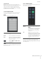
Using the PDF manual
• From the Contents on page 2, click on the desired topic to automatically jump to the corresponding page.
• Click on a link
in this manual to jump to the corresponding page.
• If you want to find information on a specific topic, function or feature, select “Find” or “Search” from the Acrobat Reader
“Edit” menu and enter a key word to locate the related information anywhere in the document.
• You can also click on desired items and topics you want to refer to in the “Bookmarks” index to the left of the main
display window, and jump to the corresponding page. (Click the “Bookmarks” tab to open the index if it is not
displayed).
NOTE
The names and positions of menu items may vary according to the version of Acrobat Reader being used.
Operation Manual
EN

MMP1 Operation Manual 2
1. Contents
2. Overview ...........................................................................................3
2-1. MMP1 Editor (for Windows/for Mac) ........................................................... 4
2-2. MMP1 Controller (for iPad).......................................................................... 4
3. Setting Up .........................................................................................5
3-1. Open the application ................................................................................... 5
3-2. Log in (MMP1 Editor only)........................................................................... 5
3-3. Select an MMP1 .......................................................................................... 5
3-4. Configure basic settings .............................................................................. 6
4. Screens .............................................................................................7
4-1. MMP1 Editor................................................................................................ 7
4-1-1. Menu bar .....................................................................................................7
4-1-2. Main screen.................................................................................................8
4-1-3. Sub screen ................................................................................................15
4-1-4. Monitor Matrix screen................................................................................18
4-1-5. Speaker Matrix screen ..............................................................................20
4-1-6. Speaker Management screen ...................................................................22
4-1-7. Patch screen .............................................................................................24
4-1-8. Settings screen..........................................................................................27
4-1-9. Information screen.....................................................................................41
4-2. MMP1 Controller ....................................................................................... 43
4-2-1. Menu bar ...................................................................................................43
4-2-2. Control view...............................................................................................43
4-2-3. Editor view - Main Monitor screen .............................................................46
4-2-4. Editor view - Ch Strip screen.....................................................................48
4-2-5. Editor view - Preference screen ................................................................51
4-2-6. Information screen.....................................................................................52
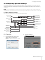
5. Configuring System Settings........................................................53
5-1. Basic settings example.............................................................................. 53
5-2. Bass Management .................................................................................... 60
5-3. Lip Sync Delay .......................................................................................... 61
5-4. Commentary functions .............................................................................. 62
6. Appendix.........................................................................................65
6-1. Error messages ......................................................................................... 65
6-2. MMP1 Editor keyboard shortcuts .............................................................. 66
7. Index................................................................................................67
Information
• The illustrations and screens as shown in this manual are for instructional purposes only.
• Yamaha Corporation makes no representations or warranties with regard to the use of the software and
documentation and cannot be held responsible for the results of the use of this manual and the software.
• Windows is a registered trademark of Microsoft® Corporation in the United States and other countries.
• Mac and iPad are trademarks of Apple Inc., registered in the U.S. and other countries.
• The company names and product names in this manual are the trademarks or registered trademarks of
their respective companies.
• Software may be revised and updated without prior notice.

2. Overview
MMP1 Operation Manual 3
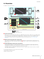
2. Overview
The MMP1 has three main functions.
Channel strip function
Allows for the use of up to eight channel strips, each equipped with HPF, LPF, EQ, compressor, insert send/return and
other functions. This can be used to input the signal from the microphone preamp to which the recording microphone is
connected and adjust sound quality when recording to produce a low-latency cue mix. The microphone on each
channel strip can also be turned on or off using a GPI, an iPad, or other similar device (see “5-4. Commentary
functions”).
Monitor processing function (max. 40x36 matrix)
This is used to select a Monitor Source, mix Monitor Sources, adjust levels, and control lip sync delay and cue mix
Talkback. You can also mix the output from channel strip () and the cue audio sent from the DAW to produce a low-
latency cue mix.
Speaker Management function (max. 32x32 matrix)
This adjusts monitor signals. The matrix input stage comes with a bass management crossover filter to allow for
unrestricted bass management not constrained by conventional 5.1 channel and 7.1 channel setups. This ensures
compatibility should new surround sound formats be introduced in the future.
The output stage comes equipped with 6-band EQ, delay and level adjustment trim controls, and can be used while
switching the output Speaker Set.
The following two applications can be used to operate the MMP1.
• MMP1 Editor (for Windows/for Mac)
• MMP1 Controller (for iPad)
FIR
IIR
Bass Management
Filter (32)
Monitor
Alignment
Process (32)
DAW
Mic Pre-amp
Surround
Speakers
Speaker
Processor
Headphone
(player)
Headphone
(engineer)
DAW
Outboard
(EQ, Compressor, etc.)
Output Patch
Output Patch
input Patch
Insert
Return
Insert Send
Channel
Strip (8)
Speaker Matrix
(32x32 Matrix Mixer)
Monitor Matrix
(40x36 Matrix Mixer)
Trim
Delay
EQ (6)
Speaker
Out
Monitor
Out
Cue Out
Headphone
Out
Channel Out

2. Overview
MMP1 Operation Manual 4
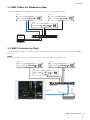
2-1. MMP1 Editor (for Windows/for Mac)
Connect the MMP1 Editor to the MMP1 on your network (one unit) to control all MMP1 functions.
2-2. MMP1 Controller (for iPad)
Connect the MMP1 Controller to the MMP1 on your network (one unit) for convenience and ease in controlling certain MMP1
functions.
NOTE
Before using the MMP1 Controller, you will need to make initial settings to your MMP1 using the MMP1 Editor.
MMP1
MMP1MMP1
MMP1
Editor
Network switch
Computer
MMP1
MMP1MMP1
iPad
Network switch
Wi-Fi access point

3. Setting Up
MMP1 Operation Manual 5
3. Setting Up
3-1. Open the application
3-1-1. MMP1 Editor
Click or double click the MMP1 icon.
3-1-2. MMP1 Controller
Tap the MMP1 Controller icon.
3-2. Log in (MMP1 Editor only)
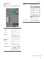
3-3. Select an MMP1
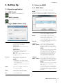
3-3-1. MMP1 Editor
Select an MMP1 on the “Select MMP1” dialog box.
NOTE
You can also display the “Select MMP1” dialog box from the
menu bar to change the desired MMP1 for operation at any time.
User Type
You can restrict the MMP1 Editor operations
according to their User Type. The following
three User Types are available.
Administrator
Allows unrestricted access to all screens
and functions.
Advanced User
Allows access to almost all functions
besides settings (Settings screen).
Basic User
Allows access only to the Main screen and
the Information screen.
Password
Enter your password to log in as an
“Administrator” or “Advanced User.”
NOTE
• “Administrator” and “Advanced User”
passwords can be set on the “Editor” tab
of the Settings screen.
• Passwords are left blank by default when
unset.
Online
Opens the “Select MMP1” dialog box for
selecting desired MMP1.
Offline
Edits the MMP1 Editor offline without
connection to or control of the MMP1.
Exit
Closes the MMP1 Editor.
NIC
Select the network interface card
connected to the MMP1 to operate.
Device
Select the MMP1 to operate. Click the
asterisk (*) in the Identify column so that the
indicator on the front panel of the
corresponding MMP1 flashes on and off.
OFFLINE
Disconnects from the MMP1 and closes the
“Select MMP1” dialog box.
CONNECT
(Editor MMP1)
Connects to the MMP1 selected in the
Device field and sends MMP1 Editor
settings to the MMP1. The “Select MMP1”
dialog box will close after settings are sent.
NOTE
You must enter the Passcode for the MMP1
when connecting to an MMP1 with a
Passcode set. You can set Passcodes on
the Information screen when logged in as
an Administrator. Entering a passcode is
not necessary when connecting to the
same MMP1 as that used previously.
CONNECT
(MMP1 Editor)
Connects to the MMP1 selected in the
Device field and loads MMP1 settings into
the MMP1 Editor. The “Select MMP1” dialog
box will close after settings are retrieved.
NOTE
You must enter the Passcode for the MMP1
when connecting to an MMP1 with a
Passcode set.
You can set Passcodes on the Information
screen when logged in as an Administrator.
Entering a passcode is not necessary when
connecting to the same MMP1 as that used
previously.

3. Setting Up
MMP1 Operation Manual 6
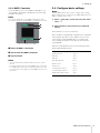
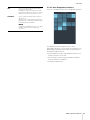
3-3-2. MMP1 Controller
Select an MMP1 on the “Select MMP1” dialog box. The
“Select MMP1” dialog box is displayed when launching
the MMP1 Controller.
NOTE
You can also display the “Select MMP1” dialog box from the
menu bar to change the desired MMP1 for operation at any time.
Select the MMP1 connection.
Tap to select the MMP1 to operate.
Tap to connect.
NOTE
• You can switch between Wireless/Wired on iOS 9.3 or later
devices.
• You must enter the Passcode for the MMP1 when connecting
to an MMP1 with a Passcode set. Entering a passcode is not
necessary when connecting to the same MMP1 as that used
previously.
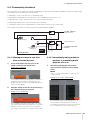
3-4. Configure basic settings
NOTE
Only the MMP1 Editor can be used to configure basic settings.
Basic settings must be configured on the MMP1 Editor before the
MMP1 Controller can be used.
1. Select “ (file icon)” on the menu bar, then select
“New.”
2. Select whether or not you want to use the Setup
Wizard.
Next, follow the on-screen instructions.
When using the Setup Wizard, configure basic settings by
answering the questions as they appear on the screen.
Canceling the Setup Wizard before it is complete will
revert settings to what they were prior to launching the
Setup Wizard.
When the Setup Wizard is not used, the following values
will be applied automatically.
Disconnecting from the MMP1
Sample Rate 48 kHz
Speaker Format Stereo
LFE Filter None
LFE Trim None
Bass Management None
Monitor Source None
Speaker Set None
Cue Mix Input Channel None
Cue Mix Output Channel None
Talkback Mic Input Channel None

4. Screens
MMP1 Operation Manual 7
4. Screens
4-1. MMP1 Editor
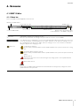
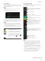
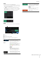
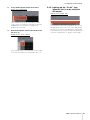
4-1-1. Menu bar
This is a shared menu that appears on all screens.
(File icon) “Administrator” privileges are required to use files.
When you open a file online, the settings in the opened file are sent to the connected MMP1.
Store different system configurations as Scenes to be loaded later depending on the studio in use or the event.
Scenes are stored from “Scene Management” in the “MISC” tab of the “Scene” tab on the Settings screen. Use
the “Confirmation Recall” option of the “Editor” tab on the Settings screen to choose whether a confirmation
dialog box appears when changing Scenes.
(Error icon) Cooling fan has stopped
Please contact your Yamaha dealer and have qualified Yamaha service personnel inspect the cooling
fan.
The backup battery voltage is reduced
Please contact your Yamaha dealer and have qualified Yamaha service personnel replace the backup
battery.
Memory defects
If the issue is still not solved even after restoring factory settings, please contact qualified Yamaha
service personnel.
Dante module defects
NOTE
Please refer to the MMP1 Getting Started for more information about restoring factory settings and contact
qualified Yamaha service personnel.
Closes the MMP1 Editor
Minimizes the MMP1 Editor
Creates and saves files
Selects a Scene
Switches screens
Displays errors
Displays online (green)/offline status
Click to display the “Select MMP1” dialog box

4. Screens
MMP1 Operation Manual 8
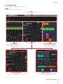
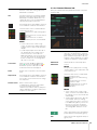
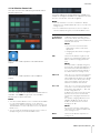
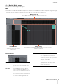
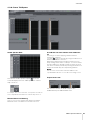
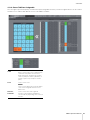
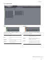
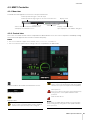
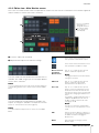
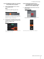
4-1-2. Main screen
This is the Main screen used for monitor control.
NOTE
This screen can be used by all User Types.
Meters
Displays Monitor Matrix Out meters
Channel strips
For setting EQ, compressor, insert, pan,
output level and other values for each
channel strip
User Assignable functions
For displaying and enabling operation
of User Assignable functions
Click the tabs to change
Selected Channel tab
For fine-tuning of the parameters for the selected
channel strip
Monitor Control tab
For selecting the audio being monitored and setting
Monitor output levels

4. Screens
MMP1 Operation Manual 9
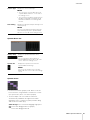
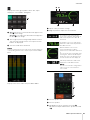
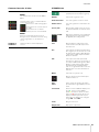
4-1-2a. Meters
Here you can display Monitor Matrix Out meters. These
channels include Monitor outputs (up to 32 ch), Downmix
L/R, and Headphone L/R.
NOTE
• The meters shown here are the same as those on the Sub
screen.
• Drag a Main Monitor Out meter to change the order.
Values less than -20 dB are displayed in green , values
less than 0 dB in yellow , and values equal to or above 0
in red . Peak hold circuits are not displayed.
NOTE
• The breakdown of Monitor outputs is based on the format
selected under “Monitor Matrix Out” in the “Monitor Matrix” tab
of the “Scene” tab on the Settings screen.
• The signal position displayed on the meters can be selected in
the “System” tab of the “Scene” tab on the Settings screen.
4-1-2b. Channel strips
For setting EQ, compressor, insert, pan, output level and
other values for each channel strip.
NOTE
• Eight channel strips are available when the MMP1’s sample
rate is 96 kHz or less, and four channel strips are available
when the MMP1’s sample rate being used is higher than
96 kHz. You can change the sample rate in the “MISC” tab of
the “Scene” tab on the Settings screen.
• Set channel strip input sources in “Channel Strip In” on the
Patch screen, and switch between these using “SOURCE A”
and “SOURCE B” on the “Selected Channel” tab on the Main
screen.
• Click to select a channel strip, and then set the parameters in
the “Selected Channel” tab on the Main screen.
• To bring up the context menu, (for Windows) right click
anywhere within the section, or (for Mac) hold down the
<control> key and then click in the section.
Click these buttons to set all Main Monitor
outputs to SOLO or MUTE.
/ Click these buttons to turn each Main Monitor
SOLO or MUTE setting on (lights up) or off.
Click these buttons to turn the oscillator on (lit)
or off. You can select the oscillator type used in
the “Oscillator” section on the Sub screen.
represents sine waves and represents pink
noise.
This is displayed when using Talkback.
Displays the signal processors applied to audio
signals in the order in which they are applied
(descending order).
Displays the EQ graph.
Displays the COMP graph.
Turns output to the PFL (Pre Fader Listen) bus on
(green) or off.
Turns output to the AFL (After Fader Listen) bus
on (green) or off.
Turns mute on (yellow) or off.
Drag, double click or use the mouse wheel to set
the pan value. To return the setting to the center,
simultaneously hold down the <Ctrl> key
(Windows) or the <command> key (Mac) and
click on the control.
Shows the status of mics controlled with the
Commentary functions.
Drag or use the mouse wheel to set output level.
To return the setting to 0 dB, simultaneously hold
down the <Ctrl> key (Windows) or the
<command> key (Mac) and click on the control.
Displays the output level.
Double click to enter a value.
Displays the channel name.
Double click to change the name.

4. Screens
MMP1 Operation Manual 10
4-1-2c. Selected Channel tab
Here you can fine-tune the parameters for the selected
channel strip.
PFL
Turn this on (green) to send outputs to Main
Monitors 1 and 2 while muting outputs from
Main Monitor 3 onwards.
AFL
Turn this on (green) to send outputs to Main
Monitors 1 and 2 while muting outputs from
Main Monitor 3 onwards. When “PFL” is on,
signals will not be sent to the Main Monitors
even when this button is turned on.
Out-of-range values entered will be corrected
to the maximum or minimum value allowed.
Shows the status of mics controlled with the
Commentary functions.
Shows the mic audio is being input.
Shows that the mic user has muted
mic audio.
Shows that the mic on and off
control by the mic user is disabled.
NOTE
• Select or deselect the “Show Cough
Status” check box of the “Editor” tab on the
Settings screen to show or hide this status
display.
• Set GPI inputs/outputs in the “GPI” tab of
the “Global” tab on the Settings screen
and use the device connected to the
MMP1 GPI [INPUT] connector to turn mics
on or off. This can also be operated using
buttons created in the “User Assignable”
tab of the “Scene” tab.
Level meter
Values less than -20 dB are displayed in
green
, values less than 0 dB in yellow ,
and values equal to or above 0 in red
.
Peak hold circuits are not displayed.
Fader
Double click on a position to move the fader
there.
Output level
Out-of-range values entered will be corrected
to the maximum or minimum value allowed.
You can also use the mouse wheel to change
the output level.
Channel name
Enter a channel name of up to
17 alphanumeric characters and symbols.
To insert a line break at any point,
simultaneously hold the <Alt> key and press
<Enter> (Windows), or hold the <option> key
and press <return> (Mac).
Channel name
Double click to change. Enter a channel
name up to 17 alphanumeric characters
and symbols. To insert a line break at any
point, simultaneously hold the <Alt> key
and press <Enter> (Windows), or hold the
<option> key and press <return> (Mac).
SOURCE A/
SOURCE B
Switches between channel strip input
sources.
NOTE
The input source (A/B) can be set using
“Channel Strip In” of the “Input Patch” tab
on the Patch screen.
Shows the status of mics controlled with
the Commentary functions.
Shows the mic audio is being
input.
Shows that the mic user has
muted mic audio.
Shows that the mic on and off
control by the mic user is
disabled.
NOTE
• Select or deselect the “Show Cough
Status” check box of the “Editor” tab on
the Settings screen to show or hide this
status display.
• Set GPI inputs/outputs in the “GPI” tab
of the “Global” tab on the Settings
screen and use the device connected
to the MMP1 GPI [INPUT] connector to
turn mics on or off. This can also be
operated using buttons created in the
“User Assignable” tab of the “Scene”
tab.
Click to switch between the signal phases
(normal phase/reversed phase (green)).
HPF
Click to turn the HPF (High Pass Filter) on
(green) or off.

4. Screens
MMP1 Operation Manual 11
HPF cutoff
frequency
Drag or use the mouse wheel to change
the HPF cutoff frequency. Double click to
enter a value. Out-of-range values
entered will be corrected to the maximum
or minimum value allowed. To return the
setting to 80 Hz, simultaneously hold
down the <Ctrl> key (Windows) or the
<command> key (Mac) and click on the
control.
LPF
Click to turn the LPF (Low Pass Filter) on
(green) or off.
LPF cutoff
frequency
Drag or use the mouse wheel to change
the LPF cutoff frequency. Double click to
enter a value. Out-of-range values
entered will be corrected to the maximum
or minimum value allowed. To return the
setting to 16 kHz, simultaneously hold
down the <Ctrl> key (Windows) or the
<command> key (Mac) and click on the
control.
INSERT
Click to turn the Insert on (green) or off.
Send Destination
Select the signal to send to the Insert.
Return Source
Select the signal to be returned from the
Insert.
(Insert) Trim
Drag or use the mouse wheel to adjust
signal levels to be sent to the Insert.
Double click to enter a value. Out-of-
range values entered will be corrected to
the maximum or minimum value allowed.
To return the setting to 0 dB,
simultaneously hold down the <Ctrl> key
(Windows) or the <command> key (Mac)
and click on the control.
SIGNAL CHAIN
Displays the signal processors applied to
audio signals in the order in which they
are applied (descending order).
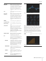
EQ
Click to turn the EQ on (green) or off.
You can choose from the following four EQ
algorithms. The color of the bar at the
bottom of the EQ graph will change based
on the algorithm selected.
PRECISE
This EQ strives for ultimate precision and
controllability. It enables you to adjust the
target point precisely, and flexibly satisfies
various requirements for sound making.
Low/High Shelving filters feature a “Q”
parameter, which enables you to adjust
the knee characteristics.
AGGRESSIVE
This EQ is musical and effective. It
enables you to add a powerful, creative
edge and serves as a powerful tool for
artistic expression.
SMOOTH
This EQ focuses on smooth sound
qualities. It contributes to a natural sound
without changing the atmosphere of the
original.
LEGACY
This is the standard EQ that has been
provided on Yamaha digital mixers since
the PM1D and PM5D.
Displays the EQ graph and filters.
Drag or use the mouse wheel to change four band EQ
parameters (Frequency, Gain, Q). Double click to enter a value.
Out-of-range values entered will be corrected to the maximum or
minimum value allowed. To return these parameters to their
default values, simultaneously hold down the <Ctrl> key
(Windows) or the <command> key (Mac) and click on the
corresponding control. Default values are F: 125 Hz/355 Hz/
3.55 kHz/6.3 kHz, G: 0 dB, and Q: 4.0 (Shelf)/1.4 (Peak)/1.0
(Notch). You can also select the EQ type from Peak and Shelf
(Shelving), or Peak and Notch.
COMP
Click to turn the compressor on (green) or
off.
Displays the COMP graph together with the GR meter and the
OUT meter.

4. Screens
MMP1 Operation Manual 12
Drag or use the mouse wheel to change compressor parameters.
Double click to enter a value. Out-of-range values entered will be
corrected to the maximum or minimum value allowed. To return
these parameters to their default values, simultaneously hold
down the <Ctrl> key (Windows) or the <command> key (Mac)
and click on the corresponding control. (shown in the table
below).
Threshold:
Ratio:
Attack:
Release:
Knee:
Input:
Output:
0.0 dB
1.00: 1
3.148 ms
290.6 ms
Soft 2
0.0 dB
0.0 dB
Trim
Drag or use the mouse wheel to adjust the
output level for the selected channel.
Double click to enter a value. Out-of-
range values entered will be corrected to
the maximum or minimum value allowed.
To return the output level to 0 dB,
simultaneously hold down the <Ctrl> key
(Windows) or the <command> key (Mac)
and click on the control.
PFL
Click to turn output to the PFL (Pre Fader
Listen) bus on (green) or off. Turn this on
to send pre fader audio signals to Main
Monitors 1 and 2 while muting outputs
from Main Monitor 3 onwards.
AFL
Click to turn output to the AFL (After Fader
Listen) bus on (green) or off. Turn this on
to send post fader audio signals to Main
Monitors 1 and 2 while muting outputs
from Main Monitor 3 onwards. When “PFL”
is on, signals will not be sent to the Main
Monitors even when this button is turned
on.
MUTE
Click to turn mute on (yellow) or off.
PAN
Drag or use the mouse wheel to set the
pan. To return pan to the center position,
simultaneously hold down the <Ctrl> key
(Windows) or the <command> key (Mac)
and click on the control.
PRE
POST
Click to change the position (pre fader/
post fader) of the signal displayed on the
meter.
Level meter
Values less than -20 dB are displayed in
green
, values less than 0 dB in
yellow
, and values equal to or above 0
in red
. Peak hold circuits are not
displayed. To change whether pre fader
or post fader values are displayed, use
the “PRE” and “POST” controls above.
Fader
Drag or use the mouse wheel to set output
levels. To return the setting to 0 dB,
simultaneously hold down the <Ctrl> key
(Windows) or the <command> key (Mac)
and click on the control.
Output level
Displays the output level. Double click to
enter a value. Out-of-range values
entered will be corrected to the maximum
or minimum value allowed. You can also
use the mouse wheel to change the
output level.

4. Screens
MMP1 Operation Manual 13
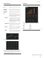
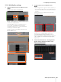
4-1-2d. Monitor Control tab
Here you can select the audio being monitored and set
Monitor output levels.
This is used to enable operation of the Main Monitor
outputs.
This is used to enable operation of the headphone
outputs.
Select the audio to be monitored from the Monitor Sources
available. Turn “SUM” on (green) to select multiple
Monitor Sources at the same time.
NOTE
• Select the format for Monitor Sources 1-8 under “Monitor Matrix
In” in the “Monitor Matrix” tab of the “Scene” tab on the
Settings screen, and then assign input sources for each in the
“Monitor Matrix In” section on the Patch screen or the Monitor
Matrix screen.
• You can confirm the destination of Monitor Sources sent to on
(displayed in green) on the Monitor Matrix screen.
Select the audio to be monitored from the available Cue
outputs. To change the available Cue outputs for selection
to Cue 5 - Cue 8, turn “Cue 5-8” on (green).
NOTE
• Select the format for Cue Sources 1-8 under the “Monitor
Matrix Out” in the “Monitor Matrix” tab of the “Scene” tab on the
Settings screen.
• You can confirm that the input source to the Cue outputs is
turned on (displayed in green) on the Monitor Matrix screen.
Monitor Level
or Headphone
Monitor Level
Click “ ” or “ ,” or use the mouse wheel to
set Monitor output level. Double click to
enter a value directly. Out-of-range values
entered will be corrected to the maximum or
minimum value allowed.
NOTE
• You can use the mouse wheel while
holding down <Shift> to make minor
adjustments.
• Changing this value will also change the
SPL value.
DIM
Click to turn the dimmer on (green) or off.
Turn this on to lower Monitor output for the
DIM Level without changing the Monitor
Level.
NOTE
This button will be on (displayed in green)
and cannot be changed while talkback is on
when “Dim main monitor while talkback is
on” is checked (in the General settings of
the “Global” tab on the Settings screen).
DIM Level
Click “ ” or “ ,” or use the mouse wheel to
set the attenuation amount of the Monitor
output signal when the dimmer is on. Double
click to enter a value directly. Out-of-range
values entered will be corrected to the
maximum or minimum value allowed.
SPL Level
Click “ ” or “ ,” or use the mouse wheel to
set the SPL to enter a value directly. Out-of-
range values entered will be “--.- dB,” and
the SPL setting will be off.
As Monitor Level values are tied to the SPL
when the SPL is set, the SPL value will
change when changing the Monitor Level
value.
For example, changing a Monitor Level of
-10 dB to -20 dB when an SPL value of
85 dB is set will result in the SPL value
changing to 75 dB.
NOTE
The SPL level cannot be changed when
“SPL Level Lock” is ON (in the “Editor” tab
on the Settings screen).
MUTE
Click to turn the Monitor output mute on
(orange) or off.

4. Screens
MMP1 Operation Manual 14
4-1-2e. User Assignable functions
Here you can display and use User Assignable functions.
This displays functions registered in the “User
Assignable” tab of the “Scene” tab on the Settings screen.
Depending on the particular functions registered, these
may appear and function as:
• An on/off button (an latch type button that switches on
and off each time you click it)
• A push button (a momentary type button that works
while the button is held down)
• A display indication only
REF
Click to change the Monitor Level value to
the reference level value.
Holding this down for at least two seconds
(until the indicator flashes) stores the current
Monitor Level value as the reference level.
DOWNMIX
Click to turn the Downmix audio output on
(green) or off.
Turn this on to send Downmix L/R outputs to
Main Monitors 1 and 2 while muting outputs
from Main Monitor 3 onwards.
NOTE
This button is disabled when the Cue output
format is selected as the audio being
monitored.

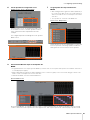
4. Screens
MMP1 Operation Manual 15
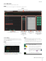
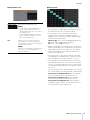
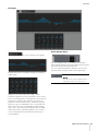
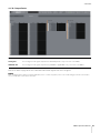
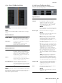
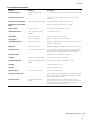
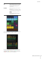
4-1-3. Sub screen
This is the Sub screen used for monitor control.
NOTE
You can use this screen when logged in as an “Administrator” or “Advanced User.”
4-1-3a. Meters
Here you can display Monitor Matrix Out meters. These
channels include Monitor outputs (up to 32 ch), Downmix
L/R, and Headphone L/R.
NOTE
• The meters shown here are the same as those on the Main
screen.
• Drag a Main Monitor Out meter to change the order.
Values less than -20 dB are displayed in green , values
less than 0 dB in yellow , and values equal to or above 0
in red . Peak hold circuits are not displayed.
NOTE
• The breakdown of Monitor outputs is based on the format
selected under “Monitor Matrix Out” in the “Monitor Matrix” tab
of the “Scene” tab on the Settings screen.
• The signal position displayed on the meters can be selected in
the “System” tab of the “Scene” tab on the Settings screen.
Meters
Displays Monitor Matrix Out meters
Monitor section
For adjusting input source and Send levels
Oscillator section
For selecting signals
to output from the
oscillator, and
adjusting their output
levels
Snapshot section
For storing and recalling
Snapshots
Talkback section
For selecting Talkback
interrupt destinations
and adjusting Talkback
output levels
Click these buttons to set all Main Monitor
outputs to SOLO or MUTE.
/ Click these buttons to turn each Main Monitor
SOLO or MUTE setting on (lights up) or off.
Click these buttons to turn the oscillator on (lit)
or off. You can select the oscillator type used in
the “Oscillator” section on the Sub screen.
represents sine waves and represents pink
noise.
This is displayed when using Talkback.

4. Screens
MMP1 Operation Manual 16
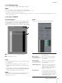
4-1-3b. Monitor section
Here you can adjust the input source and Send levels.
NOTE
Control the sources and outputs of the format selected in the
“Monitor Matrix” tab of the “Scene” tab on the Settings screen.
4-1-3c. Oscillator section
Here you can select signals to output from the oscillator,
and adjust their output levels.
NOTE
Click the or of the meter to turn the oscillator on or off.
Monitor Source
Trim
Drag or use the mouse wheel to adjust
Monitor Source levels. Double click to enter
a value. Out-of-range values entered will be
corrected to the maximum or minimum
value allowed. To return the setting to 0 dB,
simultaneously hold down the <Ctrl> key
(Windows) or the <command> key (Mac)
and click on the control.
Cue Source Trim
Drag or use the mouse wheel to adjust Cue
Source levels. Double click to enter a value.
Out-of-range values entered will be
corrected to the maximum or minimum
value allowed. To return the setting to 0 dB,
simultaneously hold down the <Ctrl> key
(Windows) or the <command> key (Mac)
and click on the control.
Cue Output Trim
Drag or use the mouse wheel to adjust Cue
output levels. Double click to enter a value.
Out-of-range values entered will be
corrected to the maximum or minimum
value allowed. To return the setting to 0 dB,
simultaneously hold down the <Ctrl> key
(Windows) or the <command> key (Mac)
and click on the control. Click “MUTE” to
mute.
Studio Speaker
Output Trim
Drag or use the mouse wheel to adjusts
studio speaker output levels. Double click
to enter a value. Out-of-range values
entered will be corrected to the maximum or
minimum value allowed. To return the
setting to 0 dB, simultaneously hold down
the <Ctrl> key (Windows) or the
<command> key (Mac) and click on the
control. Click “MUTE” to mute.
Lip Sync Delay
Drag or use the mouse wheel to set the lip
sync delay. Double click to enter a value.
Out-of-range values entered will be
corrected to the maximum or minimum
value allowed. To return the setting to 0 ms,
simultaneously hold down the <Ctrl> key
(Windows) or the <command> key (Mac)
and click on the control.
LFE Trim
Click to turn the LFE Trim on (green) or off.
Turn this on to add an LFE Trim Level to all
channels where the CH Type has been set
to “LFE” in the “Speaker Matrix” tab of the
“Scene” tab on the Settings screen.
NOTE
• You can set the CH Type in the “Speaker
Matrix” tab of the “Scene” tab on the
Settings screen.
• You can set the LFE Trim Level in the
“MISC” tab of the “Scene” tab on the
Settings screen.
LFE Filter
Click to turn the LFE Filter on (green) or off.
Turn this off to change the crossover filter
for LFE channels in the following ways.
FIR THRU
IIR (Bypass)
THRU THRU (Unchanged)
NOTE
Note that while filters will not be applied
when the crossover filter is set to “THRU,”
the same delay as that applied to the main
channel will be added.

4. Screens
MMP1 Operation Manual 17
Oscillator Trim
Drag or use the mouse wheel to set Oscillator levels.
Double click to enter a value. Out-of-range values entered
will be corrected to the maximum or minimum value
allowed. To return the setting to -20 dB, simultaneously
hold down the <Ctrl> key (Windows) or the <command>
key (Mac) and click on the control.
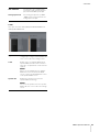
4-1-3d. Snapshot section
Here you can store parameters at a set point in time as
Snapshots to be loaded later as desired or needed.
NOTE
Up to 20 Snapshots can be stored per Scene.
NOTE
To bring up the context menu, (for Windows) right click anywhere
within the section, or (for Mac) hold down the <control> key and
then click in the section.
4-1-3e. Talkback section
Here you can select Talkback interrupt destinations and
adjust Talkback output levels.
NOTE
You can set the amount that the audio output of interrupt
destination is reduced (dimmed) when Talkback is turned on by
using “Talkback Dim Level” in the “MISC” tab of the “Scene” tab
on the Settings screen.
Store
Click to store a Snapshot at the selected
location.
Recall
Click to recall (load) the selected Snapshot.
Name
Click to select a Snapshot (or an empty field).
Double click to change the name entered.
Enter a channel name up to 17 alphanumeric
characters and symbols.
Click to lock or unlock a Snapshot.
Locked Snapshots cannot be overwritten by
selecting Store.
Talkback
Click to turn the Talkback on (green) or off.
NOTE
Set Talkback inputs and interrupt destinations
in the “Talkback Mic In” of the “Input Patch”
tab on the “Patch” screen and “Talkback
Destination” tab of the “Scene” tab on the
Settings screen.
Trim
Drag or use the mouse wheel to adjust
Talkback levels. Double click to enter a value.
Out-of-range values entered will be corrected
to the maximum or minimum value allowed.
To return the setting to 0 dB, simultaneously
hold down the <Ctrl> key (Windows) or the
<command> key (Mac) and click on the
control.

4. Screens
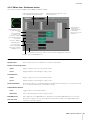
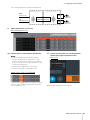
MMP1 Operation Manual 18
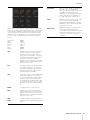
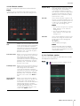
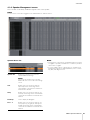
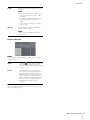
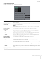
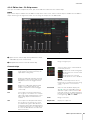
4-1-4. Monitor Matrix screen
This screen is used for routing monitor signals.
NOTE
• You can use this screen when logged in as an “Administrator” or “Advanced User.”
• This matrix is set to 40x36 when the MMP1’s sample rate is 96 kHz or less, and 20x20 when the MMP1’s sample rate being used is higher
than 96 kHz. You can change the sample rate in the “MISC” tab of the “Scene” tab on the Settings screen.
Monitor Matrix In
Monitor Matrix Out
Monitor Matrix Out names appear here. Adjust output levels here
Monitor Matrix In
For selecting input sources, and
adjusting the levels of the selected
input sources
Monitor matrix
For turning the Send output from Monitor Matrix In to Out on (green) or off,
and setting Send levels
Source
For selecting monitor matrix input sources.
NOTE
The same items can be configured on the
“Input Patch” tab on the Patch screen.
Type & No
The Monitor Matrix In input type. Monitor
Sources 1-8 will appear as Monitor 1-8, Cue
Sources 1-8 as Cue 1-8, and other inputs will
be “---” and blank.
NOTE
You can select the format for Monitor 1-8 and
Cue 1-8 in the “Monitor Matrix” tab of the
“Scene” tab on the Settings screen.
Source Label
If the Type is “Monitor” or “Cue,” double click
to add a name (label). Enter a channel name
up to 17 alphanumeric characters and
symbols. To insert a line break at any point,
simultaneously hold the <Alt> key and press
<Enter> (Windows), or hold the <option> key
and press <return> (Mac).
Trim
Double click or use the mouse wheel to
adjust input levels. Out-of-range values
entered will be corrected to the maximum or
minimum value allowed.

4. Screens
MMP1 Operation Manual 19
Monitor Matrix Out Monitor matrix
• Click to turn Send on (green) or off. When a cell has
been turned on, a signal will be sent from the cell row
(the input source) to the cell column (output).
• To turn multiple cells on or off at the same time,
simultaneously hold down the right mouse button
(Windows) or the <control> key (Mac) and then drag
and release the button (key).
Quick Assign:
Criss cross from dragging origin point
On:
Turns entire dragged area on (green)
Off:
Turns entire dragged area off
• Right click (Windows), or hold down the <control> key
and then click (Mac) on a cell that has been turned on
(appearing in green) to set Send levels. Out-of-range
values entered will be corrected to the maximum or
minimum value allowed.
• If the input source is the channel strip (Ch 1-8), right
click (Windows), or hold down the <control> key and
then click (Mac) to select either “Mono,” “L,” or “R.”
• If the Monitor Source format has been selected in the
“Monitor Matrix” tab of the “Scene” tab on the Settings
screen, you cannot set Monitor Sources 1-8 to send to
the Main Monitor, Downmix L/R, or Headphone L/R on
this screen.
Use the “Monitor Control” tab on the Main screen to turn
these Send signals on or off (described in detail below).
Send signals to the Main Monitor: Use the “Monitor
Source” selection button to turn Send on or off.
Send signals to Downmix L/R: Use the “Monitor
Source” selection button to turn Send on or off.
Send signals to Headphone L/R: Set the target to
headphone output, and then use the “Monitor Source”
selection button to turn Send on or off.
Name (Label)
Displays Monitor Matrix Out names.
NOTE
• The breakdown of Monitor Matrix Out is
based on the format selected in the
“Monitor Matrix” tab of the “Scene” tab on
the Settings screen.
• You can add Monitor Matrix Out names
(labels) in the “MISC” tab of the “Scene”
tab on the Settings screen.
Trim
Double click or use the mouse wheel to
adjust output levels. Out-of-range values
entered will be corrected to the maximum or
minimum value allowed.
NOTE
When the Cue and Studio Speaker format is
set to stereo, the same settings will be
applied to both L/R.

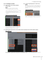
4. Screens
MMP1 Operation Manual 20
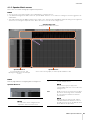
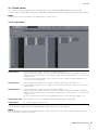
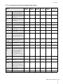
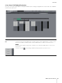
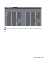
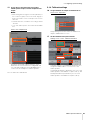
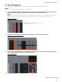
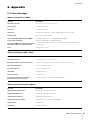
4-1-5. Speaker Matrix screen
This screen is used for routing input signals and speakers.
NOTE
• You can use this screen when logged in as an “Administrator” or “Advanced User.”
• Cells with black backgrounds can be used in the “Speaker Matrix” tab of the “Scene” tab on the Settings screen when logged in as an
Administrator.
• This matrix is 32x32 when the MMP1's sample rate is 96 kHz or less, and 16x16 when the MMP1's sample rate being used is higher than
96 kHz. You can change the sample rate in the “MISC” tab of the “Scene” tab on the Settings screen.
NOTE
Refer to page 60 when configuring bass management.
Speaker Matrix In
Speaker Matrix Out
Displays Speaker Matrix Out names
Speaker Matrix In
For selecting input sources, and
adjusting the levels of the selected input
sources
Speaker matrix
Click to turn Send on (purple) or off from Speaker Matrix In to Out
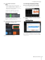
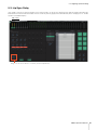
Source
For selecting speaker matrix input sources.
NOTE
The same items can be configured on the
“Input Patch” tab on the Patch screen.
Type
The input type to the speaker matrix (“Monitor”
or “LFE”) will appear here.
NOTE
You can set the Type (CH Type) in the
“Speaker Matrix” tab of the “Scene” tab on the
Settings screen.
Trim
Double click or use the mouse wheel to adjust
input levels. Out-of-range values entered will
be corrected to the maximum or minimum
value allowed.
NOTE
When the Type (CH Type) is “LFE,” and the
“LFE Trim” button in the “Monitor” section on
the Sub screen is set to on, the LFE Trim Level
will be added to the input value.
La pagina si sta caricando...
La pagina si sta caricando...
La pagina si sta caricando...
La pagina si sta caricando...
La pagina si sta caricando...
La pagina si sta caricando...
La pagina si sta caricando...
La pagina si sta caricando...
La pagina si sta caricando...
La pagina si sta caricando...
La pagina si sta caricando...
La pagina si sta caricando...
La pagina si sta caricando...
La pagina si sta caricando...
La pagina si sta caricando...
La pagina si sta caricando...
La pagina si sta caricando...
La pagina si sta caricando...
La pagina si sta caricando...
La pagina si sta caricando...
La pagina si sta caricando...
La pagina si sta caricando...
La pagina si sta caricando...
La pagina si sta caricando...
La pagina si sta caricando...
La pagina si sta caricando...
La pagina si sta caricando...
La pagina si sta caricando...
La pagina si sta caricando...
La pagina si sta caricando...
La pagina si sta caricando...
La pagina si sta caricando...
La pagina si sta caricando...
La pagina si sta caricando...
La pagina si sta caricando...
La pagina si sta caricando...
La pagina si sta caricando...
La pagina si sta caricando...
La pagina si sta caricando...
La pagina si sta caricando...
La pagina si sta caricando...
La pagina si sta caricando...
La pagina si sta caricando...
La pagina si sta caricando...
La pagina si sta caricando...
La pagina si sta caricando...
La pagina si sta caricando...
La pagina si sta caricando...
-
 1
1
-
 2
2
-
 3
3
-
 4
4
-
 5
5
-
 6
6
-
 7
7
-
 8
8
-
 9
9
-
 10
10
-
 11
11
-
 12
12
-
 13
13
-
 14
14
-
 15
15
-
 16
16
-
 17
17
-
 18
18
-
 19
19
-
 20
20
-
 21
21
-
 22
22
-
 23
23
-
 24
24
-
 25
25
-
 26
26
-
 27
27
-
 28
28
-
 29
29
-
 30
30
-
 31
31
-
 32
32
-
 33
33
-
 34
34
-
 35
35
-
 36
36
-
 37
37
-
 38
38
-
 39
39
-
 40
40
-
 41
41
-
 42
42
-
 43
43
-
 44
44
-
 45
45
-
 46
46
-
 47
47
-
 48
48
-
 49
49
-
 50
50
-
 51
51
-
 52
52
-
 53
53
-
 54
54
-
 55
55
-
 56
56
-
 57
57
-
 58
58
-
 59
59
-
 60
60
-
 61
61
-
 62
62
-
 63
63
-
 64
64
-
 65
65
-
 66
66
-
 67
67
-
 68
68


in altre lingue
- English: Yamaha MMP1 User manual
- français: Yamaha MMP1 Manuel utilisateur
- español: Yamaha MMP1 Manual de usuario
- Deutsch: Yamaha MMP1 Benutzerhandbuch
- Nederlands: Yamaha MMP1 Handleiding
- português: Yamaha MMP1 Manual do usuário
- dansk: Yamaha MMP1 Brugermanual
- čeština: Yamaha MMP1 Uživatelský manuál
- polski: Yamaha MMP1 Instrukcja obsługi
- svenska: Yamaha MMP1 Användarmanual
- Türkçe: Yamaha MMP1 Kullanım kılavuzu
- suomi: Yamaha MMP1 Ohjekirja
- română: Yamaha MMP1 Manual de utilizare
Documenti correlati
-
Yamaha MMP1 Getting Started
-
-
Yamaha NUAGE I/O (16D/16A/8A8D) Manuale del proprietario
-
-
-
-
-
-
Yamaha V3 Manuale del proprietario
-