
LIBRETTO ISTRUZIONI
PIANI COTTURA AD INCASSO
MANUEL D
INSTRUCTIONS
PLANS DE CUISSON À ENCASTRER
HANDLEIDING
INBOUWKOOKPLATEN
GEBRAUCHSANLEITUNG
EINBAUKOCHMULDEN
INSTRUCTION BOOKLET
BUILT-IN COOKTOPS
MANUAL DE INSTRUÇÕES
PLACAS DE COZINHA DE ENCASTRE
INSTRUKCJA OBS
UGI
P
YTY GAZOWE DO ZABUDOWY
HASZNÁLATI ÚTMUTATÓ
BEÉPÍTHET
ZHELYEK
NÁVOD K POU
ITÍ
VESTAVNÉ VARNÉ DESKY - SAMOSTATNÉ
CZ
IT
FR
NL
GR
HU
PL
PT
DE
GB
HGT 765 XGH


PIANI COTTURA INCASSO
IT

Avvertenze e consigli importanti per l
uso
IMPORTANTE! Questo manuale costituisce parte integrante dell
apparecchio.
Occorre conservarlo integro e a portata di mano per tutto il ciclo di vita del piano di cottura.
Consigliamo un
attenta lettura di quest
o manuale e di tutte le indicazioni in esso contenute prima
dell
utilizzo dell
apparecchio. Conservare gli eventuali ricambi in dotazione. L
installazione dovrà
essere eseguita da personale qualificato e nel rispetto delle norme vigenti. Quest
apparecchio è
previsto per un impiego domestico ed è costruito per svolgere la seguente funzione: cottura e
riscaldamento dei cibi. Ogni altro uso va considerato improprio.
Il costruttore declina ogni responsabilità per cattiva installazione, manomissione,
imperizia d
uso e per utilizzi diversi da quelli indicati.
Verificare che il prodotto non abbia subito danni durante il trasporto.
Gli elementi dell
imballo (sacchetti di plastica, polistirolo espanso, nylon, ecc.) non devono
essere lasciati alla portata dei bambini,
in quanto potenziali fonti di pericolo.
L
imballo è costituito da materiale riciclabile ed è contrassegnato dal simbolo
Non disperdere nell
ambiente.
Quest
o apparecchio non è destinato ad essere usato da bambini e persone incapaci o inesper
te
all
uso del prodotto, a meno che non vengano sorvegliate o istruite riguardo all
uso
dell
apparecchio da una persona responsabile
della loro sicurezza.
S
orvegliare
i
bambini
in modo tale da assicurarsi che non giochino con l
apparecchio
L
installazione e t
utti i collegamenti gas/elettrici devono essere eseguiti da personale.
qualificato, nel pieno rispetto delle norme di sicurezza e delle leggi vigenti, sulla base delle
indicazioni fornite dal costruttore.
La sicurezza elettrica è assicurata solo quando il
prodotto è collegato ad un efficiente
impianto di messa a terra.
E
rischioso modificare o tentare di modificare l
apparecchio. In caso di guasto non tentare di
riparare da soli l
apparecchio ma richiedete l
assistenza di un tecnico qualificato.
Dopo aver
utilizzato il piano, assicurarsi che l
indice delle manopole sia in posizione di
chiusura e chiudere il rubinetto principale del condotto d
erogazione del gas o il rubinetto della
bombola.
Qualora decidesse di non utilizzare più quest
apparecchio, prima di
gettarlo al macero,
si raccomanda di renderlo inoperante nel modo previsto dalle leggi vigenti in materia di salute e
tutela dell
ambiente, rendendo innocue le parti che possono costituire elemento di pericolo per i
bambini.
La targa d
identificazione, co
n i dati tecnici, si trova visibilmente posizionata sotto il carter ed
allegata a questo manuale. La targhetta sotto il carter non deve mai essere rimossa.
Le illustrazioni per l
utilizzo dell
apparecchio sono raggruppate nella parte finale del
presente ma
nuale.
Dichiarazione di conformità
Questo apparecchio è conforme alle seguenti direttive CE:
- 90/396/CEE
Apparecchi a gas
- 2006/95/CEE
Bassa tensione
- 2004/108/CEE
Compatibilità elettromagnetica
- 89/109/CEE
Materiali od oggetti che possono venire a contatto di generi alimentari
-
Regolamento CE n° 1935/2004: idoneità dei materiali al contatto con i cibi
Queste istruzioni sono valide solamente per i paesi di
destinazione i cui simboli d
identificazione figurano sulla
targhetta posta nel libret
to istruzioni e sull
apparecchio


CARATTERISTICHE DEL PIANO
Avvertenze:
Questo apparecchio è del tipo previsto per essere incassato sui mobili.
La classe d’installazione è di tipo 3 per la parte gas e di tipo Y per la parte elettrica.
I mobili devono essere resistenti alla temperatura fino ad almeno 90°C.
Per una più corretta installazione vedere il paragrafo relativo e i disegni di riferimento.
L’utilizzo di un apparecchio di cottura a gas comporta la produzione di calore ed umidità nel
locale in cui è installato. Fare in modo che la cucina sia bene areata: tenere aperti gli orifizi
di areazione naturale, o installare un dispositivo d’areazione meccanica (cappa di
ventilazione). Un utilizzo intensivo e prolungato dell’apparecchio può richiedere
un’areazione supplementare, ad esempio aprendo una finestra, o un areazione più
efficace, come per esempio aumentando la velocità della cappa.
Questo libretto è stato previsto per un solo tipo di piano. Dalla targhetta dati che si trova sul retro, Lei
può verificare le corrispondenze del modello. Con queste indicazioni, ed i dati contenuti nei seguenti
paragrafi, guardando la figura posta alla fine del manuale (Fig 1), potrà sapere com’è
composto il suo apparecchio.
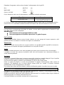
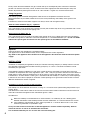
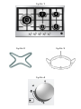
PUNTI DI COTTURA
Mod: HGT 765
(Fig. 1)
1. Bruciatore triplacorona 3,8 sinistro
(TR)
2. Bruciatore posteriore centrale rapido (R)
3. Bruciatore anteriore centrale ausiliario (A)
4. Bruciatore semi-rapido posteriore destro
(SR)
5. Bruciatore semi-rapido anteriore destro (SR)

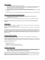
USO DEL PIANO DI COTTURA
BRUCIATORI A GAS
L
afflusso del gas ai bruciatori è regolato dalle manopole di fig. 4 che comandano i rubinetti.
Facendo coincidere l
indice con i simboli serigrafati si ottengono le seguenti regolazioni:
Rubinetto chi
uso, nessuna erogazione di gas
Portata massima, massima erogazione di gas
Portata minima, minima erogazione di gas
Accensione dei bruciatori
Questi modelli sono dotati di valvola di sicurezza che, qualora il bruciatore dovesse spegnersi p
er
qualsiasi motivo, interromperà automaticamente l
erogazione del gas.
Per ripristinare il funzionamento, riportare la manopola in posizione e ripetere le operazioni di
accensione illustrate nei prossimi paragrafi.
Uso dei bruciatori dotati di
rubinetto con sicurezza
P
rocedere come segue:
Nei modelli provvisti di accensione incorporata nella manopola ruotare la manopola del rubinetto
gas fino alla posizione di massima erogazione, quin
di premere e mantenere la pressione per
circa 4÷5 secondi. Rilasciare la manopola e regolare la fiamma ruotando la manopola sino a
raggiungere l
intensità
desiderata.
Avvertenza
:
Il dispositivo di accensione non può essere azionato
per più di 15
.
Se dopo tale periodo il bruciatore non si è ancora acceso, o se si è spento per cause
accidentali, aspettare 1minuto prima di ripetere l
operazione.
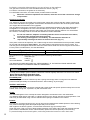
Uso delle griglie
Le griglie del piano di cottura sono state progettate
per rendere agevole e sicuro l
utilizzo del prodotto.
Consigliamo di verificare, prima d
ogni utilizzo, l
esatto posizionamento e la loro stabilita sul piano.
Inoltre, verificare che i gommini d
appoggio siano sempre integri e sistemati correttamente.
Gri
glia per piccoli recipienti
(Fig. 2
)
-
Optional
Si appoggia solo sopra la griglia del bruciatore ausiliario (il più piccolo) quando si impiegano recipienti
di piccolo diametro per evitare il loro rovesciamento.
Griglia speciale per pentole
WOK
(Fig. 3)
Si appo
ggia solo sopra la griglia del tripla
-corona quando si impiegano recipienti
WOK
(a fondo
concavo).
Si raccomanda, per non causare gravi anomalie di funzionamento
del
bruciatore, di
non
utilizzare le pentole wok senza questa speciale griglia e di non uti
lizzarla per pentole a fondo
piatto.
Scelta del bruciatore
La simbologia stampigliata sul cruscotto (disegno fig.4) a lato delle manopole indica la
corrispondenza fra manopola e bruciatore. La scelta del bruciatore più adatto dipende dal diametro e
dalla capacità dei recipienti (vedi tabella). E
importante che il diametro della pentola sia adeguato
alla potenza del bruciatore, per non comprometterne il rendimento.
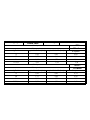
Diametro pentole
Bruciatore
Diametro minimo
Diametro massimo
Ausiliario
60 mm (con riduzione)
140 mm
Semirapidi
160 mm
200 mm
Rapido
200 mm
240 mm
Triplacorona
240 mm
260 mm

ADATTAMENTO AI DIV
ERSI TIPI DI GAS
Qualora dovesse rendersi necessario l
adattamento del piano ad un gas diverso da quello per cui è
predisposto, si devono sostituire gli iniettori.
Nel caso in cui gli iniettori di ricambio non siano forniti a corredo, sono reperibili pre
sso i Centri Assistenza.
La scelta degli iniettori da sostituire dovrà essere fatta secondo le tabelle iniettori poste a fine del libretto.
Gli iniettori sono identificabili con il diametro, espresso in centesimi di mm stampigliato sul corpo degli iniettor
i
stessi.
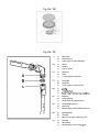
Sostituzione degli iniettori
Togliere le griglie e lo spartifiamma dal piano
Con una chiave fissa sostituire gli iniettori
J
(fig.10) con quelli idonei per il gas da utilizzare.
Rimontare i bruciatori.
I bruciatori non richiedono la regolazi
one dell
aria primaria.
Regolazione del minimo
Dopo avere sostituito gli iniettori, accendere il bruciatore e sfilare la manopola. Portare il rubinetto
nella posizione di minimo, inserire un cacciavite all
interno dell
asta: avvitare per diminuire la fia
mma,
svitare per aumentarla. (fig. 10)
Per il gas G30/G31 avvitare completamente la vite di regolazione.
In ogni caso il risultato dovrà essere una piccola fiamma omogenea e regolare lungo tutta la corona
del bruciatore.
Verificare infine che, ruotando rapidamente il rubinetto dalla posizione massima a quella minima non
si abbiano spegnimenti. Nel caso di bruciatori con sicurezza, verificare che la fiamma lambisca
leggermente la termocoppia. Verificare la corretta regolazione lasciando acceso alcuni minuti il
bruciatore. Se questo si spegne aumentare il minimo.
ISTRUZIONI PER L
INSTALLAZIONE
Importante!
Le istruzioni sono rivolte ad un installatore qualificato.
L
apparecchiatura deve essere installata correttamente, in conformità alle norme in vigore.
Qualsiasi intervento deve essere eseguito con l
apparecchio elettricamente disinserito.
INSTALLAZIONE
:
L
installazione è a carico dell
acquirente. La Casa Costruttrice è esonerata da questo servizio. Gli
eventuali interventi richiesti alla Casa Costruttrice, se dipendono da un
errata installazione, non sono
compresi nella garanzia.
Nel caso di inserimento su base con forno è necessario prendere opportune precauzioni al fine di
assicurare un
installazione conforme alle norme antinfortunistiche (CEI
UNI
CIG). Si presti
particolare attenzione che il cavo elettrico ed il tubo di alimentazione gas siano posizionati in modo da
non venire a contatto con le parti calde dell
involucro del forno.
Inoltre, se sotto al piano cottura è installato un forno senza v
entilatore di raffreddamento è necessario
praticare delle aperture nel modulo da incasso per garantire una corretta circolazione dell
aria. Tali
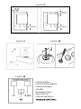
aperture devono garantire una superficie libera di almeno 300 cm2 ripartiti come mostrato nella
figura 8.

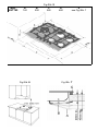
In
stallazione nel top (piano del mobile)
Il piano di cottura può essere installato in tutti i mobili, purché resistenti al calore (temperatura minima
di 90°C).
Le dimensioni del foro da praticare nel piano del mobile e le distanze minime tra le pareti poste
riori,
laterali e sovrastanti l
apparecchio sono indicate in figura 5 e 6.
Tenere presente che:
Quando il piano viene installato senza forno in accoppiamento, è tassativo l
impiego di un
pannello di separazione tra il fondo del piano ed il mobi
le sottostante, ad una distanza minima
di 10 mm.
In caso di accoppiamento piano/forno, interporre un divisorio ad una distanza minima di 15 mm
mantenendo comunque un
areazione come specificato in fig. 8.
In ogni caso l
allacciamento elettric
o dei due apparecchi deve essere realizzato
separatamente,
sia per ragioni elettriche sia per facilitarne l
estraibilità.
E
consigliato utilizzare un forno provvisto di raffreddamento interno forzato.
Fissaggio del piano
Il fissaggio
del piano di cottura al mobile deve essere effettuato come segue:
Posizionare l
apposita guarnizione sigillante fornita in dotazione lungo il perimetro esterno del
foro praticato nel mobile seguendo lo schema indicato in fig.5, in modo che le estr
emità delle
strisce siano perfettamente unite tra loro senza sormontarsi.
Sistemare il piano nel foro del mobile curandone la centratura.
Fissare il piano al mobile con le apposite staffe fornite in dotazione come illustrato in fig.7.
Una corretta installazione della guarnizione sigillante, offre un
assoluta garanzia contro le infiltrazioni
di liquidi
.
Locale di installazione e scarico dei prodotti della combustione
L
apparecchio deve essere installato e fatto funzionare in locali idonei, e com
unque in
conformità alle leggi vigenti.
L
installatore deve fare riferimento alle leggi in vigore per quanto riguarda la ventilazione e
l
evacuazione dei prodotti della combustione.
Si ricorda a tale proposito che l
aria necessaria alla combustione è di 2m3/h per ogni kW di
potenza (gas) installata.
Locale di installazione
Il locale dove è installata l
apparecchiatura a gas, deve avere un naturale afflusso d
aria necessaria
alla combustione dei gas (norme UNI
-
CIG 7129 e 7131)
L
afflusso di aria deve venire direttamente da una o più aperture praticate su una sezione libera di
almeno 100 cm2 (A)
Fig.9.
Questa apertura deve essere costruita in modo da non venire ostruita ne dall
interno ne dall
esterno e
posizionata vicino al pavimento, preferibilmente dal lato opposto all
evacuazione dei prodotti della
combustione.
Quando non è possibile praticare le necessarie aperture, l
aria necessaria può venire da un locale
adiacente, ventilato come richiesto, purché questo locale non sia una camera da letto, un ambiente
pericoloso o in depressione (UNI
-
CIG 7129).

Scarico dei prodotti della combustione
Gli apparecchi di cottura a gas devono scaricare i prodotti della combustione attraverso cappe
collegate direttamente a canne fumarie o direttamente all
ester
no (fig.9).
In caso non sia possibile installare la cappa, è necessario l
impiego di un elettroventilatore applicato
ad una parete esterna o alla finestra dell
ambiente. Questo elettroventilatore deve avere una portata
tale da garantire un ricambio d
aria
della cucina di almeno 3
-
5 volte il suo volume (UNI
-
CIG 7129).
Componenti illustrati in fig.9:
A
: Apertura per entrata aria
C
: Cappa per evacuazione prodotti della combustione
E:
Elettroventilatore per evacuazione prodotti della combustione
Allacciament
o all
impianto gas
Prima dell
installazione assicurarsi che le condizioni di distribuzione locale (natura e
pressione del gas) e le regolazioni del piano siano compatibili. Per fare questo verificare i
dati della targhetta prodotto appli
cata sul piano e su questo libretto.
Il collegamento gas deve essere eseguito in conformità alle norme UNI-CIG 7129 e 7131. Il piano di
cottura deve essere collegato all
impianto gas utilizzando tubi metallici rigidi o tubi flessibili in acciaio
inox a pa
rete continua, conformi alla norma UNI
-
CIG 9891 con estensione massima di 2 m.
Assicurasi che nel caso di utilizzo di tubi metallici flessibili, questi non vengano a contatto con parti
mobili o schiacciati.
Eseguire il collegamento in modo da non provocare
sollecitazioni di alcun genere sull
apparecchio.
Il raccordo di entrata del gas è filettato G½
conico. (Fig.13)
Per collegamenti ISO R7 non è necessario interporre la guarnizione.
Per collegamenti ISO R228 è necessario interporre la rondella di testa dat
a in dotazione.
Dopo le operazioni di allacciamento, verificare la tenuta delle connessioni con una
soluzione saponosa.
Collegamento elettrico
L
apparecchio deve essere allacciato alla rete elettrica verificando che la tensione corrisponda al
valore indicato nella targhetta caratteristiche e che la sezione dei cavi dell
impianto elettrico possa
sopportare il carico indicato anch
esso nella targhetta.
La spina che viene utilizzata per la connessione deve essere a norma, idonea alla potenza assor
bita
dall
apparecchio.
Qualora si collegasse l
apparecchio direttamente alla rete, è necessario interporre tra l
apparecchio e
la rete un interruttore onnipolare con apertura minima tra i contatti di 3 mm, dimensionato per il carico
e rispondente alle norm
ative in materia.
Non utilizzare riduzioni, adattatori o deviatori per l
allacciamento alla rete, in quanto
potrebbero surriscaldarsi e provocare bruciature.
La messa a terra dell
apparecchio è obbligatoria. Il costruttore declina ogni responsabil
ità
derivante dalla mancata osservanza di tale norma. (Fig.11)
In caso di sostituzione del cavo di alimentazione, utilizzare un cavo avente le stesse caratteristiche di
quello fornito, adatti al carico ed alla temperatura (tipo T90°C) e deve essere richiesto al centro
assistenza. E
inoltre necessario che l
estremità che va all
apparecchio abbia il filo di terra Giallo-
Verde più lungo di 20 mm rispetto agli altri.

Rispettare il seguente codice
-
colore durante il collegamento dei singoli fili
:
BLU
NEUTRO
(N)
MARRONE
FASE
(L)
GIALLO
-
VERDE
TERRA
Per la dimensione del cavo di alimentazione, consultare la tabella sottostante:
Tipo di piano
Dimensione
Con bruciatori a gas
3 X 0,75 mm
2
H05 V2V2
-F
IL COSTRUTTORE DECLINA OGNI RESP
ONSABILITA NEL CASO CHE LE ISTRUZIONI SOPRA
RIPORTATE E LE NORMALI NORME ANTINFORTUNISTICHE NON VENGANO RISPETTATE.
PULIZIA
Per una buona conservazione del piano di cottura, occorre pulirlo regolarmente al termine di ogni
uso, dopo averlo lasciato raf
freddare.
IMPORTA
NTE:
Non rimuovere mai le manopole dalla loro sede.
N
on
usare
a
pparec
c
hi di pulizia a pressione o a getto di vapore
Parti smaltate
Tutte le parti smaltate devono essere lavate soltanto con una spugna ed acqua saponata o altri
prodotti specifici non abrasivi. Al termine asciugare accuratamente.
Pianale inox
Il
pianale in acciaio inox va pulito con un panno umido e con prodotti specifici reperibili in commercio.
Dopo averlo risciacquato asciugare possibilmente con una pelle di daino.
Griglie
Le griglie smaltate del piano sono stata progettate per poter essere l
avate anche in lavastoviglie.
Le griglie in acciaio inox possono assumere nella zona dei bruciatori una colorazione bluastra, a
causa della temperatura.
Bruciatori
I bruciatori, composti di due pezzi, possono essere tolti e lavati con prodotti adeguati. Dopo la pulizia
si deve asciugare in modo accurato e rimessi perfettamente nella loro sede.
P
er
l accensione elettrica, verificare che l elettrodo E (fig.12) sia sempre pulito.
Pulire la sonda T (fig.12) in modo da permettere il regolare funzionamento della valvola di
sicurezza. Sia l elettrodo che la sonda devono essere puliti con cautela. Al termine rimettere
perfettamente nel loro alloggiamento i bruciatori.
Per evitare danni all accensione elettrica, evi
tare di utilizzarla quando i bruciatori non sono in sede.
MANUTENZIONE
Gli apparecchi non hanno bisogno di particolari manutenzioni, tuttavia si raccomanda di voler fare
eseguire un controllo almeno una volta ogni due anni.
Qualora avvenissero indurimenti nella rotazione delle manopole o si sentisse odore di gas chiudere il
rubinetto generale e chiamare l assistenza tecnica.
Il rubinetto difettoso va sostituito assieme alla sua guarnizione.


Important warnings and tips for use
IMPORTANT!
This manual constitutes an integral part of the appliance. It must be kept intact and
within easy reach during the entire life of the cooktop. Please carefully read this manual and all the
instructions contained herein before using the appliance. Keep any spare parts supplied with the
appliance. Installation must be carried out by a qualified technician and in compliance with current
regulations. This appliance is intended solely for domestic use and is designed for the following
functions:
cooking and reheating food
. Any other use is considered as improper.
The manufacturer declines all liability resulting from poor installation, tampering, inexpert
use and use for purposes other than those specifically stated
.
Check that the appliance has not been damaged during transport.
Keep all packaging materials (plastic bags, polystyrene foam, nylon, etc.) away from children, as
they are potentially dangerous.
Warning: in case of disassembly, maintenance and cleaning of the appliance, be careful, some
parts could be
sharp
.
Please use suitable prevention and protection equipment
The packaging material is recyclable, and marked with the recycling symbol
Dispose of the appliance responsibly.
This appliance is not intended for use by persons (including children) with reduced physical,
sensory or mental capabilities, or lack of experience and knowledge, unless they have been given
supervision or instruction concerning use of the appliance by a person responsible for their safet
y.
Children should be supervised to ensure that they do not play with the appliance.
Installation and gas/electrical connections must be carried out by a qualified technician in
accordance with the manufacturer's instructions and in full compliance with current laws and
safety
regulations.
Electrical safety can only be guaranteed if the product is connected to a suitable earth connection.
It is dangerous to modify or attempt to modify the appliance. In the event of a malfunction, do not
attempt to repair th
e appliance yourself, but contact a qualified technician.
After using the cooktop, ensure the indicator on the knob is turned to the "off" position and close the
mains gas delivery tap or the gas cylinder tap.
Should you decide not to use the appliance any longer, before scrapping it make it unusable in
accordance with current environmental health and safety laws, ensuring any parts which might
constitute a danger to children are rendered harmless.
The appliance data plate, with technical specifications, is positioned at a visible point under the
safety cover and is also enclosed with this manual. The data plate below the safety cover must
under no circumstances be removed.
Illustrations for the use of the appliance are grouped together at the end of this ma
nual.
Declaration of Conformity
This appliance conforms to the following EC directives:
90/396/EEC
Gas safety requirements
73/23/EEC
Low voltage
-
Replace from 2006/95/EC and modifications
89/336/EEC
Electromagnetic compatibility
-
Replaced from
2004/108/EC and modifications
89/109/EEC
Materials or objects destined to come into contact with foodstuffs
Regulation EC N°1935/2004
Materials or objects destined to come into contact with foodstuffs
These instructions are valid only for those countri
es whose ID initials appear on the
data plate found on the instructions handbook and on the appliance
3

COOKTOP CHARACTERISTICS
Warnings:
This appliance is intended to be built
-
in on furniture.
The installation class is type 3 for the gas part and type Y for the electric part.
The furniture must be resistant to temperatures up to at least 90°C.
F
or correct installation, see the relative section and the reference drawings.
The use of a gas cooking appliance leads to the production of heat and humidity in the room in which
it is installed. Make sure the kitchen is well
-
ventilated: keep the natural
airing passages open or
install a mechanical ventilation device (hood). Intensive and extended use of the appliance may
require additional airing, such as opening a window, or more efficient ventilation, such as increasing
the speed of the hood.
This hand
book is intended for a single type of cooktop. The typeplate data shown on the back allows you to
verify that it corresponds to your model.
The indications provided in the next sections, along with the figure located at the end of the manual (Fig 1),
will
help you become familiar with your appliance.
COOKING POINTS
Mod: HGT 765
(Fig. 1)
1. Left Triple
-
Crown 3,8 burner (TC)
2. Middle rear Rapid burner (R)
3. Middle front Auxiliary (A)
4. Right rear Semi
-
Rapid burner (SR)
5. Right front Semi
-
Rapid burner (SR)
USING THE COOKTOP
Gas burners
The inflow of gas to the burners is adjusted by the knobs in fig.4 that control the taps.
When the knob pointers coincide with the symbols shown below, the following settings are
obtained:
Tap closed, no gas supply
Maximum flow, maximum gas supply
Minimum flow, minimum gas supply
4

Igniting the burners
This model is equipped with a safety valve which, if the burner
goes out for any reason, automatically
interrupts the supply of gas.
To restore operation, move the knob to position
and repeat the igniting operations described in the next
section.
Using burners with safety valves
o
Turn the knob of
the gas tap to the maximum supply position, then press and hold down for about 4
-
5 seconds.
Release the knob and adjust the flame by turning the knob until reaching the desired intensity.
o Warning
:
The ignition device cannot be operated for more than 15.
If
after this period the burner still has not lit, or if it has gone out for accidental reasons, wait at least
1 minute before repeating the operation.
Burner selection
The symbol printed above each knob on the control panel (drawing in fig.4) indicates t
he correspondence
between knob and burner. The selection of the most suitable burner depends on the diameter and capacity
of the cookware (see table).
It is important that the pot diameter is suited to the power of the burner, in order to not compromise i
ts high
efficiency.
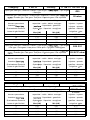
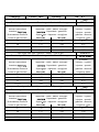
Pot / Pan diameter
Burner
Minimum diameter
Maximum diameter
Auxiliary
60 mm (with reducer)
140 mm
Semirapid front
160 mm 200 mm
Semirapid rear
160 mm 200 mm
Rapid
200 mm 240 mm
Triple
-
crown
240 mm 260 mm
Adapting to different t
ypes of gas
If it is necessary to adapt the cooktop to gas different than that for which it is designed, the injectors will have
to be replaced.
The spare injectors, if not provided with the cooktop, are available at the Service Centres.
The injectors to
be replaced should be selected according to the injectors table.
The injectors are identified by their diameter, expressed in hundredths of mm and printed on the body of the
injectors themselves.
Replacement of the injectors
Remove the grates and the flam
e spreader from the cooktop.
Use an open
-
end spanner to replace the injectors J (fig. 10) with the appropriate injectors for the gas
to be used.
Reassemble the burners.
No primary air regulation is necessary for the burners.
Adjustment of the minimum
Af
ter replacing the injectors, light the burner and take off the knob. Move the tap to the minimum position,
insert a screwdriver in the rod and adjust as follows: screw in to decrease the flame, unscrew to increase the
flame. (fig. 10)
For G30/G31 gas, scr
ew the adjustment screw in completely.
In any case, the result should be a small flame which is uniform and regular along the entire crown of the
burner.
5

Finally, check that the flame does not go out when the tap is turned quickly from maximum to minimum
position. For burners with safety valves, check that the flame slightly licks the thermocouple. Verify the
correct adjustment by leaving the burner on for a few minutes. If it goes out, increase the minimum.
Using the grates
The cooktop grates have been
designed to make the use of the product convenient and safe.
We recommend that you check, before each use, the exact positioning and stability of the grate on the
cooktop.
Furthermore, check that the rubber supports are always intact and arranged correctly
.
Grate for small cookware (Fig. 2)
-
Optional
This is placed only over the grate of the auxiliary burner (the smallest one) when using cookware with a small
diameter in order to prevent it from tipping over.
Special grate for WOKs (Fig. 3)
This is pla
ced only over the grate of the triple crown burner when using a WOK (pan with concave bottom).
To avoid causing serious anomalies in the burner operation, it is recommended that you
do not use WOKs
without this special grate and do not use the special grat
e for flat
-
bottom cookware.
INSTALLATION INSTRUCTIONS
Important!
These instructions are intended for a qualified installer.
The appliance must be installed correctly and in compliance with current regulations.
Any work on the appliance must be done wi
th the appliance disconnected from the electrical power
supply.
INSTALLATION:
Installation is completely chargeable to the buyer. The Manufacturing Company is exempt from this service.
Any operations requested from the Manufacturing Company as a result
of incorrect installation are not
covered by the guarantee.
If the cooktop is being installed on an oven base, all the necessary precautions must be taken to ensure
installation in compliance with safety regulations (CEI
-
UNI
-
CIG). Pay particular atten
tion that the electrical
cable and gas supply pipe are positioned so as to not come in contact with the hot parts of the oven casing.
Furthermore, if an oven without a cooling fan is installed under the cooktop, it is necessary to make openings
in the buil
t-
in unit to ensure proper air circulation. These openings must guarantee a free surface of at least
300 cm2 distributed as shown in figure 8.
Installation in the top (surface of the furniture)
The cooktop can be installed on all furniture, as long as i
t is heat resistant (withstanding temperatures up to
at least 90°C).
The dimensions of the hole to make on the furniture surface and the minimum distances from the back and
side walls and above the appliance are indicated in figures 5 and 6.
Consider that
:
When the cooktop is installed without an oven beneath, it is mandatory to use a dividing panel
between the bottom of the cooktop and the furniture underneath, at a minimum distance of 10 mm.
If the cooktop is matched with an oven, place a partition at a
minimum distance of 15 mm, while
maintaining ventilation as specified in fig. 8.
In any case the electrical connection of the two appliances must be realized separately, both for
electrical reasons as well as to facilitate their extraction.
It is recomme
nded that you use an oven with a forced cooling fan.
6

Fixing the cooktop
The cooktop must be fixed to the furniture as follows:
Position the appropriate sealing gasket provided with the cooktop along the external perimeter of the
hole made in the furnitur
e according to the diagram in fig. 5, so that the ends of the strips are
perfectly joined to one another without overlapping.
Arrange the cooktop in the hole on the furniture, making sure that it is centered.
Fix the cooktop to the furniture with the appro priate brackets supplied with the cooktop as illustrated
in fig. 7.
Correct installation of the sealing gasket provides an absolute guarantee against the infiltration of liquids.
Installation room and discharge of combustion products
The appliance must
be installed and operated in suitable rooms, and in any case in
compliance with current laws.
The installer must refer to current laws regarding ventilation and evacuation of the combustion products
.
In this regard, note that the air necessary for combu
stion is 2m3/h for each kW of power (gas)
installed.
Installation room
The room where the gas appliance is installed must have a natural inflow of air necessary for combustion of
the gas (standards UNI
-
CIG 7129 and 7131).
The inflow of air must come dir
ectly from one or more openings made on a free section of at least 100 cm2
(A, fig.9);
This opening must be built to ensure that it does not beco
me obstructed either internally or externally, and it
must be positioned near the floor, preferably on the side opposite the evacuation of combustion products.
When it is not possible to make the required openings, the necessary air may come from an adjace
nt room,
ventilated as required, as long as this room is not a bedroom, a hazardous environment or under vacuum
(UNI
-
CIG 7129).
Discharge of combustion products
Gas cooking appliances must discharge the combustion products through hoods connected direct
ly to
exhaust flues or directly outdoors (fig. 9).
If a hood cannot be installed, it is necessary to use an electric fan attached to an external wall or window in
the room. This electric fan must have a suitable capacity to guarantee an air renewal of the
kitchen at least
3-
5 times its volume (UNI
-
CIG 7129).
Components illustrated in fig. 9
A
: Opening for air intake
C
: Hood for evacuation of combustion products
E:
Electric fan for evacuation of combustion products
Connection to the gas system
Before
installation, make sure the local distribution conditions (type and pressure of the gas)
and the cooktop adjustments are compatible. To do this, check the data on the product
typeplate attached to the cooktop and shown in this handbook.
The gas connection
must be carried out in compliance with the standards UNI
-
CIG 7129 and 7131. The
cooktop must be connected to the gas system using metal pipes or continuous
-
wall stainless steel hoses, in
compliance with standard UNI
-
CIG 9891, with a maximum length of 2 m.
If metal hoses are being used, make sure that these do not touch any moving parts and are not crushed.
7

Perform the connection without producing any type of stress on the appliance.
The gas feed connector is a G1/2" threaded concentric reducer. (Fig.13)
For ISO R7 connections, the gasket is not necessary.
For ISO R228 connections, the head washer provided mu
st be inserted.
When the connection operations are finished, check the seal of the connections using a
soap solution.
Electrical connection
The appliance must be connected to the mains power supply after verifying that the voltage corresponds
to the val
ue indicated in the typeplate characteristics and that the sections of the electrical system cables
can support the load indicated on the typeplate.
The plug that is used for the connection must be up to standard and suitable for the power absorbed by
the
appliance. If the appliance is to be connected directly to the mains, an omnipolar switch must be
placed between the appliance and the mains which has a minimum opening distance of 3 mm between
the contacts, is suitably sized for the load and satisfies the
relative standards.
Do not use reducers, adapters or shunting switches for the connection to the mains,
since these may overheat and cause burnouts.
The earthing of the appliance is mandatory. The manufacturer declines all
responsibility resulting from
failure to observe this rule. (Fig. 11)
If the power cord must be replaced, use a cable having the same characteristics as that provided, suitable
for the load and temperature
(type T90°C
). This cable must be requested from the service centre. The
end tha
t goes to the appliance must also have the Yellow
-
Green earth wire 20 mm longer than the others.
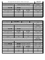
For the power cord dimensions, see the table below:
Type of cooktop
Dimension
Only with gas burners
3 X 0.75 mm2 H05 V2V2
-F
It is important connect the wire in accordance with the following colours/codes
BLUE
NEUTRAL (N)
BROWN
LIVE (L)
YELLOW
-
GREEN
EARTH
THE MANUFACTURER DECLINES ALL R
ESPONSIBILITY IF THE INSTRUCTIONS ABOVE AND
RELEVANT SAFETY STANDARDS ARE NOT OBSERVED.
CLEANING
To keep your cooktop in good condition, it should be cleaned regularly after each use once it has cooled.
Never remove the knobs from their seats.
Enamell
ed parts
All enamelled parts must be washed only with a sponge and soapy water or using other non
-
abrasive
products made specifically for enamelled surfaces. After washing, dry thoroughly.
Stainless steel surface
The stainless steel surface should be cl
eaned with a damp cloth and specific products easily found on the
market.
After rinsing well, if possible, dry with a buckskin cloth.
Grates
The enamelled grates of the cooktop have been designed to be washed even in the dishwasher.
The stainless steel r
educer may take on a bluish colouring in the burner area due to the temperature. This
effect may be attenuated using common stainless steel sponges available on the market.
Burners
The burners, composed of two pieces, can be removed and washed with suita
ble products. After cleaning,
they must be thoroughly dried and replaced precisely on their seats.
With regard to the electric ignition, check that the electrode E (fig.12) is always clean.
Clean the probe T (fig.12) so as to allow regular operation of the
safety valve. Both the electrode and the
probe must be cleaned with caution. When finished, replace the burners precisely in their housing.
To prevent damage to the electric ignition, avoid using it when the burners are not in their seats.
8
Never use steam or high-pressure cleaners.
La pagina si sta caricando...
La pagina si sta caricando...
La pagina si sta caricando...
La pagina si sta caricando...
La pagina si sta caricando...
La pagina si sta caricando...
La pagina si sta caricando...
La pagina si sta caricando...
La pagina si sta caricando...
La pagina si sta caricando...
La pagina si sta caricando...
La pagina si sta caricando...
La pagina si sta caricando...
La pagina si sta caricando...
-
 1
1
-
 2
2
-
 3
3
-
 4
4
-
 5
5
-
 6
6
-
 7
7
-
 8
8
-
 9
9
-
 10
10
-
 11
11
-
 12
12
-
 13
13
-
 14
14
-
 15
15
-
 16
16
-
 17
17
-
 18
18
-
 19
19
-
 20
20
-
 21
21
-
 22
22
-
 23
23
-
 24
24
-
 25
25
-
 26
26
-
 27
27
-
 28
28
-
 29
29
-
 30
30
-
 31
31
-
 32
32
-
 33
33
-
 34
34


Documenti correlati
Altri documenti
-
Candy PL 40 SX Manuale utente
-
Juno-Electrolux JDK3230E Manuale utente
-
ROSIERES RDG342SFRB Manuale utente
-
-
-
Candy PL40 ATF Kochfeld Manuale utente
-
Whirlpool GMF 7522/IXL Program Chart
-
-
-
Candy FLG 202 W Manuale utente