steute EE RC Si 56 Series Mounting And Wiring Instructions
- Tipo
- Mounting And Wiring Instructions

steute Technologies GmbH & Co. KG,
Brückenstraße 91, 32584 Löhne, Germany, www.steute.com
//
Ex RC Si 56
Montage- und Anschlussanleitung / Sicherheitssensor
Mounting and wiring instructions / Safety sensor
Instructions de montage et de câblage / Capteur de sécurité
Istruzioni di montaggio e collegamento / Sensore di sicurezza
Instruções de montagem e instalação / Sensor de segurança
Инструкция по монтажу и подключению / Датчик безопасности
1 / 20
Deutsch (Originalbetriebsanleitung)
Nutzung der Montage- und Anschlussanleitung
Zielgruppe: autorisiertes Fachpersonal.
Sämtliche in dieser Montageanleitung beschriebenen Handhabungen
dürfen nur durch ausgebildetes und vom Anlagenbetreiber autorisier-
tes Fachpersonal durchgeführt werden.
1. Montage- und Anschlussanleitung lesen und verstehen.
2. Geltende Vorschriften über Arbeitssicherheit und Unfallverhütung
einhalten.
3. Gerät installieren und in Betrieb nehmen.
Auswahl und Einbau der Geräte sowie ihre steuerungstechnische Ein-
bindung sind an eine qualifizierte Kenntnis der einschlägigen Gesetze
und normativen Anforderungen durch den Maschinenhersteller
geknüpft.
Im Zweifelsfall ist die deutsche Sprachversion dieser
Anleitung maßgeblich.
Lieferumfang
1 Gerät, 1 Montage- und Anschlussanleitung, Kartonage.
Sicherheitshinweise
=
In diesem Dokument wird das Warndreieck zu-
sammen mit einem Signalwort verwendet, um
auf gefährliche Situationen hinzuweisen.
Die Signalwörter haben folgende Bedeutungen:
HINWEIS
zeigt eine Situation an, die einen
Sachschaden zur Folge haben
könnte.
VORSICHT
zeigt eine Situation an, die eine
geringfügige oder mäßige Ver-
letzung zur Folge haben könnte.
WARNUNG
zeigt eine Situation an, die den
Tod oder eine schwere Verlet-
zung zur Folge haben könnte.
GEFAHR
zeigt eine Situation an, die eine
schwere Verletzung oder den
Tod zur Folge hat.
Bestimmungsgemäßer Gebrauch
=
GEFAHR
Zweckentfremdete Verwendung und explosions-
fähige Einsatzumgebung! Explosionsgefahr! Ver-
brennungsgefahr! Darf nicht in Kategorie 1/Zone 0
eingesetzt werden. Nur in zulässigen Kategorien/
Zonen einsetzen. Gerät nur entsprechend der in
dieser Montage- und Anschlussanleitung festge-
legten Betriebsbedingungen verwenden. Gerät nur
entsprechend dem in dieser Montage- und An-
schlussanleitung genannten Einsatzzweck
verwenden.
Das Gerät entspricht den Europäischen Normen für den Explosions-
schutz EN 60079-0 und EN 60079-18. Es ist für den Einsatz in explo-
sionsgefährdeten Bereichen der Zonen 1 und 2 sowie Zonen 21 und 22
nach EN 60079-14 vorgesehen. Die Anforderungen der EN 60079-14,
z.B. in Bezug auf Staubablagerungen und Temperaturgrenzen, einhal-
ten. Das Gerät dient dem Einsatz in Sicherheitsstromkreisen zur Stel-
lungsüberwachung beweglicher Schutzeinrichtungen nach EN ISO
14119 (EN 1088) Bauart 4 und EN 60947-5-3. Die Norm EN 60947-5-3
wird nur durch das komplette System Sicherheitssensor, Betätiger und
Sicherheitsbaustein erfüllt.
Installation, Montage und Demontage
=
GEFAHR
Spannungsführende Teile. Explosionsfähige Atmo-
sphäre! Explosionsgefahr! Verbrennungsgefahr!
Anschluss und Abklemmen nur durch qualifiziertes
und autorisiertes Fachpersonal. Anschluss und Ab-
klemmen nur in nicht-explosionsfähiger
Umgebung.
Den Sensor und Betätiger auf einer ebenen Fläche und, entsprechend
der Markierungen, gegenüberliegend befestigen. Der elektrische An-
schluss darf nur von autorisiertem Fachpersonal durchgeführt wer-
den. Wegen Manipulationsgefahr: Zugänglichkeit von Betätigungsele-
menten oder Ersatzbetätigern unterbinden. Bei der Montage darauf
achten, dass ein Verschieben des Geräts nicht möglich ist. Dies gilt
auch im Fehlerfall. Bei der Montage von Betätiger und Sensor die An-
forderungen nach EN ISO 14119, insbesondere der Punkt 7, »Konst-
ruktion zum Verringern von Umgehungsmöglichkeiten von Verriege-
lungseinrichtungen«, berücksichtigen! Den Betätiger gegen unbefug-
tes Lösen sichern, z.B. mit Einweg-Sicherheitsschrauben, Torx mit
Stift, Vernieten etc. Sensor und Betätiger möglichst nicht auf ferroma-
gnetischem Material anbringen, sonst sind Änderungen der Grenzab-
stände zu erwarten. Den Sensor und Betätiger nicht in starken Mag-
netfeldern montieren. Eisenspäne fernhalten. Das Gerät darf weder
starken Vibrationen noch Stößen ausgesetzt werden. Bei den Varianten
Ex RC Si 56 2Ö auf eine geschützte Verlegung durch einen Kabelkanal,
Panzerrohr oder ähnlichem achten, um Fehler durch Leitungskurz-
schlüsse auszuschließen. Bei den Varianten Ex RC Si 56 1Ö/1S die An-
tivalenz überwachen. Ein Montageabstand zwischen zwei Systemen
von min. 50 mm einhalten. Je nach elektrischer Belastungsart muss
der Sensor mit einer geeigneten Schutzbeschaltung gegen Span-
nungs- und Stromspitzen versehen werden, wobei zwischen ohm-
scher, induktiver und kapazitiver Last unterschieden werden muss.
Beachten Sie die Hinweise der Normen EN ISO 12100 und
EN ISO 14120.
Verwendung und Betrieb
=
GEFAHR
Bei Überlastung der Kontakte zu hohe Betriebs-
temperaturen. Explosionsgefahr! Verbrennungs-
gefahr! Für Kurzschlussschutz entsprechende
Sicherungsgröße verwenden.
- Gerät nur innerhalb der zulässigen elektrischen Belastungsgrenzen
betreiben (siehe Technische Daten).

steute Technologies GmbH & Co. KG,
Brückenstraße 91, 32584 Löhne, Germany, www.steute.com
//
Ex RC Si 56
Montage- und Anschlussanleitung / Sicherheitssensor
Mounting and wiring instructions / Safety sensor
Instructions de montage et de câblage / Capteur de sécurité
Istruzioni di montaggio e collegamento / Sensore di sicurezza
Instruções de montagem e instalação / Sensor de segurança
Инструкция по монтажу и подключению / Датчик безопасности
2 / 20
Deutsch (Originalbetriebsanleitung)
- Gerät nur innerhalb der zulässigen Umgebungstemperaturbereiche
verwenden (siehe Typenschild und Technische Daten).
Reinigung
- Zur Vermeidung elektrostatischer Aufladung darf das Gerät in
explosionsgefährdeten Bereichen nur mit einem feuchten Tuch
gereinigt werden.
- Bei feuchter Reinigung: Wasser oder milde, nicht-scheuernde,
nicht-kratzende Reinigungsmittel verwenden.
- Keine aggressiven Reinigungs- oder Lösungsmittel verwenden.
Instandhaltung, Wartung und Reparatur
=
GEFAHR
Spannungsführende Teile. Stromschlaggefahr!
Beschädigte und defekte Geräte nicht reparieren,
sondern ersetzen.
=
GEFAHR
Explosionsfähige Atmosphäre. Verbrennungs-
gefahr! Umbauten und Veränderungen am Gerät
unterlassen.
Bei sorgfältiger Montage, unter der Beachtung der oben beschriebe-
nen Hinweise, ist nur eine geringe Wartung notwendig. Wir empfehlen
eine regelmäßige Wartung in folgenden Schritten:
1. Prüfen der Schaltfunktion.
2. Prüfen des Sensors und kodierten Betätigers auf festen Sitz.
3. Überprüfung der Ausrichtung von Sensor und Betätiger.
4. Entfernen von Schmutz und Metallspänen.
5. Überprüfung der Gehäuse auf Beschädigung.
Verhalten im Fehlerfall
Es erscheint kein Freigabesignal bei geschlossener Schutzeinrichtung.
Folgende Ursachen können dies bewirken:
- Ausrichtung Sensor zu Magnet nicht korrekt
- Sicherer Ausschaltabstand wurde nicht erreicht
- Störung durch starke magnetische Fremdfelder
- Zu hohe Schaltfrequenz
- Starke Erschütterungen, bzw. Schwingungen, die zum Abfall der
Kontakte führen (Überschreiten der Schockfestigkeit)
Besondere Bedingungen und »X«-Kennzeichnung
- Jedem Gerät eine seinem Schaltstrom entsprechende Sicherung
nach IEC 60127-1-2 vorschalten. Die Sicherung darf im zugehörigen
Versorgungsgerät untergebracht sein oder muss separat vorgeschal-
tet werden. Die Sicherungsbemessungsspannung muss gleich oder
größer als die maximale Schaltspannung des Geräts sein.
- Die sicherheitstechnischen Maximalwerte der Schaltströme müssen
durch zusätzliche externe Maßnahmen auf 125 mA bzw. 20 mA bei
der LED-Variante begrenzt werden.
- Das Ausschaltvermögen des Sicherungseinsatzes muss gleich oder
größer als der maximale Kurzschlussstrom am Einbauort (üblicher-
weise 1.500 A) sein.
- Die Anschlussleitung des Geräts muss fest und so verlegt werden,
dass sie vor mechanischer Beschädigung hinreichend geschützt ist.
- Die Anschlussleitung des Geräts in einem Bereich anschließen, der
nicht explosionsgefährdet ist. Wenn der Anschluss im explosionsge-
fährdeten Bereich erfolgt: die Anschlussleitung in einem Gehäuse
anschließen, das den Anforderungen einer anerkannten Zündschutz-
art nach EN 60079-0 entspricht. Dies gilt auch für das Gerät SRM 21
RT2 (Material-Nr. 1179203).
Entsorgung
- Nationale, lokale und gesetzliche Bestimmungen zur
Entsorgung beachten.
- Materialien getrennt dem Recycling zuführen.
Hinweise
Die angegebenen Schaltabstände beziehen sich auf gegenüber mon-
tierte Sensoren und Betätiger. Andere Anordnungen sind zwar prinzi-
piell möglich, können aber zu anderen Schaltabständen führen. Der
maximal mögliche Versatz zwischen Betätiger und Sensor ist dem
Diagramm »Axialer Versatz« zu entnehmen. Dabei ist zu berücksichti-
gen, dass Schutzvorrichtungen wie Türen, Gitter usw. im Laufe der Be-
triebsdauer ihre Lage / Ausrichtung verändern können. Zum sicheren
Abschalten muss ein Abstand (s
ar
) zwischen Schalter und Sensor
überschritten werden (Öffnungsweite der Schutzeinrichtung). Nach er-
folgtem Anschluss durch Öffnen und Schließen der Schutztür prüfen,
ob die Freigabe erfolgt. Das Schließen der Schutztür darf kein selb-
ständiges Anlaufen einer gefährlichen Maschinenfunktion hervorru-
fen. Dieses darf nur über einen Startbefehl erfolgen. Der angeschlos-
sene Sicherheitsbaustein bestimmt auch die maximale Schalthäufig-
keit des Sensors. Die korrekte Funktion ist immer am angeschlosse-
nen Sicherheitsbaustein zu überprüfen. Dieser bestimmt auch die ma-
ximale Schalthäufigkeit des Sensors. Den Sensor nicht als mechani-
schen Anschlag verwenden. Die Gebrauchslage ist beliebig. Umbauten
und Veränderungen am Sensor, die den Explosionsschutz beeinträchti-
gen, sind nicht gestattet. Für das Errichten von elektrischen Betriebs-
mitteln in explosionsgefährdeten Bereichen gilt die EN 60079-14. Zu
beachten sind zudem die ATEX-Prüfbescheinigung und die darin ent-
haltenen besonderen Bedingungen. Für die Verschaltung des Geräts in
das Gesamtsystem muss die in der Risikoanalyse festgelegte Steue-
rungskategorie durchgehend eingehalten werden. Hierzu ist auch eine
Validierung nach EN ISO 13849-2 bzw. nach EN 62061 erforderlich.
Desweiteren kann der Performance-Level nach EN ISO 13849-1 bzw.
SIL-CL-Level nach EN 62061 durch Verkettung von mehreren Sicher-
heitsbauteilen und anderen sicherheitsgerichteten Geräten, z.B. Rei-
henschaltung von Sensoren, niedriger ausfallen als die Einzellevel.
Es liegt im Verantwortungsbereich des Herstellers einer Anlage oder
Maschine, die korrekte Gesamtfunktion sicherzustellen. Technische
Änderungen vorbehalten. steute übernimmt keine Haftung für Emp-
fehlungen, die durch diese Beschreibung gegeben oder impliziert wer-
den. Aufgrund dieser Beschreibung können keine neuen, über die all-
gemeinen steute-Lieferbedingungen hinausgehenden, Garantie-Ge-
währleistungs- oder Haftungsansprüche abgeleitet werden.

steute Technologies GmbH & Co. KG,
Brückenstraße 91, 32584 Löhne, Germany, www.steute.com
//
Ex RC Si 56
Montage- und Anschlussanleitung / Sicherheitssensor
Mounting and wiring instructions / Safety sensor
Instructions de montage et de câblage / Capteur de sécurité
Istruzioni di montaggio e collegamento / Sensore di sicurezza
Instruções de montagem e instalação / Sensor de segurança
Инструкция по монтажу и подключению / Датчик безопасности
3 / 20
ISO 14119 (EN 1088) type 4 and EN 60947-5-3. The EN 60947-5-3
standard is only met if the entire system consisting of the safety sen-
sor, the actuator and a safety monitoring module is used.
Installation, mounting and dismantling
=
DANGER
Live parts. Explosive atmosphere. Explosion haz-
ard! Risk of burns! Connecting and disconnecting
only to be performed by qualified and authorised
personnel. Connecting and disconnecting only in
non-explosive atmospheres.
Mount the sensor and the actuator on an even surface and opposite
each other according to the marks on the sensor and actuator. The
electrical connection may only be carried out by authorised personnel.
Due to the danger of manipulation: Prevent accessibility to actuators
and spare actuators. Ensure that the device cannot be moved from its
position. Ensure this in case of failure, too. When mounting actuator
and sensor please observe the requirements of EN ISO 14119, espe-
cially paragraph 7, »Construction to reduce manipulation of interlock-
ing devices«! For protection against manipulation use one-way safety
screws, Torx with pin, riveting, etc. Sensor and actuator should not be
fixed on ferro-magnetic material, this leads to strong changes of the
switching distances. Do not install the sensor and the actuator in
strong magnetic fields. Keep away ferromagnetic cuttings. Do not ex-
pose the device to extreme vibrations and shocks. Protected wiring by
cable conduit, armoured conduit or similar measures is required for
the variants Ex RC Si 56 2Ö in order to avoid faults by short- circuiting.
With the variants Ex RC Si 56 1Ö/1S, monitoring of the antivalence is
required. A mounting distance of min. 50 mm between two systems
must be observed. Depending on the electrical load, the sensor must
be protected from voltage and current peaks by suitable protection
circuits. It is required to distinguish between ohmic, inductive and ca-
pacitive load. Observe the instructions in the standards EN ISO 12100
and EN ISO 14120.
Application and operation
=
DANGER
In case of overloaded contacts too high operation
temperatures. Explosion hazard! Risk of burns! For
short-circuit protection use appropriate fuse size.
- Use device only within the permitted electrical load limits (see
technical data).
- Use device only within the permitted ambient temperature range
(see product label and technical data).
Cleaning
- Use a damp cloth to clean devices in explosive areas. This prevents
electrostatic charge.
- In case of damp cleaning: use water or mild, non-scratching,
non-chafing cleaners.
- Do not use aggressive cleaners or solvents.
English
Use of the mounting and wiring instructions
Target group: authorised and qualified staff.
All actions described in these instructions may only be performed by
qualified persons who have been trained and authorised by the
operating company.
1. Read and understand these mounting and wiring instructions.
2. Comply with the valid occupational safety and accident prevention
regulations.
3. Install and operate the device.
Selection and installation of devices and their integration in control
systems demand qualified knowledge of all the relevant laws, as well
as the normative requirements of the machine manufacturer.
In case of doubt, the German language version of these instructions
shall prevail.
Scope of delivery
1 device, 1 mounting and wiring instructions, carton.
Safety information
=
In this document, the warning triangle is used
together with a signal word to indicate a
hazardous situation.
The signal words have the following meanings:
NOTICE
indicates a situation which may
result in material damage.
CAUTION
indicates a situation which may
result in minor or moderate
injury.
WARNING
indicates a situation which may
result in serious injury or death.
DANGER
indicates a situation which will
result in serious injury or death.
Intended use
=
DANGER
Misuse and explosive environment. Explosion haz-
ard! Risk of burns! Not for use in category 1/zone 0.
Use only in permitted categories/zones. Use device
only in accordance with the operating conditions
defined in the mounting and wiring instructions.
Use device only in accordance with the intended
purpose defined in the mounting and wiring
instructions.
The device complies with the European standards for explosion protec-
tion EN 60079-0 and EN 60079-18. It is intended for use in hazardous
areas of zones 1 and 2 as well as zones 21 and 22 according to EN
60079-14. Comply with the requirements of EN 60079-14, e.g. with re-
gard to dust deposits and temperature limits. The device is used in
safety circuits to monitor the position of mobile safety guards to EN

steute Technologies GmbH & Co. KG,
Brückenstraße 91, 32584 Löhne, Germany, www.steute.com
//
Ex RC Si 56
Montage- und Anschlussanleitung / Sicherheitssensor
Mounting and wiring instructions / Safety sensor
Instructions de montage et de câblage / Capteur de sécurité
Istruzioni di montaggio e collegamento / Sensore di sicurezza
Instruções de montagem e instalação / Sensor de segurança
Инструкция по монтажу и подключению / Датчик безопасности
4 / 20
N.B.
The specified switching distances refer to face-to-face mounted safety
sensors and actuators. Different arrangements are possible, but may
lead to different switching distances. The maximum possible offset be-
tween actuator and sensor can be found in the diagram »Axial offset«.
It must be observed that protective guards like doors, grids, etc.
change their position / direction in due time because of mechanical
wear. The switch-off distance (s
ar
) between safety sensor and actuator
must be observed (opening of the safety guard). After wiring, a func-
tional test must be carried out by opening and closing the protective
guard. Closing of the protective guard must not lead to an automatic
start of a dangerous machine function. This may only be initiated by a
start command. The connected safety module also defines the maxi-
mum operation cycles of the sensor. The correct function should be
verified by the connected safety monitoring module. This also defines
the maximum operation cycles of the sensor. Do not use the sensor as
mechanical endstop. Any mounting position is possible. Reconstruc-
tion and alterations at the sensor - which might affect the explosion
protection - are not allowed. Furthermore, EN 60079-14 has to be ap-
plied for the installation of electrical equipment in explosive areas.
Moreover, the ATEX test certificate and the enclosed special conditions
have to be observed. For the integration of the switch into the entire
system, the control category determined in the risk assessment must
be strictly observed and respected. Therefore, a validation according to
EN ISO 13849-2 or EN 62061 is necessary. Furthermore, the Perfor-
mance Level according to EN ISO 13849-1 and SIL CL Level according
to EN 62061 can be lower than the single level because of the combi-
nation of several safety components and other safety-related devices,
e.g. by serial connection of sensors. It is the responsibility of the man-
ufacturer of a plant or machine to guarantee the correct general func-
tion. Subject to technical modifications. steute does not assume any li-
ability for recommendations made or implied by this description. New
claims for guarantee, warranty or liability cannot be derived from this
document beyond the general terms and conditions of delivery.
English
Français
Utilisation des instructions de montage et de câblage
Groupe cible: personnel autorisé et compétent.
Toutes les manipulations décrites dans cette notice d‘installation ne
doivent être effectuées que par du personnel formé et autorisé par la
société exploitante.
1. Lire et comprendre les instructions de montage et de câblage.
2. Respecter les règles de sécurité et de prévention des accidents
en vigueur.
3. Installer l'appareil et le mettre en service.
La sélection et l'installation des appareils et leurs intégrations dans
les systèmes de commande exigent une connaissance approfondie
de toutes les lois pertinentes, ainsi que des exigences normatives du
fabricant de la machine.
En cas de doute, la version allemande fait référence.
Compris dans la livraison
1 appareil, 1 instruction de montage et de câblage, carton.
Maintenance, repair and service
=
DANGER
Live parts. Electric shock hazard! Do not repair de-
fective or damaged devices. Replace them.
=
DANGER
Explosive atmosphere. Explosion hazard! Do not
rebuild or modify the device in any way.
With careful mounting as described above, only minor maintenance is
necessary. We recommend a regular maintenance as follows:
1. Check switching function.
2. Check for tight installation of the sensor and coded actuator.
3. Check for alignment of sensor and actuator.
4. Remove dirt and metal shavings.
5. Check enclosure for damage.
Behaviour in case of failure
No enabling signal indicated with closed protective guard.
This can be triggered by the following:
- Alignment of sensor and actuator not correct
- Safe switch-off distance not reached
- Interference by strong external magnetic fields
- Too high switching frequency
- Strong shocks or virbations that lead to actuation of the contacts (ex-
ceeding of shock resistance)
Special conditions and »X« marking
- Each device must be switched upstream with a fuse corresponding to
its switching current in accordance with IEC 60127-1-2. The fuse may
be installed in the corresponding supply device or must be switched
separately. The rated fuse voltage must be equal to or higher than
the maximum switching voltage of the device.
- With the LED versions, the technical safety maximum values of the
switching currents must limited to 125 mA or 20 mA by means of ad-
ditional external measures.
- The switch-off capacity of the fuse link must be equal to or higher
than the maximum short-circuit current at the installation location
(usually 1,500 A).
- The connecting cable of the device must be routed fixed such that it
is sufficiently protected against mechanical damage.
- Connect the connecting cable of the device in an area which is not
subject to potential explosive. If the connection is carried out in a po-
tentially explosive atmosphere: connect the connecting cable in an
enclosure that complies with the requirements of a recognised igni-
tion protection type according to EN 60079-0. This also applies for
the device SRM 21 RT2 (Material no. 1179203).
Disposal
- Observe national, local and legal regulations concerning disposal.
- Recycle each material separately.

steute Technologies GmbH & Co. KG,
Brückenstraße 91, 32584 Löhne, Germany, www.steute.com
//
Ex RC Si 56
Montage- und Anschlussanleitung / Sicherheitssensor
Mounting and wiring instructions / Safety sensor
Instructions de montage et de câblage / Capteur de sécurité
Istruzioni di montaggio e collegamento / Sensore di sicurezza
Instruções de montagem e instalação / Sensor de segurança
Инструкция по монтажу и подключению / Датчик безопасности
5 / 20
Français
Instructions de sécurité
=
Dans ce document, le triangle de présignalisa-
tion est utilisé avec un mot-clé pour signaler
les situations dangereuses.
Les mots-clés ont les significations suivantes:
NOTICE
indique une situation qui pour-
rait entraîner un dommage
matériel.
ATTENTION
indique une situation qui pour-
rait entraîner une blessure
légère ou gravité modérée.
MISE EN GARDE
indique une situation qui pour-
rait entraîner la mort ou une
blessure grave.
DANGER
indique une situation qui en-
traîne une blessure grave ou
la mort.
Utilisation conforme
=
DANGER
D’utilisations non conformes et un environnement
potentiellement explosif. Risque d'explosion!
Risque de brûlure! Ne doit pas être utilisé dans la
catégorie 1/zone 0. Utiliser uniquement dans les
catégories/zones autorisées. N’utiliser l'appareil
qu’en conformité avec les conditions de fonctionne-
ment stipulées dans ces instructions de montage et
de câblage. Utiliser uniquement en conformité avec
les applications stipulées dans ces instructions de
montage et de câblage.
L’appareil répond aux normes Européennes pour la protection contre
les explosions EN 60079-0 et EN 60079-18. Il est prévu pour l‘utilisa-
tion en environnements à risque d‘explosion des zones 1 et 2 ainsi qu’à
la zones 21 et 22 selon EN 60079-14. Observer les exigences de EN
60079-14, par ex. en rapport avec les dépôts de poussières et limites
de températures. L’appareil est prévu pour l’utilisation dans les cir-
cuits de sécurité et destiné à la surveillance de protecteurs mobiles
selon EN ISO 14119 (EN 1088) type de construction 4 et EN 60947-5-3.
Seul le système complet: capteur de sécurité/actionneur/module de
sécurité, permet de remplir les exigences de la norme EN 60947-5-3.
Installation, montage et démontage
=
DANGER
Pièces sous tension. Atmosphère potentiellement
explosive. Risque d'explosion! Risque de brûlure!
Raccordement et débranchement que par du per-
sonnel qualifié et autorisé. Raccordement et dé-
branchement uniquement dans un environnement
non explosif.
Fixer le capteur et l'actionneur sur une surface plane et selon les mar-
quages qui se trouvent à l'opposé. Seuls des électriciens compétents
peuvent effectuer le raccordement électrique. En raison du risque de
manipulation: Empêcher l'accessibilité des élements d'actionnement
ou des actionneurs de remplacement. Observer pour le montage
qu'une fois le dispositif mis en place, il n'est plus possible de le dépla-
cer, même en cas de défaillance. Lors du montage de l’actionneur et
du capteur, il convient de respecter les critères de la norme EN ISO
14119, en particulier le paragraphe 7, »Construction pour limiter les
possibilités de contournement des dispositifs de verrouillage«! Fixer
l'actionneur pour éviter un desserrage non autorisé, par ex. avec des
vis de sécurité indémontables, Torx avec goupille, rivetage etc. Ne pas
monter le capteur et actionneur au matériau ferromagnétique sinon
des changes aux distances de fonctionnement doivent être attendues.
Monter le capteur et l'actionneur à l'abri de champs magnétiques
puissants. Tenir les copeaux de fer à l'écart. L'appareil ne doit être ex-
posé ni aux fortes vibrations ni aux chocs. Pour les variantes Ex RC Si
56 2Ö, une installation protégée par un conduit de câble, un tube blin-
dé ou équivalents est nécessaire pour exclure les erreurs causées par
des courts circuits sur une ligne. Pour les variantes Ex RC Si 56 1Ö/1S
une surveillance de l’antivalence est nécessaire. Une distance de mon-
tage de min. 50 mm entre deux sys tèmes doit être respecter. Selon le
type de charge électrique raccordée, il convient de protéger le capteur
par une protection de sur-tension ou sur-intensité, tout en différen-
ciant les charges ohmiques, capacitives et inductives. Respecter éga-
lement les indications des normes EN ISO 12100 et EN ISO 14120.
Utilisation et opération
=
DANGER
Lors de surcharge des contacts, les températures
de service sont trop élevées. Risque d’explosion!
Risque de brûlure! Pour la protection contre les
courts-circuits, utilisez la taille de fusible
appropriée.
- N’utiliser l’appareil que dans les limites des charges électriques
autorísées (voir données techniques).
- N’utiliser l’appareil que dans la plage de température ambiante
autorisée (voir plaque d’identification et données techniques).
Nettoyage
- Pour éviter une charge électrostatique, l’appareil ne doit être nettoyé
qu’avec un chiffon humide dans des environnements potentiellement
explosifs.
- Pour un nettoyage humide: utiliser de l’eau ou un nettoyant doux,
non abrasif, qui ne raye pas.
- Ne pas utiliser de nettoyants ou solvants agressifs.
Entretien, maintenance et réparation
=
DANGER
Pièces sous tension. Risque d‘électrocution! Ne
pas réparer les appareils endommagés ou défec-
tueux, mais les remplacer.

steute Technologies GmbH & Co. KG,
Brückenstraße 91, 32584 Löhne, Germany, www.steute.com
//
Ex RC Si 56
Montage- und Anschlussanleitung / Sicherheitssensor
Mounting and wiring instructions / Safety sensor
Instructions de montage et de câblage / Capteur de sécurité
Istruzioni di montaggio e collegamento / Sensore di sicurezza
Instruções de montagem e instalação / Sensor de segurança
Инструкция по монтажу и подключению / Датчик безопасности
6 / 20
=
DANGER
Atmosphère potentiellement explosive. Risque de
brûlure! S’abstenir de faire des modifications ou
changements de l’appareil.
Avec une installation soignée et en respectant les indications décrites
ci-dessus, seul un entretien minimal est nécessaire:
1. Contrôler la fonction de commutation.
2. Contrôler que le capteur et l’actionneur codé sont fixés solidement.
3. Vérification de l’alignement du capteur et de l’actionneur.
4. Enlever les salissures et les copeaux métalliques.
5. Vérifier que le boîtier n’est pas endommagé.
Comportement en cas d’erreur
Aucun signal de validation n’apparait si l’appareil de protection est
fermé. Les raisons suivantes peuvent en être la cause:
- L’alignement entre le capteur et l’aimant n’est pas correct
- Distance de déconnexion sûre n'a pas été atteinte
- Interférence de champs magnétiques parasites puissants
- Fréquence de commutation trop élevée
- Fortes vibrations ou oscillations qui provoquent une baisse des
contacts (dépassant la résistance aux chocs)
Conditions particulières et marquage »X«
- Chaque appareil doit être précédé d’un fusible conforme à CEI
60127-1-2 et correspondant à son courant de commutation. Le fu-
sible peut être logé dans le bloc d’alimentation correspondant ou doit
être installé individuellement en amont de l’appareil. La tension de
dimensionnement du fusible doit être identique ou supérieure à la
tension de commutation maximale de l’appareil.
- Les valeurs maximales des courants de commutation permettant
d’assurer la sécurité du dispositif doivent être limitées par des me-
sures externes supplémentaires à 125 mA, ou 20 mA pour la variante
à LED.
- La puissance de coupure du insertion de fusible doit être identique
ou supérieure au courant de court-circuit maximal sur le lieu d’ins-
tallation (généralement 1.500 A).
- Le câble de raccordement de l’appareil doit être raccordé en fixe et
posé de sorte à le protéger suffisamment contre toute détérioration
mécanique.
- Le câble de raccordement de l'appareil doit être raccordé dans une
zone hors risques d'explosion. Si le raccordement est effectué dans
une zone à risques d'explosion : raccorder le câble de raccordement
dans un boîtier qui satisfait aux exigences d’une protection anti-igni-
tion reconnue selon EN 60079-0. Cela s'applique égalementà l'appa-
reil SRM 21 RT2 (Code-article 1179203).
Elimination des déchets
- Observer les dispositions nationales, locales et légales pour
l‘élimination.
- Trier les déchets pour le recyclage.
Français
Remarques
La portée nominale est indiquée pour un montage capteur/actionneur
en vis-à-vis. D’autres montages sont possibles, mais les distances de
commutation peuvent alors varier. Le désalignement admissible entre
capteur et actionneur est indiqué dans le diagramme «désalignement
axial». Dans le cas de portes ou protecteurs grillagés, il convient de
tenir compte des variations mécaniques qui peuvent changer la dis-
tance d’actionnement dans le temps. Afin de garantir un déclenche-
ment sûr, la distance de déclenchement minimale (s
ar
) entre l’ac tion-
neur et le capteur doit être observer (ouverture du protecteur). Une
fois le raccordement terminé, vérifier que la validation se fait en ou-
vrant et fermant la porte de protection. La fermeture de la porte de
protection ne doit pas entraîner le démarrage autonome d'une fonc-
tion dangereuse de la machine. Le démarrage ne doit se faire que par
une commande de mise en marche. Le module de sécurité raccordé
détermine également la fréquence de manoeuvre maximale du cap-
teur. Il faut toujours vérifier le fonctionnement correct du système à
l’aide du module de sécurité raccordé. C'est aussi cet module qui défi-
nit la fré quence de manoeuvre du capteur. Le capteur de sécurité ne
peut pas servir de butée mécanique. La position de montage est indif-
férente. Des transformations et modifications de le capteur qui al-
tèrent la protection contre les explosions ne sont pas autorisées. L'in-
stallation d'équipements électriques dans des atmosphères potentiel-
lement explosives est soumise à la norme EN 60079-14. Il faut égale-
ment observer le certificat d'essai ATEX et les conditions particulières
qui y figurent. Pour câblage d'interrupteur dans le système entier, la
catégorie déterminée dans l’analyse des risques est à observer et à
respecter strictement. Pour ce faire, une validation selon EN ISO
13849-2 ou selon EN 62061 est nécessaire. De plus, le niveau de per-
fomance PL selon EN ISO 13849-1 ou niveau d’intégrité de sécurité
SIL selon EN 62061 peut être inférieur au niveau des composant de
sécurité pris individuellement, dans le cas d’une mise-en-série, par
exemple. Le constructeur d’une machine ou installation doit assurer le
fonctionnement de l’ensemble. Sous réserve de modifications tech-
niques. Les caractéristiques et recommandations figurant dans ce do-
cument sont données exclusivement à titre d’information et sans en-
gagement contractuel de la part de steute. En raison de cette descrip-
tion, aucune garantie, responsabilité, ou droit à un dédommagement
allant au-delà des conditions générales de livraison de steute ne peut
être pris en compte.
Italiano
Utilizzo delle istruzioni di montaggio e collegamento
Gruppo target: personale autorizzato e qualificato.
Tutte le azioni descritte nelle presenti istruzioni possono essere ese-
guite esclusivamente da personale qualificato, addestrato e autorizza-
to dall’azienda di gestione.
1. Leggere e comprendere le presenti istruzioni di montaggio e
collegamento.
2. Rispettare le norme vigenti in materia di sicurezza sul lavoro e pre-
venzione dagli infortuni.
3. Installare e mettere in funzione il dispositivo.

steute Technologies GmbH & Co. KG,
Brückenstraße 91, 32584 Löhne, Germany, www.steute.com
//
Ex RC Si 56
Montage- und Anschlussanleitung / Sicherheitssensor
Mounting and wiring instructions / Safety sensor
Instructions de montage et de câblage / Capteur de sécurité
Istruzioni di montaggio e collegamento / Sensore di sicurezza
Instruções de montagem e instalação / Sensor de segurança
Инструкция по монтажу и подключению / Датчик безопасности
7 / 20
Italiano
La scelta e l’installazione dei dispositivi e la loro integrazione nei siste-
mi di controllo richiedono una conoscenza specifica di tutte le relative
leggi e dei requisiti normativi del costruttore della macchina.
In caso di dubbi, fa fede la versione in lingua tedesca di
queste istruzioni.
Volume di consegna
1 dispositivo, 1 istruzioni di montaggio e collegamento, imballo.
Informazioni di sicurezza
=
In questo documento, il triangolo di emergenza
viene utilizzato insieme a una parola di segna-
lazione per indicare una situazione pericolosa.
Le parole di segnalazione hanno i seguenti significati:
AVVISO
indica una situazione che può
causare danni materiali.
ATTENZIONE
indica una situazione che può
causare lesioni lievi o moderate.
AVVERTIMENTO
indica una situazione che può
causare lesioni gravi o morte.
PERICOLO
indica una situazione che causa
lesioni gravi o morte.
Destinazione d‘uso
=
PERICOLO
Uso improprio ed ambiente esplosivo. Pericolo di
esplosione! Rischio di ustione! Non deve essere
utilizzato in categoria 1/zona 0. Utilizzare esclusi-
vamente nelle categorie/zone consentite. Utilizzare
il dispositivo soltanto in conformità con le condizio-
ni operative definite nelle istruzioni di montaggio
e collegamento. Utilizzare il dispositivo soltanto ai
fini definiti nelle istruzioni di montaggio e
collegamento.
Il dispositivo è conforme agli standard europei per la protezione dalle
esplosioni EN 60079-0 e EN 60079-18. È destinato all‘uso in aree peri-
colose delle zone1 e 2 così come della zone 21 e 22 ai sensi della EN
60079-14. Rispettare i requisiti della EN 60079-14, ad es. per quanto
riguarda i depositi di polvere e i limiti di temperatura. Il dispositivo è
utilizzato nei circuiti di sicurezza per monitorare la posizione delle pro-
tezioni mobili di sicurezza secondo EN ISO 14119 EN ISO 14119 (EN
1088) tipo 4 e EN 60947-5-3. Si adempie alla norma EN 60947-5-3 sol-
tanto mediante l‘utilizzo del sistema completo di sensore di sicurezza,
azionatore e modulo di sicurezza.
Installazione, montaggio e smontaggio
=
PERICOLO
Componenti sotto tensione. Atmosfera esplosiva.
Pericolo di esplosione! Rischio di ustione! Con-
nessione e disconnessione soltanto da parte di
personale qualificato ed autorizzato. Connessione
e disconnessione soltanto in ambienti non esplosivi.
Montare il sensore e l’azionatore su una superficie uniforme e rispet-
tando i segni apposti. Il collegamento elettrico deve essere effettuato
solo da personale autorizzato. Pericolo di manomissioni: impedire l’ac-
cessibilità di elementi di azionamento o attuatori sostitutivi. Durante il
montaggio, assicurarsi che il finecorsa non possa essere spostato,
anche in caso di guasto. Nel montaggio di azionatore e sensore è ne-
cessario tenere conto delle esigenze previste dalla norma EN ISO
14119, in particolare del paragrafo 7, »Progettazione al fine di mini-
mizzare la necessità di eludere i dispositivi di interblocco«! Fissare
l’azionatore garantendo l’impossibilità di essere rimosso, per es. con
viti unidirezionali, Torx con perno, ribadire, ecc. Possibilmente evitare
il montaggio del sensore e dell’azionatore su ma teriale ferromagneti-
co, altrimenti le distanze limite potranno venire alterate. Non montare
il sensore e l’azionatore all’interno di forti campi magnetici. Tenere
lontano da trucioli di ferro. Non esporre dispositivo a forti vibrazioni e
urti. L’installazione della variante Ex RC Si 56 2Ö deve essere protetta
con una canalina, un tubo armato o simili, per evitare errori da corto
circuito. Con la variante Ex RC Si 56 1Ö/1S è richiesto il controllo di
congruità. Rispettare la distanza minima tra due sistemi di 50 mm. A
seconda del tipo di carico elettrico a cui viene sottoposto il sensore,
es so deve essere protetto mediante un circuito di protezione contro
picchi di tensione e corrente. Va differenziato fra carichi ohmici, in-
duttivi e capacitivi. Rispettare le istruzioni secondo le normative EN
ISO 12100 e EN ISO 14120.
Uso e funzionamento
=
PERICOLO
In caso di sovraccarico dei contatti, temperature di
esercizio troppo elevate. Pericolo di esplosione! Ri-
schio di ustione! Per la protezione da cortocircuito
utilizzare un fusibile di dimensioni appropriate.
- Utilizzare il dispositivo soltanto entro i limiti di carico elettrico con-
sentiti (vedere i dati tecnici).
- Utilizzare il dispositivo soltanto entro il range di temperature con-
sentito (vedere l’etichetta del prodotto e i dati tecnici).
Pulizia
- Utilizzare un panno umido per pulire dispositivi in aree esplosive.
In questo modo si impedisce la carica elettrostatica.
- Per la pulizia a umido: utilizzare acqua oppure detergenti delicati,
non abrasivi, non graffianti.
- Non utilizzare detergenti o solventi aggressivi.

steute Technologies GmbH & Co. KG,
Brückenstraße 91, 32584 Löhne, Germany, www.steute.com
//
Ex RC Si 56
Montage- und Anschlussanleitung / Sicherheitssensor
Mounting and wiring instructions / Safety sensor
Instructions de montage et de câblage / Capteur de sécurité
Istruzioni di montaggio e collegamento / Sensore di sicurezza
Instruções de montagem e instalação / Sensor de segurança
Инструкция по монтажу и подключению / Датчик безопасности
8 / 20
Manutenzione, riparazione e assistenza
=
PERICOLO
Componenti sotto tensione. Pericolo di scossa elet-
trica! Non tentare di riparare dispositivi difettosi e
danneggiati. Sostituirli.
=
PERICOLO
Atmosfera esplosiva. Rischio di ustione! Non tra-
sformare o modificare il dispositivo.
Con un montaggio attento come sopra descritto, si necessiterà di
poche operazioni di manutenzione. Suggeriamo una manutenzione
regolare seguendo i seguenti passi:
1. Verificare la funzione di commutazione.
2. Verificare che il sensore e l’azionatore codificato siano ben fissati.
3. Verificare l’orientamento di sensore e azionatore.
4. Rimuovere sporcizia e trucioli di metallo.
5. Verificare che la custodia non sia danneggiata.
Comportamento in caso di errore
Nessun segnale di rilascio con dispositivo di protezione chiuso. Questo
può essere provocato da:
- Orientamento non corretto del sensore verso il magnete
- Non è raggiunta la distanza di disattivazione
- Disturbo dato da forti campi magnetici esterni
- Frequenza di commutazione troppo elevata
- Forti urti o vibrazioni che possano portare all’azionamento dei con-
tatti (superamento della resistenza agli urti)
Condizioni speciali e marcatura »X«
- Collegare a ogni dispositivo un fusibile corrispondente alla sua cor-
rente di commutazione in conformità alla normativa CEI 60127-1-2.
Il fusibile deve essere posizionato nel corrispondente alimentatore
oppure deve essere collegato separatamente. La tensione nominale
del fusibile deve essere uguale o superiore alla massima tensione
d’alimenta zione del dispositivo.
- I valori tecnici massimi delle correnti di commutazione inerenti alla
sicurezza devono essere limitati tramite misure aggiuntive esterne
a 125 mA oppure 20 mA nella variante con LED.
- La capacità di spegnimento del fusibile deve essere uguale o mag-
giore alla massima corrente di cortocircuito sul luogo del montaggio
(solitamente 1500 A).
- Il cavo di collegamento del dispositivo deve essere fissato e posizio-
nato in modo che sia protetto da danni meccanici.
- Il cavo di collegamento del dispositivo deve essere collegato in un
ambiente non a rischio di esplosioni. Se il collegamento avviene in
un’area a rischio di esplosioni: collegare il cavo di collegamento in
una custodia che soddisfi i requisiti di una protezione di accensione
riconosciuta secondo EN 60079-0. Ciò vale anche per il dispositivo
SRM 21 RT2 (Cod. Materiale 1179203).
Italiano
Smaltimento
- Osservare le norme nazionali, locali e legali per lo smaltimento.
- Riciclare ciascun materiale separatamente.
Indicazioni
Le distanze di commutazione indicate si riferiscono a sensori di sicu-
rezza e azionatori contrapposti. Disposizioni differenti sono possibili,
ma ne possono derivare distanze diverse. Il massimo spostamento
possibile tra azionatore e sensore può essere ricavato dal diagramma
»Spostamento assiale«. Va considerato che dispositivi di sicurezza
come porte, grate ecc possono alterare la loro posizione/allineamento
nel corso del tempo. Per lo spegnimento sicuro deve essere superata
una distanza di almeno (s
ar
) tra l’interruttore e il sensore (raggio d’a-
pertura del dispositivo di protezione). Dopo aver effettuato il collega-
mento tramite apertura e chiusura della porta di protezione, verificare
se segue lo sblocco. La chiusura della porta di protezione non deve
causare l’avvio autonomo di alcuna funzione pericolosa. Questo può
essere autorizzato soltanto da un comando di avvio. Il modulo di sicu-
rezza collegato verifica anche la frequenza massima di commutazione
del sensore. Per questo è sempre necessario verificare il corretto fun-
zionamento del sistema mediante l‘unità di valorizzazione collegata.
Quest’ultima comanda anche la massima frequenza di commutazione
del sensore. Non usare il sensore come mezzo meccanico di arresto.
Ogni posizione di montaggio è possibile. Non sono consentite altera-
zioni e modifiche al sensore, che compromettano la protezione anti-
deflagrante. Per la costruzione di apparecchiature elettriche in aree a
rischio di esplosione si applica la EN 60079-14. Occorre inoltre osser-
vare il certificato di prova ATEX e le particolari condizioni in esso con-
tenute. Per il collegamento dell’interruttore al sistema complessivo è
necessario rispettare ovunque la categoria di comando stabilita
nell’ana lisi di rischio. A tal fine è richiesta anche una convalida secon-
do EN ISO 13849-2 oppure EN 62061. Inoltre, il Performance Level se-
condo EN ISO 13849-1 e SIL CL Level secondo EN 62061 può essere
inferiore rispetto al singolo livello, a causa della combinazione di di-
versi componenti di sicurezza ed altri dispositivi di sicurezza, come ad
esempio il collegamento in serie di sensori. Il produttore di un im-
pianto o macchinario si assume la responsabilità della sua corretta
funzione globale. Soggetta a modifiche tecniche. steute non si assume
alcuna responsabilità per consigli espressi o contenuti nella presente
descrizione. Sulla base della presente descrizione non è possibile for-
mulare richieste di garanzia o responsabilità che vadano oltre le con-
dizioni generali di consegna della steute.
Português
Utilização das instruções de montagem e instalação
Público alvo: pessoal autorizado e qualificado.
Todas as ações descritas neste manual somente podem ser realizadas
por pessoal qualificado, os quais tenham sido treinados e autorizados
pela empresa.
1. Ler e compreender estas instruções de montagem e instalação.
2. Seguir as normas e regulamentos válidos para segurança ocupacio-
nal e prevenção de acidentes.
3. Instalar e operar o dispositivo.

steute Technologies GmbH & Co. KG,
Brückenstraße 91, 32584 Löhne, Germany, www.steute.com
//
Ex RC Si 56
Montage- und Anschlussanleitung / Sicherheitssensor
Mounting and wiring instructions / Safety sensor
Instructions de montage et de câblage / Capteur de sécurité
Istruzioni di montaggio e collegamento / Sensore di sicurezza
Instruções de montagem e instalação / Sensor de segurança
Инструкция по монтажу и подключению / Датчик безопасности
9 / 20
Português
Seleção e instalação dos dispositivos e sua intregração no sistema de
controle demanda conhecimento qualificado de todas as leis relevan-
tes, assim como dos requerimentos norminativos do fabricante
da máquina.
No caso de dúvidas, prevalecerá a versão em alemão dessas
instruções.
Escopo de entrega
1 dispositivo, 1 instruções de montagem e instalação, caixa
em papelão.
Informações de segurança
=
Neste documento, o triângulo de advertência
é usado com uma palavra para indicação de
situação perigosa.
As palavras possuem os seguintes significados:
AVISO
indica uma situação que pode
resultar em danos materiais.
CUIDADO
indica uma situação que pode
resultar em lesão mínima ou
moderada.
ATENÇÃO
indica uma situação que pode
resultar em lesão grave ou
morte.
PERIGO
indica uma situação que resul-
tará em lesão grave ou morte.
Uso pretendido
=
PERIGO
Má utilização e ambiente explosivo. Perigo de ex-
plosão! Risco de queimaduras! Não deve ser utili-
zado na categoria 1/zona 0 e zona 20. Use apenas
em categorias/zonas permitidas. Use o dispositivo
apenas nas condições operacionais definidas nas
instruções de montagem e instalação. Use o dispo-
sitivo apenas na finalidade pretendida definida nas
instruções de montagem e instalação.
O dispositivo está em conformidade com as normas européias para
proteção contra explosão EN 60079-0 e EN 60079-18. O dispositivo
destina-se para utilização em áreas classificadas como zona 1 e 2,
bem como nas zonas 21 e 22 como previsto nas EN 60079-14. Atende
aos requisitos da EN 60079-14, por ex. no que diz respeito a acumulo
de poeira e limites de temperatura. O dispositivo é usado nos circuitos
de segurança para monitorar a posição dos protetores de segurança
móveis para EN ISO 14119 (EN 1088) tipo 4 e EN 60947-5-3. O padrão
da norma EN 60947-5-3 só é atendido quando é instalado o sistema
completo do sensor de segurança, atuador e módulo de segurança.
Instalação, montagem e desmontagem
=
PERIGO
Partes vivas. Atmosferas explosivas. Perigo de
explosão! Risco de queimaduras! Conexão e desco-
nexão apenas por pessoal qualificado e autorizado.
Conexão e desconexão apenas em ambiente não
explosivo.
Monte o sensor e o atuador em uma superfície uniforme e opostos um
ao outro de acordo com as marcas no sensor e no atuador. A ligação
elétrica somente poderá ser executada por profissionais devidamente
qualificados e credenciados. Devido ao perigo de manipulação: Evite o
acesso aos atuadores e aos atuadores sobressalentes. Assegure-se de
que o dispositivo não possa ser deslocado, mesmo em caso da ocor-
rência de falha. Na montagem dos atuadores e sensor deverão ser
observadas as exigências conforme a norma EN ISO 14119, principal-
mente ao disposto parágrafo 7 »Projeto para diminuir a manipulação
e desvio de dispositivos de bloqueio«! Para proteção contra manipula-
ção não autorizada, use, por exemplo, parafusos de segurança unidi-
recionais, torx com pino, rebitagem, etc. Na medida do possível os
sensores e atuadores não deverão instalados sobre material ferro-
magnético, senão poderão ocorrer alterações nas distâncias dos limi-
tes. Não instale o sensor e o atuador em locais com campos magnéti-
cos fortes. Matenha afastado de serras ferromagneticas. Não exponha
o dispositivo a vibrações e choques extremos. Cabeamento protegido
por conduite, conduite armado ou medidas similares são requeridas
para as variantes Ex RC Si 56 2Ö para evitar falhar por curto circuito.
Com as variantes Ex RC Si 56 1Ö/1S, é requerido montoramento anti-
valência. A distância entre dois sensores magnéticos deverá ser de no
mínimo 50 mm. Dependendo do tipo de carga elétrica o sensor terá
que ser protegido por um sistema apropriado de comutação contra
picos de corrente e tensão e corrente, havendo a necessidade de dis-
tinguir entre cargas: ôhmica, indutiva e capacitiva. Observar as ins-
truções nas normas EN ISO 12100 e EN ISO 14120.
Aplicação e operação
=
PERIGO
Em caso de sobrecarga dos contatos podem ocor-
rer temperaturas de operação muito altas. Perigo
de explosão! Risco de queimaduras! Para proteção
contra curto circuito, utilize fusível apropriado.
- Use o dispositivo somente dentro dos limites de carga elétrica auto-
rizada (ver dados técnicos).
- Use o dispositivo somente dentro do intervalo de temperatura am-
biente permitido (ver rótulo do produto e dados técnicos).
Limpeza
- Use um pano úmido para limpar dispositivos em áreas explosivas.
Isto previne contra carga eletrostática.
- Em caso de limpeza úmida: Use água e produtos de limpeza
não abrasivos.
- Não utilize produtos de limpeza agressivos e solventes.

steute Technologies GmbH & Co. KG,
Brückenstraße 91, 32584 Löhne, Germany, www.steute.com
//
Ex RC Si 56
Montage- und Anschlussanleitung / Sicherheitssensor
Mounting and wiring instructions / Safety sensor
Instructions de montage et de câblage / Capteur de sécurité
Istruzioni di montaggio e collegamento / Sensore di sicurezza
Instruções de montagem e instalação / Sensor de segurança
Инструкция по монтажу и подключению / Датчик безопасности
10 / 20
Português
Manutenção, reparo e serviços
=
PERIGO
Partes vivas. Risco de choque elétrico! Não repare
dispositivos com defeito e danos. Substitua.
=
PERIGO
Atmosferas explosivas. Risco de queimaduras! Não
reconstruir ou alterar o dispositivo.
Com a montagem feita de maneira cuidadosa como descrito acima,
apenas pequenas manutenções serão necessárias. Recomendamos
a manutenção de rotina da seguinte forma:
1. Verifique a função de chaveamento.
2. Verifique o aperto da instalação da sensor e do atuador codificado.
3. Verifique o alinhamento do sensor e do atuador.
4. Remova sujeira e aparas de metal.
5. Verifique o invólucro quanto a danos.
Comportamento em caso de falha
Nenhum sinal de habilitação é indicado por um sistema de proteção
fechado.
As seguintes causas podem provocar este efeito:
- Incorreto alinhamento do sensor e do atuador
- A distância da Chave de segurança não foi atingida
- Forte interferência de campos magnéticos externos
- Frequência de comutação muito alta
- Choques fortes e vibrações que levam à ativação dos contatos (supe-
rando a resistência ao choque)
Condições especiais e marcação »X«
- Ligar a cada dispositivo um fusível correspondente à sua corrente de
comutação conforme IEC 60127-1-2. O fusível pode estar alojado na
respetiva unidade de alimentação ou tem de ser ligado à parte. A
tensão nominal do fusível deve ser igual ou superior à tensão de co-
mutação máxima do dispositivo.
- Os valores máximos de segurança das correntes de comutação
devem ser limitados por medidas externas adicionais para 125 mA
ou 20 mA na variante LED.
- A capacidade de desconexão do link fusível deve ser igual ou supe-
rior à corrente máxima de curto circuito no local de instalação (nor-
malmente 1500 A).
- O cabo de conexão do dispositivo tem de ser assente de forma fixa e
de modo a ficar suficientemente protegido contra danos mecânicos.
- Ligar o cabo de conexão do dispositivo numa área sem perigo de ex-
plosão. Se a ligação for estabelecida numa área potencialmente ex-
plosiva: ligar o cabo de conexão num invólucro, que corresponde aos
requisitos de um reconhecido grau de proteção contra ignição con-
forme EN 60079-0. O mesmo aplica-se também ao dispositivo SRM
21 RT2 (Número de item 1179203).
Descarte
- Observe as disposições legais locais a referente ao descarte.
- Separar materiais recicláveis.
Observações
As mencionadas distâncias de comutação são relacionadas a sensores
de segurança e atuadores montados contrapostos. Em princípio, tam-
bém poderá haver outras maneiras de montagem, sendo que estas
podem fazer com que as distâncias de comutação sejam alteradas. O
deslocamento máximo admissível, entre sensor e atuador consta no
diagrama »Desalinhamento axial«. Neste contexto é importante ob-
servar que, dispositivos de segurança como: portas, grades, etc, pode-
rão ter seu posicionamento / alinhamento alterados em decorrência
do uso e operação. A distância de desligamento s
ar
entre a chave e o
atuador deverá ultrapassar »s
ar
« (dimensão da abertura do equipa-
mento de segurança). Após o teste funcional ter finalizado e garantido
que o sistema está totalmente protegido. O fechamento das portas de
proteção não libera o início automático da máquina. Esta liberação só
poderá existir após o comando de partida e o módulo de segurança
definirá a frequéncia máxima de comutação do sensor ou chave envol-
vida. A função correta deverá, sempre, ser controlada no módulo de
segurança ligado. Esse também define a frequéncia máxima de comu-
tação do sensor. O sensor não pode ser utilizado como batente mecâ-
nico. O posicionamento de uso é livre. Modificações e alterações no
sensor – as quais possa afetar a proteção contra explosão – não são
permitidas. Além disso, a EN 60079-14 (ABNT NBR IEC 60079-14) tem
que ser aplicada para a instalação de equipamentos elétricos em at-
mosferas explosivas. Além disso, o certificado de conformidade ATEX
tem que ser observado. Para integração do dispositivo no sistema
completo, a categoria de determinada na avaliação de risco tem que
ser estritamente observada e respeitada. Além disso, é necessária va-
lidação conforme EN ISO 132849-2 ou EN 62061. Além disto o Perfor-
mance Level conforme EN ISO 13849-1 ou SIL CL Level conforme EN
62061 pode ser reduzido quando encadeados diversos componentes
de segurança ou outros dispositivos relacionados a segurança, como
por exemplo conectando diversos sensores em série. É de responsa-
bilidade do fabricante da instalação ou máquina assegurar perfeito
funcionamento da totalidade das funções. Sujeito a alterações técni-
cas. A steute não assume qualquer responsabilidade por recomenda-
ções que possam vir a ser deduzidas, ou, implicitadas ao texto cons-
tante nesta descrição. Esta descrição não permite que se façam quais-
quer tipos de exigências adicionais que possam vir a ultrapassar ao
estabelecido nas condições gerais de fornecimento, garantias, respon-
sabilidades e/ou penalidades.
Русский
Использование Инструкции по монтажу и подключению
Целевая группа: специально уполномоченный персонал.
Все операции, описанные в данном руководстве по монтажу, долж-
ны выполняться только квалифицированным персоналом, уполно-
моченным эксплуатационником оборудования.
1. Прочитать и понять Инструкция по монтажу и подключению.
2. Соблюдать действующие предписания по технике безопасности и
предотвращению несчастных случаев.

steute Technologies GmbH & Co. KG,
Brückenstraße 91, 32584 Löhne, Germany, www.steute.com
//
Ex RC Si 56
Montage- und Anschlussanleitung / Sicherheitssensor
Mounting and wiring instructions / Safety sensor
Instructions de montage et de câblage / Capteur de sécurité
Istruzioni di montaggio e collegamento / Sensore di sicurezza
Instruções de montagem e instalação / Sensor de segurança
Инструкция по монтажу и подключению / Датчик безопасности
11 / 20
Русский
3. Установка и ввод устройства в эксплуатацию.
Выбор и установка устройств, а также их интеграция в системы
управления связаны с квалифицированными знаниями соответ-
ствующих законов и нормативных требований производителя
оборудования.
В случае сомнения версия на немецком языке является
определяющей.
Комплект поставки
1 устройство, 1 инструкция по монтажу и подключению, картонаж.
Указания по безопасности
=
В этом документе используется предупрежда-
ющий треугольник вместе с сигнальным сло-
вом, чтобы указывать на опасные ситуации.
Сигнальные слова имеют следующие значения:
УВЕДОМЛЕНИЕ
показывает ситуацию, след-
ствием которой может быть
материальный ущерб.
ВНИМАНИЕ
показывает ситуацию, след-
ствием которой может быть
небольшая или умеренная
травма.
ПРЕДУПРЕЖДЕНИЕ
показывает ситуацию, след-
ствием которой может быть
смерть или тяжелая травма.
ОПАСНОСТЬ
показывает ситуацию, след-
ствием которой является тяже-
лая травма или смерть.
Использование по назначению
=
ОПАСНОСТЬ
Ненадлежащее использование и взрывоопасная
среда применения! Опасность взрыва! Опасность
ожогов! Не допускается использование в кате-
гории 1/зона 0 и зона 20. Использовать только
в допущенных категориях/зонах. Устройство
использовать только в соответствии с заданными
в этом Инструкцие по монтажу и подключению
условиями эксплуатации. Устройство использо-
вать только в соответствии с названным в этом
Инструкцие по монтажу и подключению целью
применения.
Устройство соответствует европейским нормам взрывозащиты EN
60079-0 и EN 60079-18. Оно предусмотрено для использования во
взрывоопасных зонах 1 и 2 а также для зон 21 и 22 в соответствии с
EN 60079-14. Соблюдать требования норм EN 60079-14, например в
части отложения пыли и ограничения температур. Устройство слу-
жит для применения в цепях защитного электрического контура
при контроле положения подвижных защитных устройств по EN ISO
14119 (EN 1088) конструкция 4 и EN 60947-5-3. Соответствие норме
EN 60947-5-3 обеспечивается только комплексной системой из дат-
чика безопасности, привода и модуля безопасности.
Инсталляция, монтаж и демонтаж
=
ОПАСНОСТЬ
Находящиеся под напряжением части. Взрыво-
опасные атмосферы. Опасность взрыва! Опас-
ность ожогов! Подключение и отсоединение от
клемм только квалифицированным и специально
уполномоченным персоналом. Подключение и
отсоединение от клемм только не во взрывоопас-
ной окружающей среде.
Датчик и привод закрепить друг напротив друга на плоской поверх-
ности в соответствии с маркировкой. Электрические соединения,
должны осуществляться только специально уполномоченным пер-
соналом. Из-за опасности манипуляций: предотвратить доступ к
элементам привода или резервным приводам. При монтаже обра-
тить внимание на то, чтобы сдвиг устройства был невозможен. Это
действует также и на случай ошибки. При монтаже привода и дат-
чика необходимо соблюдать требования EN ISO 14119, особенно
Пункт 7 »Конструкция для уменьшения возможностей обхода бло-
кирующих устройств«! Привод защитить от несанкционированного
снятия, например при помощи одноразовых защитных винтов, Torx
со штырьком, заклепок и т.п. Датчик и привод по возможности не
уста на вли вать на ферромагнитном материале, иначе возможны из-
менения предельных расстояний. Датчик и привод не монтировать
вблизи сильных магнитных полей. Избегать попадания стальных
опилок. Устройство не должно подвергаться сильным вибрациям и
ударам. В вариантах Ex RC Si 56 2Ö обратить внимание на защи-
щенную прокладку в кабельном канале, рукаве с металлической
оплеткой или схожем, что-бы исключить ошибки из=за короткого
замыкания. В варианте Ex RC Si 56 1Ö/1S необходим контроль анти-
валентности. Монтажное расстояние между двумя системами долж-
но составлять не менее 50 мм. В зави си мости от вида элек три чес-
кой нагрузки датчик должен быть снабжен со от ветст ву ющим бло-
ком схемной защиты от пиков напряжения и тока, при этом необхо-
димо раз ли чать между оми чес кой, индуктивной и ем кос той нагруз-
кой. Обратите внимание на указания норм EN ISO 12100 и
EN ISO 14120.
Применение и эксплуатация
=
ОПАСНОСТЬ
При перегрузке контактов слишком высокая ра-
бочая температура. Опасность взрыва! Опасность
ожогов! Для защиты от короткого замыкания ис-
пользовать соответствующий номинал
предохранителя.
- Устройство эксплуатировать только в рамках допустимых электри-
ческих нагрузок (см. Технические данные).
- Устройство эксплуатировать только в пределах допустимых темпе-
ратур окружающей среды (см. шильдик типа и
Технические данные).

steute Technologies GmbH & Co. KG,
Brückenstraße 91, 32584 Löhne, Germany, www.steute.com
//
Ex RC Si 56
Montage- und Anschlussanleitung / Sicherheitssensor
Mounting and wiring instructions / Safety sensor
Instructions de montage et de câblage / Capteur de sécurité
Istruzioni di montaggio e collegamento / Sensore di sicurezza
Instruções de montagem e instalação / Sensor de segurança
Инструкция по монтажу и подключению / Датчик безопасности
12 / 20
Русский
Очистка
- Во избежание образования электростатического заряда разреша-
ется очищать устройство в взрывоопасных зонах только при помо-
щи влажной салфетки.
- При влажной очистке: использовать воду или мягкие, не абразив-
ные и не царапающие чистящие средства.
- Не использовать агрессивные чистящие средства
или растворители.
Уход, обслуживание и ремонт
=
ОПАСНОСТЬ
Находящиеся под напряжением части. Опасность
поражения электрическим током! Поврежденные
или дефектные устройства не ремонтировать, а
заменять на новые.
=
ОПАСНОСТЬ
Взрывоопасные атмосферы. Опасность ожогов!
Переделки и изменения в устройстве
недопустимы.
При тщательном монтаже и соблюдении вышеописанных указаний
необходимо только небольшое техническое обслуживание. Мы ре-
комендуем регулярное техническое обслуживание как указано:
1. Проверка функции тягового троса.
2. Проверка датчика и закодированного привода на прочность
крепления.
3. Проверка расположения датчика и привода.
4. Удаление грязи и металлических опилок.
5. Проверка корпуса на отсутствие повреждений.
Поведение в случае ошибки
Сигнал разблокирования при закрытом защитном устройстве не по-
является. Это может быть вызвано следующими причинами:
- Некорректная ориентировка датчика и магнита
- Не достигнуто надежное расстояние выключения
- Помехи из-за посторонних сильных магнитных полей
- Слишком высокая частота переключений
- Сильные сотрясения, например колебания, которые ведут к отпа-
данию контактов (превышение ударопрочности)
Особые условия и »X«-маркировка
- К каждому устройству подключите соответствующий его коммута-
ционному току предохранитель в соответствии с IEC 60127-1-2.
Предохранитель может быть размещен в соответствующем
устройстве системы жизнеобеспечения или должен быть отдельно
подключен выше по потоку. Номинальное напряжение предохра-
нителя должно быть равно или превышать максимальное комму-
тационное напряжение устройства.
- С точки зрения технической безопасности максимальные значе-
ния коммутационного тока должны быть ограничены с помощью
дополнительных внешних мер до 125 мА или 20 мА при варианте
со светодиодом.
- Допустимый разрывной ток плавкой вставки предохранителя дол-
жен быть равен или превышать максимальный ток короткого за-
мыкания на месте установки (обычно 1500 А).
- Соединительный кабель устройства должен быть закреплен и
проложен таким образом, чтобы он был надежно защищен от ме-
ханических повреждений.
- Подсоедините соединительный кабель устройства там, где нет
опасности взрыва. Если подсоединение выполняется в потенци-
ально взрывоопасной среде: подсоедините соединительный ка-
бель к корпусу, который соответствует требованиям общепризнан-
ного типа защиты в соответствии с EN 60079-0. Это действительно
также для устройства SRM 21 RT2 (Артикул № 1179203).
Утилизация
- Соблюдать национальные, локальные и нормативные требования
по утилизации.
- Материалы отдавать в утилизацию раздельно.
Замечания
Заданные предельные расстояния относятся к смонтированным
друг напротив друга датчикам безопасноти и приводам. Другие тре-
бования в принципе возможны, но могут приводить к другим пре-
дель ным расстояниям. Максимально возможный сдвиг между при-
во дом и датчиком необходимо взять из диаграммы »Осевой сдвиг«.
При этом необходимо предусмотреть, что защитные устройст ва как
двери, решетки и т.д. могут менять свою длину и по ложение за вре-
мя своей эксплуатации. Для надежного отключения расстояние
меж ду выключателем и датчиком должно превышать по меньшей
мере (s
ar
) (ширина раскрытия защитного устройст ва). После под-
ключения посредством открывания и закрывания защитной двери
проверить, происходит ли разблокировка. Закрытие защитной
двери не должно вызывать самостоятельный запуск какой-либо
опасной функции машины. Это должно происходить только по ко-
манде старта. Подключенный модуль безопасности определяет
также и максимальную частоту переключений датчика. Коррект-
ность функционирования всегда проверять на подключенном моду-
ле безопасности. Он определяет также и максимальную частоту пе-
реключений датчика. Не используйте датчик в качестве механиче-
ского стопора. Различные монтажные позиции возможны. Передел-
ки и изменения в датчике, которые могут ухудшить его взрывоза-
щиту недопустимы. Для установки электрооборудования во взрыво-
опасных областях действуют требования EN 60079-14. Также следу-
ет обратить внимание на свидетельства о проверке ATEX и содер-
жащиеся в них особые условия. Для встраивания выключателя в
общую систему необходимо сквозное соблюдение определенной
анализом риска категории управления. Для этого необходима про-
верка на соответствие нормам EN ISO 13849-2 либо EN 62061.
Кроме того в результате последовательного включения в цепь не-
скольких модулей безопасности и других ориентированных на без-
опасность приборов, например последовательное включение дат-
чиков, уровень Performance Level по EN ISO 13849-1 либо SIL CL
Level по EN 62061 может оказаться ниже уровня отдельного прибо-

steute Technologies GmbH & Co. KG,
Brückenstraße 91, 32584 Löhne, Germany, www.steute.com
//
Ex RC Si 56
Montage- und Anschlussanleitung / Sicherheitssensor
Mounting and wiring instructions / Safety sensor
Instructions de montage et de câblage / Capteur de sécurité
Istruzioni di montaggio e collegamento / Sensore di sicurezza
Instruções de montagem e instalação / Sensor de segurança
Инструкция по монтажу и подключению / Датчик безопасности
13 / 20
Русский
Abmessungen
Dimensions
Dimensions
Dimensioni
Dimensões
Габариты
Betätiger Ex MC 56-3
Actuator Ex MC 56-3
Actionneur Ex MC 56-3
Azionatore Ex MC 56-3
Atuador Ex MC 56-3
Привод Ex MC 56-3
Betätiger Ex MC 56
Actuator Ex MC 56
Actionneur Ex MC 56
Azionatore Ex MC 56
Atuador Ex MC 56
Привод Ex MC 56
ра. Обеспечение корректной общей работы входит в круг обязанно-
стей изготовителя установки или машины. Возможны технические
изменения. Кроме того steute (Штoйтэ) не принимает ответственно-
сти за рекомендации, сделанные или под раз умеваемые этим опи-
санием. Из этого описания новые требования к гарантии, гарантия
или ответственность не могут быть получены вне основных терми-
нов и условий поставки.
Axialer Versatz
Axial misalignment
Désalignement admissible
Spostamento assiale
Deslocamento axial
Осевой сдвиг

steute Technologies GmbH & Co. KG,
Brückenstraße 91, 32584 Löhne, Germany, www.steute.com
//
Ex RC Si 56
Montage- und Anschlussanleitung / Sicherheitssensor
Mounting and wiring instructions / Safety sensor
Instructions de montage et de câblage / Capteur de sécurité
Istruzioni di montaggio e collegamento / Sensore di sicurezza
Instruções de montagem e instalação / Sensor de segurança
Инструкция по монтажу и подключению / Датчик безопасности
14 / 20
Kontakte
Contacts
Contacts
Contatti
Contatos
Контакты
Ex RC Si 56 1Ö/1S
Ex RC Si 56 2Ö
Ex RC Si 56 1Ö/1S-LED
Ex RC Si 56 2Ö-LED
Die dargestellten Schaltsymbole beziehen sich auf die Grundstellung
der geschlossenen Tür. Bei den Öffner-/Schließervarianten ist eine
Überwachung auf Antivalenz erforderlich!
Contact symbols are shown for the guard in closed position. Monitor-
ing of antivalence of NC/NO contact variants required!
Interrupteurs représentés contacts au repos, protecteur fermé. Une
surveillance de l'antivalence est nécessaire pour les variantes NF/NO!
I simboli dei contatti sono mostrati per il dispositivo nella posizione di
chiuso. Per le varianti NC/NA è necessario un monitoraggio dell‘anti-
valenza!
O esquema dos contatos é apresentado com as proteções na posição
fechada. Monitora a diferença entre a atuação dos contatos NF/NA!
Контактные символы показаны для безопасности в закрытом по-
ложении. Для вариантов с НЗ и НР контактами требуется контроль
антивалентности!

steute Technologies GmbH & Co. KG,
Brückenstraße 91, 32584 Löhne, Germany, www.steute.com
//
Ex RC Si 56
Montage- und Anschlussanleitung / Sicherheitssensor
Mounting and wiring instructions / Safety sensor
Instructions de montage et de câblage / Capteur de sécurité
Istruzioni di montaggio e collegamento / Sensore di sicurezza
Instruções de montagem e instalação / Sensor de segurança
Инструкция по монтажу и подключению / Датчик безопасности
15 / 20
Deutsch (Originalbetriebsanleitung)
Technische Daten
Angewandte Normen EN 60079-0, EN 60079-18; EN 60947-5-3;
EN ISO 13849-1; EN ISO 14119
Gehäuse glasfaserverstärkter, schlagfester Thermo-
plast, selbstverlöschend UL 94-V0
Festgelegtes Objekt Betätiger Ex MC 56 Material-Nr. 1180986,
Ex MC 56-3 Material-Nr. 1181408
Sensortyp Bauart 4 - Verriegelungseinrichtung
Kodierungsstufe geringe Kodierung
Schaltsystem
Reedkontakt
e
Schaltelemente 1 Öffner/1 Schließer oder 2 Öffner
Schutzart IP67 nach IEC/EN 60529
Anschlussart Anschlussleitung 4 x AWG 24 UL
Leitungslänge 2, 5 oder 10 m, max. 15 m
Sicherheitstechnische Kenndaten: *
EN ISO 13849-1 PL e, Kategorie 4
B
10d
20 Millionen
T
M
max. 20 Jahre
MTTF
d
>100 Jahre
DC
avg
>99 %
Schaltstrom 125 mA; mit LED: 20 mA/24 V
Schaltspannung max. 30 VDC
Spannungsfall
bei I
e
2,5 V; mit LED: 3 V
Schaltfrequenz max. 5 Hz
Schaltabstände s
n
6 mm, s
ao
4 mm, s
ar
30 mm
Wiederholgenauigkeit <0,5 mm
Hysterese ≤24 mm
Verschmutzungsgrad 3
Schutzklasse II
Temperaturklasse T6/T5
Umgebungstemperatur T6: -20 °C ... +70 °C, T5: -20 °C … +85 °C
Mechan. Lebensdauer >10 Millionen Schaltspiele
Schlagenergie max. 7 J
Ex-Kennzeichnung
L
II 2G Ex mb IIC T6/T5 Gb
L
II 2D Ex mb IIIC T80°C/T95°C Db IP67
PTB 08 ATEX 2027 X
IECEx Ex mb IIC T6/T5 Gb
Ex mb IIIC T80°C/T95°C Db IP67
IECEx 08.0042 X
* Die Steuerungskategorie des Sicherheitssensors gilt nur in Ver-
bindung mit einem Sicherheitsbaustein, z.B. Typ SRM 21 RT2
(Material-Nr. 1179203).
English
Technical data
Applied standards EN 60079-0, EN 60079-18; EN 60947-5-3;
EN ISO 13849-1; EN ISO 14119
Enclosure fibreglass-reinforced, shockproof thermo-
plastic, self-extinguishing UL 94-V0
Defined object actuator Ex MC 56 Material no. 1180986,
Ex MC 56-3 Material no. 1181408
Sensor type type 4 interlocking device
Coding level low coding
Switching system reed contacts
Switching elements 1 NC/1 NO or 2 NC
Degree of protection IP67 to IEC/EN 60529
Connection cable 4 x AWG 24 UL
Cable length 2, 5 or 10 m, max. 15 m
Safety-relevant data:*
EN ISO 13849-1 PL e, Category 4
B
10d
20 million
T
M
max. 20 years
MTTF
d
>100 years
DC
avg
>99%
Switching current 125 mA; with LED: 20 mA/24 V
Switching voltage max. 30 VDC
Voltage drop
at I
e
2.5 V; with LED: 3 V
Switching frequency max. 5 Hz
Switching distances s
n
6 mm, s
ao
4 mm, s
ar
30 mm
Repeatability <0.5 mm
Hysteresis ≤24 mm
Degree of pollution 3
Safety class II
Temperature class T6/T5
Ambient temperature T6: -20°C ... +70°C, T5: -20°C … +85°C
Mechanical life >10 million operations
Impact energy max. 7 J
Ex marking
L
II 2G Ex mb IIC T6/T5 Gb
L
II 2D Ex mb IIIC T80°C/T95°C Db IP67
PTB 08 ATEX 2027 X
IECEx Ex mb IIC T6/T5 Gb
Ex mb IIIC T80°C/T95°C Db IP67
IECEx 08.0042 X
* The control category of the safety sensor is only achieved in
combination with a safety module, e.g. type SRM 21 RT2
(Material no. 1179203).

steute Technologies GmbH & Co. KG,
Brückenstraße 91, 32584 Löhne, Germany, www.steute.com
//
Ex RC Si 56
Montage- und Anschlussanleitung / Sicherheitssensor
Mounting and wiring instructions / Safety sensor
Instructions de montage et de câblage / Capteur de sécurité
Istruzioni di montaggio e collegamento / Sensore di sicurezza
Instruções de montagem e instalação / Sensor de segurança
Инструкция по монтажу и подключению / Датчик безопасности
16 / 20
Italiano
Dati tecnici
Norme applicate EN 60079-0, EN 60079-18; EN 60947-5-3;
EN ISO 13849-1; EN ISO 14119
Custodia termoplastica rinforzata con fibra di vetro,
antiurto, autoestinguente UL 94-V
Azionamento azionatore Ex MC 56 Cod. materiale 1180986
Ex MC 56-3 Cod. materiale 1181408
Tipo di sensore tipo 4 dispositivo di bloccaggio
Livello di codifica codifica bassa
Sistema di
commutazione contatti reed
Elementi di
commutazione 1 NC/1 NA oppure 2 NC
Grado di protezione IP67 secondo IEC/EN 60529
Collegamento cavo di collegamento 4 x AWG 24 UL
Lunghezza cavo 2, 5 oppure 10 m, max. 15 m
Dati inerenti la sicurezza: *
EN ISO 13849-1 PL e, Categoria 4
B
10d
20 milioni
T
M
max. 20 anni
MTTF
d
>100 anni
DC
avg
>99 %
Corrente d’esercizio
nominale
125 mA; con LED: 20 mA/24 V
Tensione d’esercizio
nominale max. 30 VDC
Caduta di tensione I
e
2,5 V; con
LED: 3 V
Frequenza di
commutazione max. 5 Hz
Distanze di
commutazione s
n
6 mm, s
ao
4 mm, s
ar
30 mm
Precisione nella
ripetizione <0,5 mm
Isteresi ≤24 mm
Grado di inquinamento 3
Classe di protezione II
Classe di temperatura T6/T5
Temperatura
circostante T6: -20 °C ... +70 °C, T5: -20 °C … +85 °C
Durata meccanica >10 milioni di manovre
Energia di impatto max. 7 J
Protezione anti-
deflagrante
L
II 2G Ex mb IIC T6/T5 Gb
L
II 2D Ex mb IIIC T80°C/T95°C Db IP67
PTB 08 ATEX 2027 X
IECEx Ex mb IIC T6/T5 Gb
Ex mb IIIC T80°C/T95°C Db IP67
IECEx 08.0042 X
* La categoria di sicurezza del sensore di sicurezza vale soltanto in
combinazione con un modulo di sicurezza, per es. tipo SRM 21 RT2
(Cod. materiale 1179203).
Français
Données techniques
Normes appliquées EN 60079-0, EN 60079-18; EN 60947-5-3;
EN ISO 13849-1; EN ISO 14119
Boîtier thermoplastique renforcé de fibres de verre,
résilient, auto-extinguible UL 94-V0
Object défini actionneur Ex MC 56 Code-article 1180986,
Ex MC 56-3 Code-article 1181408
Type de capteur type de construction 4 dispositif de
verrouillage
Niveau de codage codage faible
Système de
commutation contacts Reed
Eléments de
commutation 1 NF/1 NO ou 2 NF
Etanchéité IP67 selon IEC/EN 60529
Raccordement câble de raccordement 4 x AWG 24 UL
Longueur câble 2, 5 ou 10 m, max. 15 m
Données relatives à la sécurité: *
EN ISO 13849-1 PL e, Catégorie 4
B
10d
20 millions
T
M
max. 20 ans
MTTF
d
>100 ans
DC
avg
>99 %
Courant assigné
d‘emploi 125 mA; avec LED: 20 mA/24 V
Tension assigné
d‘emploi max. 30 VDC
Variation d’alimen-
tation admissible
I
e
2,5 V
; avec LED: 3 V
Fréquence de
commutation max. 5 Hz
Distances de
commutation s
n
6 mm, s
ao
4 mm, s
ar
30 mm
Répétabilité <0,5 mm
Hystérésis ≤24 mm
Degré d’encrassement 3
Catégorie de protection II
Classe de température T6/T5
Température ambiante T6: -20 °C ... +70 °C, T5: -20 °C … +85 °C
Durée de vie mécanique >10 millions manoeuvres
Énergie d'impact max. 7 J
Protection anti-
déflagrante
L
II 2G Ex mb IIC T6/T5 Gb
L
II 2D Ex mb IIIC T80°C/T95°C Db IP67
PTB 08 ATEX 2027 X
IECEx Ex mb IIC T6/T5 Gb
Ex mb IIIC T80°C/T95°C Db IP67
IECEx 08.0042 X
* La catégorie de sécurité du capteur est dépendante d’un module de
sécurité utilisé, par ex. type SRM 21 RT2 (Code-article 1179203).

steute Technologies GmbH & Co. KG,
Brückenstraße 91, 32584 Löhne, Germany, www.steute.com
//
Ex RC Si 56
Montage- und Anschlussanleitung / Sicherheitssensor
Mounting and wiring instructions / Safety sensor
Instructions de montage et de câblage / Capteur de sécurité
Istruzioni di montaggio e collegamento / Sensore di sicurezza
Instruções de montagem e instalação / Sensor de segurança
Инструкция по монтажу и подключению / Датчик безопасности
17 / 20
Русский
Технические данные
Примененные нормы EN 60079-0, EN 60079-18; EN 60947-5-3;
EN ISO 13849-1; EN ISO 14119
Корпус армированный стекловолокном, ударо-
прочный термопластик, не поддержива-
ющий горение UL 94-V0
Установленный объект привод Ex MC 56 Артикул № 1180986,
Ex MC 56-3 Артикул № 1181408
Тип датчика конструкция 4 кратным фиксирующим
механизмом
Степень кодировки невысокая кодировка
Коммутирующая
система герконовые контакты
Коммутирующие
элементы 1 НЗ/1 НР или 2 НР
Класс защиты IP67 по IEC/EN 60529
Вид подключения кабель подключения 4 x AWG 24 UL
Длина подводки 2, 5 или 10 м, макс. 15 м
Защитно-технические характеристики: *
EN ISO 13849-1 PL e, Категория 4
B
10d
20 миллионов
T
M
макс. 20 лeт
MTTF
d
>100 лeт
DC
avg
>99 %
Pасчетный номиналь-
ный pабочий ток 125 мA;
со светодиодом:
20 мA/24 V
Расчетное рабочее
напряжение макс. 30 VDC
Падение напряжения
при I
e
2,5 V; со светодиодом: 3 V
Частота включений макс. 5 Hz
Предельные
расстояния s
n
6 мм, s
ao
4 мм, s
ar
30 мм
Точность повторения <0,5 мм
Гистерезис ≤24 мм
Степень загрязнения 3
Класс защиты II
Температурный класс T6/T5
Температура окру-
жающей среды T6: -20 °C ... +70 °C, T5: -20 °C … +85 °C
Механ. долговечность >10 миллионов циклы коммутации
Ударная прочность макс. 7 J
Взрывная
защищенность
L
II 2G Ex mb IIC T6/T5 Gb
L
II 2D Ex mb IIIC T80°C/T95°C Db IP67
PTB 08 ATEX 2027 X
IECEx Ex mb IIC T6/T5 Gb
Ex mb IIIC T80°C/T95°C Db IP67
IECEx 08.0042 X
* Категория управления датчика безопасности действует только
в комбинации с модулем безопасности, напр.
т
ип SRM 21 RT2
(Артикул № 1179203).
Português
Dados técnicos
Normas aplicáveis EN 60079-0, EN 60079-18; EN 60947-5-3;
EN ISO 13849-1; EN ISO 14119
Invólucro termoplástico reforçado com fibras de vidro,
resistente a impacto, autoextintor UL 94-V0
Objeto definido atuador Ex MC 56 Número de item 1180986,
Ex MC 56-3 Número de item 1181408
Tipo de sensor dispositivo de intertravamento tipo 4
Nivel de codificacao codificacao reduzida
Sistema de comutação
contatos Reed
Elementos de
comutação 1 NF/1 NA o 2 NF
Grau de proteção IP67 conforme IEC/EN 60529
Conexão cabo de conexão 4 x AWG 24 UL
Comprimento do
condutor 2, 5 ou 10 m, máx. 15 m
Característica técnicas de segurança: *
EN ISO 13849-1 PL e, Categoria 4
B
10d
20 milhões
T
M
máx. 20 anos
MTTFd
>100 anos
DC
avg
>99 %
Dimensionamento da
voltagem de operação 125 mA; com LED: 20 mA/24 V
Dimensionamento da
tensão de operação máx. 30 VDC
Queda de tensão
com I
e
2,5 V; com LED: 3 V
Frequência de
comutação máx. 5 Hz
Distâncias limitadoras s
n
6 mm, s
ao
4 mm, s
ar
30 mm
Precisão de
repetibilidade <0,5 mm
Histerese ≤24 mm
Grau de contaminação
por sujeira 3
Classe de proteção II
Classe da temperatura T6/T5
Temperatura ambiente T6: -20 °C ... +70 °C, T5: -20 °C … +85 °C
Durabilidade mecânica >10 milhões de operações
Energia de impacto máx. 7 J
Classificação Ex
L
II 2G Ex mb IIC T6/T5 Gb
L
II 2D Ex mb IIIC T80°C/T95°C Db IP67
PTB 08 ATEX 2027 X
IECEx Ex mb IIC T6/T5 Gb
Ex mb IIIC T80°C/T95°C Db IP67
IECEx 08.0042 X
* A categoria de comando do sensor de segurança só tem validade
quando em conjunto com um módulo de segurança,por exemplo
tipo SRM 21 RT2 (Número de item 1179203).

steute Technologies GmbH & Co. KG,
Brückenstraße 91, 32584 Löhne, Germany, www.steute.com
//
Ex RC Si 56
Montage- und Anschlussanleitung / Sicherheitssensor
Mounting and wiring instructions / Safety sensor
Instructions de montage et de câblage / Capteur de sécurité
Istruzioni di montaggio e collegamento / Sensore di sicurezza
Instruções de montagem e instalação / Sensor de segurança
Инструкция по монтажу и подключению / Датчик безопасности
18 / 20
Herstellungsdatum 012220 => Montag KW 22 / 2020
Production date Monday CW 22 / 2020
Date de fabrication lundi semaine 22 / 2020
Data di produzione lunedi settimana 22 / 2020
Data de fabricação segunda semana 22 / 2020
Дата изготовления понедельник календарная неделя 22 / 2020
01 Montag Monday lundi lunedi segunda понедельник
02 Dienstag Tuesday mardi martedì terça вторник
03 Mittwoch Wednesday mercredi mercoledì quarta среда
04 Donnerstag Thursday jeudi giovedì quinta четверг
05 Freitag Friday vendredi venerdì sexta пятница

steute Technologies GmbH & Co. KG,
Brückenstraße 91, 32584 Löhne, Germany, www.steute.com
//
Ex RC Si 56
Montage- und Anschlussanleitung / Sicherheitssensor
Mounting and wiring instructions / Safety sensor
Instructions de montage et de câblage / Capteur de sécurité
Istruzioni di montaggio e collegamento / Sensore di sicurezza
Instruções de montagem e instalação / Sensor de segurança
Инструкция по монтажу и подключению / Датчик безопасности
19 / 20
Als Hersteller trägt die Firma steute Technologies die alleinige Verantwortung für die Ausstellung dieser Konformitätserklärung
/
As manufacturer, steute Technologies is solely responsible for issuing this Declaration of Conformity.
Art und Bezeichnung der Betriebsmittel
/
Ex Magnet-Sicherheitssensor, Typen Ex RC Si 56 …
Type and name of equipment: Ex magnetic safety sensor, types Ex RC Si 56 …
Hiermit erklären wir, dass die oben aufgeführten elektrischen Betriebsmittel aufgrund der Konzipierung und Bauart den grundlegenden Si-
cherheits- und Gesundheitsanforderungen nach Anhang II der Richtlinie 2014/34/EU entsprechen. /
We hereby declare that, due to its design and construction, the above mentioned electrical equipment satisfies the requirements of directive
2014/34/EU in respect to basic safety and health requirements according to Annex II.
Angewandte EU-Richtlinie
/
Applied EU directive
Harmonisierte Normen
/
Harmonised standards
Neueste harmonisierte Normen*
/
Latest harmonised standards*
2014
/
34
/
EU Explosionsschutzrichtlinie
/
2014
/
34
/
EU Explosion Protection Directive
EN 60079-0:2009,
EN 60079-18:2009
EN IEC 60079-0:2018,
EN 60079-18:2015,
EN 60079-18:2015/AC:2018-09
Weitere angewandte EU-Richtlinien
/
Additionally applied EU directives
Harmonisierte Normen
/
Harmonised standards
Anmerkungen
/
Comments
2006
/
42
/
EG Maschinenrichtlinie
/
2006
/
42
/
EC Machinery Directive
EN 60947-5-1:2017, EN 60947-5-3:2013;
EN ISO 14119:2013
-
2014
/
30
/
EU EMV-Richtlinie
/
2014
/
30
/
EU EMC Directive
nicht anwendbar nach EN 60947-1:2007
+A1:2011 +A2:2014
not applicable to EN 60947-1:2007
+A1:2011 +A2:2014
-
2011
/
65
/
EU RoHS-Richtlinie
/
2011
/
65
/
EU RoHS Directive
EN 50581:2012
-
EU-KONFORMITÄTSERKLÄRUNG
EU DECLARATION OF CONFORMITY
gemäß der Explosionsschutz-Richtlinie 2014
/
34
/
EU
according to Explosion Protection Directive 2014
/
34
/
EU
Rechtsverbindliche Unterschrift,
Marc Stanesby (Geschäftsführer)
/
Legally binding signature,
Marc Stanesby (Managing Director)
Rechtsverbindliche Unterschrift,
Rechtsverbindliche Unterschrift,
Rechtsverbindliche Unterschrift,
Rechtsverbindliche Unterschrift,
Rechtsverbindliche Unterschrift,
Rechtsverbindliche Unterschrift,
Rechtsverbindliche Unterschrift,
Rechtsverbindliche Unterschrift,
Rechtsverbindliche Unterschrift,
Rechtsverbindliche Unterschrift,
Rechtsverbindliche Unterschrift,
Rechtsverbindliche Unterschrift,
Rechtsverbindliche Unterschrift,
Rechtsverbindliche Unterschrift,
Rechtsverbindliche Unterschrift,
Rechtsverbindliche Unterschrift,
Rechtsverbindliche Unterschrift,
Rechtsverbindliche Unterschrift,
Rechtsverbindliche Unterschrift,
Rechtsverbindliche Unterschrift,
Rechtsverbindliche Unterschrift,
Rechtsverbindliche Unterschrift,
Rechtsverbindliche Unterschrift,
Rechtsverbindliche Unterschrift,
Rechtsverbindliche Unterschrift,
Rechtsverbindliche Unterschrift,
Rechtsverbindliche Unterschrift,
Rechtsverbindliche Unterschrift,
Rechtsverbindliche Unterschrift,
Rechtsverbindliche Unterschrift,
Rechtsverbindliche Unterschrift,
Rechtsverbindliche Unterschrift,
Rechtsverbindliche Unterschrift,
Rechtsverbindliche Unterschrift,
Rechtsverbindliche Unterschrift,
Rechtsverbindliche Unterschrift,
Rechtsverbindliche Unterschrift,
Rechtsverbindliche Unterschrift,
Rechtsverbindliche Unterschrift,
Rechtsverbindliche Unterschrift,
Rechtsverbindliche Unterschrift,
Marc Stanesby (Geschäftsführer)
Marc Stanesby (Geschäftsführer)
Marc Stanesby (Geschäftsführer)
Marc Stanesby (Geschäftsführer)
Marc Stanesby (Geschäftsführer)
Marc Stanesby (Geschäftsführer)
Marc Stanesby (Geschäftsführer)
Marc Stanesby (Geschäftsführer)
Marc Stanesby (Geschäftsführer)
Marc Stanesby (Geschäftsführer)
Marc Stanesby (Geschäftsführer)
Marc Stanesby (Geschäftsführer)
Marc Stanesby (Geschäftsführer)
Marc Stanesby (Geschäftsführer)
Marc Stanesby (Geschäftsführer)
Marc Stanesby (Geschäftsführer)
Marc Stanesby (Geschäftsführer)
Marc Stanesby (Geschäftsführer)
Marc Stanesby (Geschäftsführer)
Marc Stanesby (Geschäftsführer)
Marc Stanesby (Geschäftsführer)
Marc Stanesby (Geschäftsführer)
Marc Stanesby (Geschäftsführer)
Marc Stanesby (Geschäftsführer)
Marc Stanesby (Geschäftsführer)
Marc Stanesby (Geschäftsführer)
Marc Stanesby (Geschäftsführer)
Marc Stanesby (Geschäftsführer)
Marc Stanesby (Geschäftsführer)
Marc Stanesby (Geschäftsführer)
Marc Stanesby (Geschäftsführer)
Marc Stanesby (Geschäftsführer)
Marc Stanesby (Geschäftsführer)
Marc Stanesby (Geschäftsführer)
/
/
/
EG-Baumusterprüfung
/
EU-type examination:
Ex-Kennzeichnung /
Ex marking
Neueste Ex-Kennzeichnung*
/
Latest Ex marking*
PTB 08 ATEX 2027 X
L II 2G Ex mb IIC T6/T5 Gb
L II 2D Ex mb IIIC T80°C/T95°C Db IP67
L II 2G Ex mb IIC T6/T5 Gb
L II 2D Ex mb IIIC T80°C/T95°C Db
Benannte Stelle der EG-Baumusterprüfung
/
Notified body for EU-type examination:
Überwachende Stelle nach Anhang IV/VII der
Richtlinie 2014/34/EU /
Notified body according to Annex IV/VII of
Directive 2014/34/EU:
Verantwortlich technische Dokumentation /
Responsible for technical documentation:
Physikalisch-Technische Bundesanstalt
Bundesallee 100
38116 Braunschweig
Kenn-Nr. 0102
Dekra Testing and Certification GmbH
Dinnendahlstr. 9
44809 Bochum
Kenn-Nr. 0158
Marc Stanesby (Geschäftsführer)
Marc Stanesby (Managing Director)
* in Eigenverantwortung
* according to direct responsibility
* in Eigenverantwortung: Der Vergleich der Normen gemäß Baumusterprüfung und der neuesten harmonisierten Normen hat ergeben, dass
sich für das vorliegende Produkt keine Änderungen ergeben haben. Dadurch ist sichergestellt, dass das Produkt dem heutigen technischen
Erkenntnisstand gemäß Richtlinie 2014/34/EU entspricht.
* according to direct responsibility: A comparison of the standards as per EU-type examination and the latest harmonised standards has shown
that no changes are necessary for the present product. This ensures that the product corresponds to to the current state of technical knowled-
ge according to Directive 2014/34/EU.
Löhne, 05. Februar 2020 / February 5, 2020
Ort und Datum der Ausstellung
/
Place and date of issue
steute Technologies GmbH & Co KG, Brückenstr. 91, 32584 Löhne, Germany

Zusatzinformation zu Montage- und Anschlussanleitungen
Additional information on mounting and wiring instructions
Information complémentaire aux instructions de montage et de câblage
Ulteriori informazioni sulle istruzioni di collegamento e montaggio
Informação adicional para as instruções de montagem
Дополнительная информация по монтажу и инструкциям по подключению
steute Technologies GmbH & Co. KG,
Brückenstraße 91, 32584 Löhne, Germany, www.steute.com
Auf Anfrage erhalten Sie diese Montage- und Anschlussanleitung auch
in Ihrer Landessprache.
This mounting and wiring instruction is also available in your national
language on request.
Ces Instructions de montage et de câblage sont disponibles sur de-
mande, dans votre langue nationale.
Questa istruzione di collegamento e montaggio e'inoltre disponibile
nella vostra lingua su richiesta.
Estas instrucciones de montaje y conexionado se pueden solicitar en
su idioma.
Instruções de ligação e montagem podem ser disponibilizadas em ou-
tros idiomas também – consulte-nos.
Εφόσον το ζητήσετε λαμβάνετε αυτές τις οδηγίες τοποθέτησης και
σύνδεσης και στην γλώσσα της χώρας σας.
Niniejsza instrukcja montażu i podłączenia jest dostępna na życzenie w
języku polskim.
Op aanvraag kunt u deze montage- en installatiehandleiding ook in uw
taal verkrijgen.
Den här monterings- och elinstallationsinstruktionen finns även till-
gänglig på ditt nationella språk efter förfrågan.
På anmodning kan De også rekvirere denne montage- og tilslutnings-
vejledning på Deres eget sprog.
Pyydettäessä asennus- ja kykentäohjeet on saatavana myös sinun
omalla äidinkielellä.
При поискване Вие ще получите тази асамблея, а също и връзката
ръчно майчиния си език.
La cererea Dumneavoastră, vă trimitem instrucţiunile de folosire şi
instrucţiunile de montaj şi în limba romana.
Na požádání obdržíte tento návod na montáž a připojení také v jazyce
vaší země.
Na vyžiadanie obdržíte tento návod na montáž a pripojenie takisto v
jazyku vašej krajiny.
Egyeztetés után, kérésére, ezt a szerelési- és csatlakoztatási leírást,
biztosítjuk az Ön anyanyelvén is.
Na zahtevo boste dobili ta navodila za montažo in priklop tudi v vašem
domačem jeziku.
Dan il-manwal dwar il-muntaġġ u konnessjonijiet huwa disponibbli
wkoll fil-lingwa tiegħek.
Soovi korral on see installimis- ja ühendusjuhend saadaval ka teie
riigikeeles.
Jei jums reikėtų šios įdiegimo ir pajungimo instrukcijos valstybine
kalba, teiraukitės pardavėjo.
Šo montāžas un pieslēgšanas instrukciju pēc pieprasījuma varat
saņemt arī savas valsts valodā.
Na zahtjev ćete dobiti ova uputstva za montažu i priključenje i na svom
jeziku.
Arna iarraidh sin gheobhaidh tú na treoracha tionóil agus na treorach
seo i do theanga féin.
20 / 20
01.26.0467 / 118 11 17 / 02.2020 / 138592.Index e / 1000 wd
-
 1
1
-
 2
2
-
 3
3
-
 4
4
-
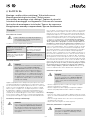 5
5
-
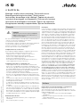 6
6
-
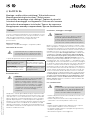 7
7
-
 8
8
-
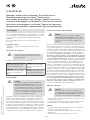 9
9
-
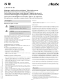 10
10
-
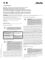 11
11
-
 12
12
-
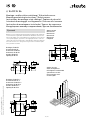 13
13
-
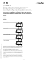 14
14
-
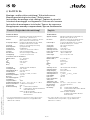 15
15
-
 16
16
-
 17
17
-
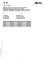 18
18
-
 19
19
-
 20
20


steute EE RC Si 56 Series Mounting And Wiring Instructions
- Tipo
- Mounting And Wiring Instructions
in altre lingue
- English: steute EE RC Si 56 Series
- français: steute EE RC Si 56 Series
- Deutsch: steute EE RC Si 56 Series
- русский: steute EE RC Si 56 Series
- português: steute EE RC Si 56 Series
Documenti correlati
Altri documenti
-
EUCHNER Sensore di sicurezza STA-TW… (Twin) Istruzioni per l'uso
-
-
Beghelli Pluraluce Extreme Manuale utente
-
-
schmersal EX-RDRZ45RT Istruzioni per l'uso
-
Phoenix Contact 3209594 Manuale utente
-
Phoenix Contact 3209565 Istruzioni per l'uso
-
pizzato FD EX7 Series Manuale utente
-
schmersal EX-SHGV/ESS Istruzioni per l'uso
-
Honeywell Istruzioni per l’installazione degli interruttori di sicurezza globali antideflagranti MICRO SWITCH™ GSX Guida d'installazione