
Catalog Number 8544
Sigma 900 Composite Sampler
INSTRUMENT MANUAL
© Hach Company, 2003. All rights reserved. Printed in the U.S.A. eac 07/03 2ed

Visit http: //www.hach.com

Page 3
8544TOC.fm Table of Contents
Table of Contents
Section 1 Specifications..................................................................................................................................... 5
Section 2 General Information.......................................................................................................................... 7
2.1 Instrument Description ........................................................................................................................................ 7
2.2 Interface Connectors........................................................................................................................................... 7
2.2.1 Receptacle Caps ....................................................................................................................................... 7
2.3 Front Panel.......................................................................................................................................................... 8
2.3.1 Keypad and Display................................................................................................................................... 8
2.3.2 Humidity Indicator...................................................................................................................................... 8
2.4 Safety Information ............................................................................................................................................... 9
2.4.1 Use of Hazard Information....................................................................................................................... 10
2.4.2 Precautionary Labels............................................................................................................................... 10
2.4.3 Hazardous Locations............................................................................................................................... 10
2.4.4 Confined Space Entry ............................................................................................................................. 11
2.4.5 Definition of Confined Space ................................................................................................................... 12
Section 3 Installation......................................................................................................................................... 13
3.1 Unpacking the Instrument ................................................................................................................................. 13
3.2 Selecting the Installation Site............................................................................................................................ 13
3.3 Mounting the Sampler....................................................................................................................................... 14
3.4 Attaching the Intake Line................................................................................................................................... 14
3.4.1 Vinyl Intake Tubing................................................................................................................................... 14
3.4.2 Teflon-Lined Polyethylene Intake Line ..................................................................................................... 14
3.5 Setting Up the Intake Line and Strainer ............................................................................................................ 15
3.6 Choosing Bottles............................................................................................................................................... 15
3.7 Installing the Full Bottle Shut-Off ...................................................................................................................... 15
3.8 Power Connections ........................................................................................................................................... 16
3.9 12 V dc.............................................................................................................................................................. 17
3.10 Auxiliary Connection ....................................................................................................................................... 17
Section 4 Operation........................................................................................................................................... 21
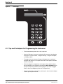
4.1 Keypad and Key Functions................................................................................................................................ 21
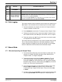
4.2 Tips and Techniques for Programming the Instrument ..................................................................................... 22
4.3 Setting the Time and Date ................................................................................................................................ 23
4.4 Bottle Setup Mode ............................................................................................................................................ 23
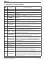
4.5 Explanations of Program Messages ................................................................................................................. 24
4.6 Data Logging..................................................................................................................................................... 25
4.7 Manual Mode .................................................................................................................................................... 25
4.7.1 Manually Operating the Sample Pump .................................................................................................... 25
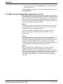
4.8 Measurements Triggered by Liquid Levels or Flow ........................................................................................... 26
4.9 Programming the Sampler for Level Control ..................................................................................................... 27
4.10 Other Displayed Messages ............................................................................................................................. 27
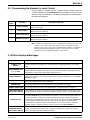
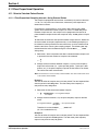
4.11 Flow Proportional Operation ........................................................................................................................... 28
4.11.1 How to Calculate Pulses/Counts ........................................................................................................... 28

Page 4
Table of Contents
8544TOC.fm
Table of Contents
Section 5 Maintenance ..................................................................................................................................... 33
5.1 Cleaning the Sampler ....................................................................................................................................... 33
5.1.1 Cleaning the Sampler Housing................................................................................................................ 33
5.1.2 Cleaning the Sample Bottles ................................................................................................................... 33
5.1.3 Cleaning the Intake Tubing and Pump Tubing ......................................................................................... 33
5.1.4 No Lubrication Required.......................................................................................................................... 33
5.2 Pump Tubing Maintenance................................................................................................................................ 33
5.3 Upgrades, Repairs, General Maintenance ........................................................................................................ 33
5.4 Electrostatic Discharge (ESD) Considerations.................................................................................................. 33
5.5 Internal Maintenance Items............................................................................................................................... 33
5.6 Removing and Opening the Controller.............................................................................................................. 33
5.7 Re-installing the Bottom Panel.......................................................................................................................... 34
5.8 Internal Desiccant Module ................................................................................................................................ 35
5.9 Circuit Board Identification ............................................................................................................................... 35
5.10 Motor/Gear Box............................................................................................................................................... 36
5.11 Internal Case Humidity Indicator..................................................................................................................... 36
5.12 Internal Case Humidity Indicator..................................................................................................................... 36
5.13 Memory Battery .............................................................................................................................................. 36
Section 6 Contact Information for U.S.A. & Outside Europe................................................................... 37
Section 7 Contact Information for Europe................................................................................................... 38
Section 8 Limited Warranty ............................................................................................................................. 39
Section 9 Parts and Accessories................................................................................................................... 41
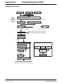
Appendix A Programming Flow Chart ................................................................................................................. 43
Program Flow Chart ......................................................................................................................................... 43
Appendix B Batteries and Chargers .................................................................................................................... 45
Lead-Acid (Gel Cell) Batteries .......................................................................................................................... 45
Nickel-Cadmium Batteries ................................................................................................................................ 46
Appendix C Exploded View Drawings ................................................................................................................. 47
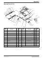
Exploded View (1 of 6) ..................................................................................................................................... 47
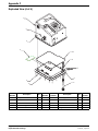
Exploded View (2 of 6) ..................................................................................................................................... 48
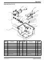
Exploded View (3 of 6) ..................................................................................................................................... 49
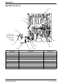
Exploded View (4 of 6) ..................................................................................................................................... 50
Exploded View (5 of 6) ..................................................................................................................................... 51
Exploded View (6 of 6) ..................................................................................................................................... 52

Page 5
8544specs.fm Specifications
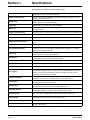
Section 1 Specifications
Specifications are subject to change without notice.
Controller Dimensions
Height: 34 cm (13.5 in.), Width 28 cm (11 in.), Depth 20.3 cm (8 in.) without wall
bracket, 33 cm (13 in.) deep with wall bracket
Pump/Controller Housing
High impact injection molded ABS: submersible, watertight, dust tight, corrosion
and ice resistant; NEMA 4X, 6
Sample Pump
High speed peristaltic, dual roller, with 9.53 ID x 15.9 mm OD (3/8 in. x 5/8 in.)
medical grade silicone rubber pump tube.
Pump Body Impact/corrosion resistant, glass reinforced Delrin
Vertical Lift
8.23 m (27 ft) maximum. Remote pump option recommended for lifts from 6.7 to
10.7 m (22 to 35 ft)
Sample Transport Velocity 61 mm/sec. (2 ft/sec.) minimum, at 4.6 m (15 ft) vertical lift in a 3/8 in. ID intake tube
Pump Flow Rate 60 mL/sec at 0.91 m (3 ft) vertical lift in a 3/8 in. ID intake tube
Sample Volume Programmed in milliliters, in one mL increments from 10 to 9999 mL
Sample Volume Repeatability
From 0.3 to 6.7 m (1 to 22 ft) vertical lift +/-5 mL typical for a 100 mL sample (+/-
5%)
Sampling Modes Supports 1 bottle. Composite Time, Composite Flow, and Level Actuation
Interval Between Samples
Selectable in single increments from 1 to 9999 flow pulses (momentary contact
closure 25 msec. or 5-12 V dc pulse; 4-20 mA interface optional), or 1 to 9999
minutes in one minute increments.
Intake Purge
Air purged automatically before and after each sample; duration automatically
compensated for varying intake line lengths.
Control Panel
18 key, 31 function membrane switch keypad with 18 character alphanumeric, liquid
crystal display. Self prompting/menu driven program.
Internal Clock Indicated real time and date; 0.007% time base accuracy
Programmable Delay Programmable sampler start time/date
Manual Sample Initiates a sample collection independent of program process
Data Logging
Records program start time and date, stores up to 400 sample collection
times/dates, all program entries, operational status including number of minutes or
pulses to next sample, bottle number, number of samples collected, number
remaining, sample identification number.
Automatic Shutdown
Composite Mode: After preset number of samples have been delivered to
composite container, from 1 to 9999 samples, or upon full container.
Intake Tubing
6.4 mm (1/4 in.) and 9.5 mm (3/8 in.) ID vinyl to 9.5 mm (3/8 in.) ID Teflon-lined
polyethylene with protective outer cover
Intake Strainers
Choice of Teflon and 316 stainless construction, and all 316 stainless steel in
standard size and low profile for shallow depth applications
Power Requirements
12 V dc-supplied by optional ac power converter or battery. Average current draw
with pump running: 2.25 amps dc, without pump running: 4 mA dc
ac Power Backup
Rechargeable 6 amp-hour gel lead acid battery takes over automatically with ac
line power failure. Integral trickle charger maintains battery at full charge
Internal Battery
1.5 V
dc
lithium battery; maintains program logic and real time clock for five years.
Internal battery current draws less than 40 micro amps
Overload Protection 5 amp dc line fuse; ac power pack; internal 1 amp ac line fuse
Temperature Range
General use: 0° to 50° C (32° to 122° F). LCD display operated from –10° to 70° C;
Storage –40° to 80° C

Visit http: //www.hach.com

Page 7
8544intro.fm General Information
Section 2 General Information
2.1 Instrument Description
The instrument is designed to automatically collect and preserve samples
from a liquid source. The sampler is suitable for collection of conventional and
toxic pollutants and suspended solids.
The sampler collects samples on either a timed cycle basis, or in proportion to
flow when used in conjunction with a flow meter (flow meter connected to the
auxiliary connector). In the timed cycle mode, the interval between samples is
controlled by an integral quartz crystal clock. The sample interval may be set
from 1 to 9999 minutes, in one minute increments.
In the flow proportional mode, via an external flow meter, the interval between
samples may be set from 1 to 9999 flow pulses, in one pulse increments.
where each pulse represents a specific flow volume interval.
The number of minutes or flow intervals remaining unit the next sample is
shown on the control display. The program can be delayed by entering the
desired starting time and date on the sampler keypad.
The sampler utilizes a high speed peristaltic pump, for collection of the
sample liquid. The pump body is constructed of impact and corrosion
resistant plastic. Tubing is held firmly in place by the pump body haves-no
clamps are required. The intake line is air purged before and after each
sample. The duration of the pre and post sample purge automatically
compensates for different intake line lengths. The pump tubing is 0.95 cm
(3/8
in.) ID X 0.32 cm (1/8 in.) wall medical grade silicone rubber. Although
the pump is capable of vertical lifts up to 8.2 m (27 ft), lifts greater than 6.7 m
(22 ft) are not recommended unless the Remote Pump option is utilized. The
pump produces a sample transport velocity of 1 mps (3.3 fps) at 1 m (3 ft)
vertical lift. The sample is under pumped flow at all times from the source
stream to the sample container, thereby keeping solids in suspension.
2.2 Interface Connectors
The interface connectors are located on the left side of the controller housing.
The sampler comes standard with two interface receptacles:
• 12 V dc (Power Input)
• Auxiliary (Multi-purpose input/output port)
2.2.1 Receptacle Caps
Interface receptacles are covered with push-on receptacle caps. These caps
protect the connector pins from dirt and moisture and should be attached to
any receptacle not in use.

Page 8
Front Panel
8544intro.fm
Section 2
Figure 1 Interface Connectors
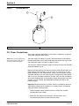
2.3 Front Panel
The front panel consists of the keypad, liquid crystal display, and the internal
case humidity indicator (
Figure 2).
2.3.1 Keypad and Display
The sampler controller is equipped with a 24 character alphanumeric liquid
crystal display which automatically steps the user through the program
settings.
2.3.2 Humidity Indicator
The internal case humidity indicator (Cat. No. 2660) turns pink when the
internal case humidity exceeds 60 percent.
The sampler is equipped with an internal desiccant module (Cat. No. 8849) to
absorb any humidity trapped in the case during final assembly. Under normal
operating conditions, this desiccant provides long-term protection against
condensed moisture inside the case.
Replacement of the internal desiccant module is only necessary if the
indicator turns pink. See to
section 5.8 on page 35 for details.
1. 12 V
dc
2. Auxiliary
1
2

Section 2
Page 9
8544intro.fm Safety Information
Figure 2 900 Composite Sampler
2.4 Safety Information
Please read this entire manual before unpacking, setting up, or operating this
instrument.
Pay particular attention to all danger and caution statements. Failure to do so
could result in serious injury to the operator or
damage to the equipment.
To ensure the protection provided by this equipment is not impaired, do not
use or install this equipment in any manner other than that which is specified
in this manual.
1. Function Key 5. Power On Indicator LED
2. Peristaltic Pump 6. Desiccant Indicator
3. Peristaltic Pump Tubing 7. 24-character Alphanumeric Liquid Crystal Display
4. Tubing Clamp
1
3
4
5
6
7
2

Page 10
Safety Information
8544intro.fm
Section 2
2.4.1 Use of Hazard Information
If multiple hazards exist, this manual will use the signal word (Danger,
Caution, Note) corresponding to the greatest
hazard.
DANGER
Indicates a potentially or imminently hazardous situation which, if not avoided, could result in
death or serious injury.
CAUTION
Indicates a potentially hazardous situation that may result in minor or moderate injury.
NOTE
Information that requires special emphasis.
2.4.2 Precautionary Labels
Read all labels and tags attached to the instrument. Personal injury or
damage to the instrument could occur if not
observed.
2.4.3 Hazardous Locations
The 900 Composite Sampler is not approved for use in hazardous locations
as defined in the National Electrical Code.
DANGER
Although some Hach products are designed and certified for installation in
hazardous locations as defined by the National Electrical Code, many Hach
products are not suitable for use in hazardous locations. It is the responsibility
of the individuals who are installing the products in hazardous locations to
determine the acceptability of the product for the environment. Additionally, to
ensure safety, the installation of instrumentation in hazardous locations must be
per the manufacturer's control drawing specifications. Any modification to the
instrumentation or the installation is not recommended and may result in life
threatening injury and/or damage to facilities.
This symbol, if noted on the instrument, references the instruction manual for operation
and/or
safety information.
This symbol, when noted on a product enclosure or barrier, indicates that a risk of electrical shock
and/or electrocution exists and indicates that only individuals qualified to work with hazardous voltages
should open the enclosure or remove the barrier.
This symbol, when noted on the product, identifies the location of a fuse or current limiting device.
This symbol, when noted on the product, indicates that the marked item can be hot and should not be
touched without care.
This symbol, when noted on the product, indicates the presence of devices sensitive to Electro-static
Discharge and indicates that care must be taken to prevent damage to them.
This symbol, when noted on the product, identifies a risk of chemical harm and indicates that only
individuals qualified and trained to work with chemicals should handle chemicals or perform
maintenance on chemical delivery systems associated with the equipment.
This symbol, if noted on the product, indicates the need for protective eye wear.
This symbol, when noted on the product, identifies the location of the connection for Protective Earth
(ground).

Section 2
Page 11
8544intro.fm Safety Information
DANGER
Bien que certains produits Hach soient conçus et certifiés pour être installés
dans des endroits dangereux tels que définis par le National Electric Code, de
nombreux produits Hach ne conviennent pas pour de tels endroits. Il relève de la
responsabilité des personnes qui placent les produits dans des endroits
dangereux de déterminer s'ils sont adaptés à cet environnement. En outre, à des
fins de sécurité, le placement de machines dans des endroits dangereux doit
s'effectuer dans le respect des consignes des schémas de contrôle du fabricant.
Toute modification apportée aux machines ou tout déplacement de celles-ci est
déconseillé, car susceptible de provoquer des accidents matériels et/ou
corporels.
PELIGRO
Aunque algunos productos Hach están diseñados y homologados para su
instalación en entornos peligrosos, entendidos éstos conforme a la definición
del “National Electrical Code” (Reglamento Eléctrico Nacional), muchos de los
productos Hach no son aptos para su utilización en lugares peligrosos. Es
responsabilidad de quienes instalen los productos en entornos peligrosos el
asegurarse de la idoneidad de dichos productos para este tipo de entorno.
Además, para garantizar la seguridad, la instalación de los instrumentos en
lugares peligrosos deberá realizarse conforme a las especificaciones del plano
del fabricante. Se desaconseja cualquier modificación de los instrumentos o de
la instalación, ya que podría provocar lesiones corporales graves, e incluso
fatales, y/o daños materiales a los equipos.
GEFAHR
Einige Hach-Produkte sind für den Einbau in explosionsgefährdeten Bereichen
gemäß den Festlegungen des National Electrical Code speziell geprüft und
zugelassen. Dies gilt jedoch keineswegs für das gesamte Hach-Produktangebot.
Die Entscheidung, ob ein Produkt für den Einsatz in explosionsgefährden
Bereichen geeignet ist oder nicht, bleibt in die Verantwortung des jeweiligen
Installateurs gestellt. Im Interesse der Sicherheit ist es zudem erforderlich, dass
ein etwaiger Einbau des Geräts in explosionsgefährdeten Bereichen genau nach
den Steuerungsanlagen-Zeichnungen des Herstellers erfolgt. Von der Vornahme
von Änderungen an meß- bzw. regeltechnischen Geräten bzw. abweichender
Installation wird dringend abgeraten, da hierdurch lebensbedrohliche Personen-
und/oder Sachschäden verursacht werden können!
PERICOLO
Nonostante alcuni prodotti Hach, siano predisposti e certificati per
l'installazione in ambienti pericolosi, come previsto dal Codice Normativo
Nazionale che concerne l'elettricità, è sconsigliabile utilizzare prodotti Hach in
ambienti considerati pericolosi. E' diretta responsabilità della persona che
installa lo strumento in un luogo ritenuto “pericoloso” appurare se lo strumento
è compatibile con tale ambiente. Inoltre, per maggior sicurezza, l'installazione
dello strumento in ambienti pericolosi deve seguire le specifiche di
progettazione del produttore. Si deve evitare qualunque manomissione allo
strumento o all'installazione, tali modifiche possono rappresentare una
minaccia per la vita delle persone e creare guasti.
2.4.4 Confined Space Entry
Important Note: The following information is provided to guide users of 900
Composite Samplers on the dangers and risks associated with entry into confined
spaces.
On April 15, 1993, OSHA's final ruling on CFR 1910.146, Permit Required
Confined Spaces, became law. This new standard directly affects more than
250,000 industrial sites in the United States and was created to protect the
health and safety of workers in confined spaces.

Page 12
Safety Information
8544intro.fm
Section 2
2.4.5 Definition of Confined Space
A Confined Space is any location or enclosure that presents or has the
immediate potential to present one or more of the following conditions:
• An atmosphere with less than 19.5% or greater than 23.5% oxygen
and/or more than 10 ppm Hydrogen Sulfide (H
2
S)
• An atmosphere that may be flammable or explosive due to gases, vapors,
mists, dusts, or fibers
• Toxic materials which upon contact or inhalation, could result in injury,
impairment of health, or death
Confined spaces are not designed for human occupancy. They have restricted
entry and contain known or potential hazards.
Examples of confined spaces include manholes, stacks, pipes, vats, switch
vaults, and other similar locations.
Standard safety procedures must always be followed prior to entry into
confined spaces and/or locations where hazardous gases, vapors, mists,
dusts, or fibers may be present.
Before entering any confined space check with your employer for procedures
related to confined space entry.

Page 13
8544install.fm Installation
Section 3 Installation
DANGER
Only qualified personnel should conduct the installation tasks described in this
section of the manual
3.1 Unpacking the Instrument
Remove the sampler from the shipping carton and inspect it for any damage.
Contact Hach Customer Service at 1-800-227-4224 if any items are missing
or damaged.
3.2 Selecting the Installation Site
The sampler is completely self-contained and may be located indoors or
outdoors without protection, between 0 to 50 °C (32 to 120 °F). Follow the
guidelines below and
Figure 3 to allow complete drainage of the intake line
and prevent cross-contamination between samples.
• Install the sampler as close to the source as site conditions permit. This
will increase pump tube life and optimize overall sampler performance.
• Mount the sampler to a stable flat surface using the wall mounting
bracket, Cat. No. 3596 (
Figure 4).
• Install the sampler above the sample source, with the intake tubing
sloping downward to the sample.
• Make sure the tubing is free of kinks or loops.
Figure 3 Placement of the Sampler
1. Slope tubing down to source (no loops, kinks, or excess tubing).
2. Locate strainer in an area of turbulent and well-mixed flow.
1
2
Flow

Page 14
Mounting the Sampler
8544install.fm
Section 3
Figure 4 Wall Mount Bracket
3.3 Mounting the Sampler
Attach the wall mount bracket to a stable panel or wall (Figure 4). Mount the
bracket so the sample display and keypad are easily accessible. Mount the
sampler to the wall bracket using the four screws provided.
3.4 Attaching the Intake Line
3.4.1 Vinyl Intake Tubing
1. Push one end of the clear flexible PVC (vinyl) tube to the tapered end of
the intake strainer, until the tube is within 0.635 cm (¼ in.) of the solid
white Teflon strainer body.
2. Push the other end of the vinyl tube on to the stainless steel fitting
connector end that points away from the pump control housing.
3.4.2 Teflon-Lined Polyethylene Intake Line
The Connection Kit for Teflon-lined Tubing (Cat. No. 2186) contains two
identical assemblies, one for connecting the Teflon-lined tubing to the
stainless steel tubing connector and the other for connecting the intake
strainer.
1. Place the stainless steel hose clamp over the stainless steel fitting until it
abuts the shoulder of the tubing connector. Secure with a tubing clamp.
2. Push the stainless steel fitting into the Teflon-lined tubing until it abuts the
shoulder of the stainless steel fitting.
3. Slide the stainless steel hose clamp over the silicone tubing, then push
the silicone tubing over the stainless steel fitting on the liquid sensor.

Section 3
Page 15
8544install.fm Setting Up the Intake Line and Strainer
4. Slide the tubing clamp over the silicone tubing until it is over the stainless
steel fitting on the liquid sensor. Tighten to secure.
5. Repeat the procedure for the intake strainer.
3.5 Setting Up the Intake Line and Strainer
For each sampling location, the intake line should be as short as practical,
and be free of any sharp bends, coils, or loops. Install the intake line with a
downward slope from the sampler to the sample source because:
• This will assure the complete drainage of the intake line when it is air-
purged before and after each sample, and will help to prevent cross-
contamination of the individual samples.
• Complete drainage is important in freezing conditions, as any liquid slugs
that remain could freeze and plug the line.
Place the sample intake and strainer in the mainstream of the sampling
source, in an area of turbulent and well-mixed flow.
Also, take in account the vertical location of the intake. A position too near the
surface may yield excess lighter materials, while a position too near the
bottom may yield excess heavy materials. The constituents of interest must
be considered when positioning the intake strainer.
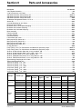
3.6 Choosing Bottles
A broad range of bottle configurations are available for the 900 Composite
Sampler. Refer to
3.7 Installing the Full Bottle Shut-Off
Install the optional full bottle shut-off into the bottle cap using the attached
rubber grommet. Install the full bottle shut-off connector to the mating plug
which is attached tot he sampler back panel. Insert the sample tubing into the
cap of the bottle.
Size Material
9.5 L (3 gal) Polyethylene
11.4 L (2.5 gal) Glass
15.1 (4 gal) Polyethylene
20.1 L (5.5 gal) Polyethylene
22.7 L (6 gal) Polyethylene

Page 16
Power Connections
8544install.fm
Section 3
Figure 5 Full Bottle Shut-off
3.8 Power Connections
The sampler controller operated on 12 V dc which is supplied by an optional
ac/dc power converter and/or battery.
Note: Make sure both rubber hold-
downs are attached to the clips at
each end of the power supply.
The power supply (or battery) is placed in the compartment located directly
behind the controller. Pull the rubber hold-downs up and over the clips at each
end of the power supply (or battery) to hold it in place.
The short 2-pin cable on the power supply (or battery) connects the controller
receptacle labeled 12 V dc.
Batteries available from the manufacturer include a lead-acid gel battery, and
nickel-cadmium (Ni-Cad) battery (Cat. No. 1416). The 120 V ac to 12 V dc
power converter (Cat. No. 1440) includes a built-in lead-acid battery charger.
The Power Converter (Cat. No. 1443) contains a charger for Ni-Cad batteries.
230 V ac and 12 V dc power converters (Cat. No. 1441) are also available but
do not come equipped with a built-in battery charger. Stand-alone, wall mount
chargers are also available. See APPENDIX for details on batteries and
battery charging.
Important: Whenever electricity is present, there is a possibility of electrical
shock. Before connecting the sampler to an ac power source, the following
safety precautions should be taken:
• Check the power source to make sure that it satisfies the ac power
requirements of the sampler.
• Make sure that all electrical installations and connections are in
accordance with national and local electrical codes.
1. Sample Tubing 2. Full Bottle Shut-off
1
2

Section 3
Page 17
8544install.fm 12 V dc
• Before performing any maintenance, disconnect the sampler from the
power source.
• Do not attempt to make any connection or otherwise handle the electrical
components of the sampler when connected to ac line power if the
immediate area is wet, or if hands or clothing are wet.
• If the circuit breaker or fuse in the ac power source is tripped, determine
the cause before restoring power to the sampler.
• Make sure the power circuit is grounded and protected with a Ground
Fault Interrupter (GFI).
3.9 12 V dc
This connection is for supplying power to the sampler controller electronics.
Power is normally supplied to the sampler controller electronics from either a
battery or a power supply located in the pocket directly behind the sampler
controller housing.
In the event of a power outage, an optional 12 V dc battery backup is available
(Cat. No. 1803). This power backup maintains power to the sampler when ac
power fails.
3.10 Auxiliary Connection
The auxiliary interface connector is a general purpose input/output port. Each
signal is described in
Tabl e 2 .
Table 1 12 V dc Connector Pin Assignments
Pin Signal Description
A ground
B 12 to 17 V dc unregulated
Table 2 Auxiliary Pin Assignments
Pin Signal Description Wire Color Purpose Rating
A 12 V dc White
This pin can be used to power an external device or flow meter. Must
be used in conjunction with Pin B (ground).
13.8 V dc
nominal
B ground Blue
Connected to dc ground and is isolated from the earth ground found
in the ac power line.
C Flow Pulse Input Ye l l o w
With the sampler is in Flow Proportional mode and connected to an
external flow meter, a 5 to 12 V dc input pulse lasting at least 25
milliseconds will cause the sampler to decrement one count. The
sampler is capable of accumulating from 1 to 9999 input pulses.
The 12 V dc line found on Pin A can be used directly with a simple
contact closure to Pin C or an external 5 to 12 V dc pulse may be
applied providing the ground side of the external signal is connected
to the sampler ground at Pin B. This count is actuated at the
beginning of the input signal (the leading edge of the pulse).
5 to 17 V dc
pulse with
duration of
at least
25 ms.

Page 18
Auxiliary Connection
8544install.fm
Section 3
Contact Closures
The sampler controller is capable of accumulating 1 to 9999 contact closures.
Each contact closure output from a flow meter represents a specific flow
volume.
Note: The sampler provides 12 V dc
on Pin A of the Auxiliary Receptacle
and this voltage is pulsed back to
Pin C each time the contact closes
on the external flow meter. The
external flow meter must provide a
dry contact closure.
Some flow meters have an adjustable output, i.e. one contact closure for
every 100, 500, 1000, 10, 000 gallons of flow, etc., while others have a fixed
output. In either case, the contact closure signal is sent more frequently for
high flow rates, and less frequently for low flow rates. The sample frequency
will increase as the flow rate increases and likewise, will decrease as the rate
of flow decreases, thus taking samples in proportion to flow rate.
To connect the sampler to a flow meter, use Signal Cable (Cat. No. 940 or
540). To connect another brand of flow meter, use the Open-ended Signal
Cable (Cat. No. 941 or 541). A contact closure input signal corresponds to
Pins A and C on the Flow Meter/Auxiliary receptacle, and signal cable
connector. The signal cable wires are white and yellow respectively. Polarity is
not important unless the same closure signal is sent to more than one
sampler.
4–20 mA Input
Note: Older model 4–20 mA
interfaces (Cat. No. 913) require
correct loop polarity to properly
work. The newer generation
(Cat. No. 2020 series) interfaces are
not sensitive to loop polarity.
An optional interface unit is available (Cat. No. 2021) which converts a
4–20 mA flow meter output into a 12 V dc pulses. At 20 mA (100% flow rate),
the interface sends ten pulses per minute; at 4 mA (0% flow rate), the
interface sends zero pulses.
The interface has a 0.9 m (3 ft) cable with connector on one end, and a 3 m
(10 ft) cable with two open wire leads on the other. Insert the connector into
the sampler receptacle labeled “AUXILIARY”, located on the left side of the
control housing. For the 3 m (10 ft) cable, the wire with clear insulation is
POSITIVE (+) and the wire with black insulation is NEGATIVE (–).
D
Liquid Level
Actuator/Auxiliary
Control Input
Black
This line is held at 5 V dc inside the sampler. When shorted to
ground (Pin B), a signal is sent to the microprocessor inside the
sampler causing it to “wake up” and begin or resume the sampling
program. It can be used in conjunction with a simple level float switch
to actuate the sampler when liquid id present or to take over after a
second sampler had finished its program. It may also be used with
any device (such as pH meter) which produces a dry contact output
to control the sampler in response to some user defined condition
(i.e. high or low pH); must be used in conjunction with Pin B
(ground).
24 V dc
(max) at
100 mA
(max)
E Special Output Red
Normally at 0 V dc, this line switches to 12 V dc upon any of the
selected event described in SECTION, PROGRAMMING.
N/A
F
Program Complete
Output
Green
Normally an open circuit, this line switches to ground for 90 seconds
at the conclusion of the sampling program. Used to “wake up”
another sampler to take over sampling or to signal an operator or
datalogger upon the completion of the sampling program.
N/A
Table 2 Auxiliary Pin Assignments
Pin Signal Description Wire Color Purpose Rating

Section 3
Page 19
8544install.fm Auxiliary Connection
Figure 6 4–20 mA Interface and Pulse Duration Input
For details on programming the sampler for flow proportional operation, refer
to SECTION.
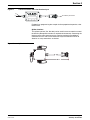
Splitter Interface
This splitter interface (Cat. No. 939) can be used if access to more than one of
the Auxiliary Receptacle functions is required simultaneously. Connecting the
interface to the 6-pin connector on the sampler provides three additional
connectors for use. Two or more interfaces may be connected in series to
allow for as many connections as desired.
Figure 7 Splitter Interface
To Auxillary Connector
(-)
(+)

Visit http: //www.hach.com
La pagina si sta caricando...
La pagina si sta caricando...
La pagina si sta caricando...
La pagina si sta caricando...
La pagina si sta caricando...
La pagina si sta caricando...
La pagina si sta caricando...
La pagina si sta caricando...
La pagina si sta caricando...
La pagina si sta caricando...
La pagina si sta caricando...
La pagina si sta caricando...
La pagina si sta caricando...
La pagina si sta caricando...
La pagina si sta caricando...
La pagina si sta caricando...
La pagina si sta caricando...
La pagina si sta caricando...
La pagina si sta caricando...
La pagina si sta caricando...
La pagina si sta caricando...
La pagina si sta caricando...
La pagina si sta caricando...
La pagina si sta caricando...
La pagina si sta caricando...
La pagina si sta caricando...
La pagina si sta caricando...
La pagina si sta caricando...
La pagina si sta caricando...
La pagina si sta caricando...
La pagina si sta caricando...
La pagina si sta caricando...
-
 1
1
-
 2
2
-
 3
3
-
 4
4
-
 5
5
-
 6
6
-
 7
7
-
 8
8
-
 9
9
-
 10
10
-
 11
11
-
 12
12
-
 13
13
-
 14
14
-
 15
15
-
 16
16
-
 17
17
-
 18
18
-
 19
19
-
 20
20
-
 21
21
-
 22
22
-
 23
23
-
 24
24
-
 25
25
-
 26
26
-
 27
27
-
 28
28
-
 29
29
-
 30
30
-
 31
31
-
 32
32
-
 33
33
-
 34
34
-
 35
35
-
 36
36
-
 37
37
-
 38
38
-
 39
39
-
 40
40
-
 41
41
-
 42
42
-
 43
43
-
 44
44
-
 45
45
-
 46
46
-
 47
47
-
 48
48
-
 49
49
-
 50
50
-
 51
51
-
 52
52


Hach 900 Manuale utente
- Tipo
- Manuale utente
- Questo manuale è adatto anche per
in altre lingue
- English: Hach 900 User manual
Documenti correlati
-
 Hach SIGMA 900 Manuale utente
-
 Hach AS950 AWRS Basic Installation And Maintenance
-
 Hach AS950 Basic Installation And Maintenance
-
 Hach AS950 Basic Operations
-
 Hach 29971-72 Manuale utente
-
 Hach QbD1200 AutoSampler Manuale utente
-
 Hach BODTrak II Basic User Manual
-
 Hach FL902 Basic User Manual
-
 Hach QbD1200 AutoSampler Manuale utente
-
 Hach AV9000S Manuale utente


