
Catalog Number 8837
Sigma 900 All Weather Refrigerated Sampler
USER MANUAL
March 2006, Edition 7
© Hach Company, 2002, 2003, 2006. All rights reserved. Printed in the U.S.A. eac/jk

Visit http: //www.hach.com

Page 3
8837TOC.fm Table of Contents
Table of Contents
Safety Precautions.................................................................................................................................................... 6
Specifications............................................................................................................................................................ 9
Section 1 Introduction .......................................................................................................................................11
1.1 Instrument Description.......................................................................................................................................11
1.2 Principle Operation ............................................................................................................................................11
1.2.1 Accurate, Repeatable Sample Volumes...................................................................................................11
1.2.2 Intake Tube Pre-Rinse............................................................................................................................. 12
1.2.3 Sample Retry........................................................................................................................................... 12
Section 2 Installation......................................................................................................................................... 15
2.1 Selecting the Installation Site............................................................................................................................ 15
2.2 Installing the All Weather Refrigerated Sampler............................................................................................... 15
2.3 Installing the Pump Tube in the Sensor Body................................................................................................... 16
2.3.1 Attaching the Intake Line......................................................................................................................... 17
2.4 Setting Up the Intake Line and Strainer ............................................................................................................ 19
2.5 Bottles and Retainers........................................................................................................................................ 19
2.6 Power Connections........................................................................................................................................... 19
2.7 Flow Proportional Operation ............................................................................................................................. 20
2.7.1 Contact Closure Input.............................................................................................................................. 20
2.7.2 Pulse Input............................................................................................................................................... 20
2.7.3 4–20 mA Input......................................................................................................................................... 20
2.7.4 Auxiliary Receptacle................................................................................................................................ 21
Section 3 Connecting to External Devices .................................................................................................. 23
3.1 Using the 12 V dc Connection .......................................................................................................................... 23
3.2 Using the Auxiliary Connection......................................................................................................................... 23
3.2.1 Splitter Interface....................................................................................................................................... 24
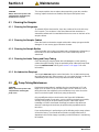
Section 4 Maintenance ..................................................................................................................................... 27
4.1 Cleaning the Sampler ....................................................................................................................................... 27
4.1.1 Cleaning the Refrigerator ........................................................................................................................ 27
4.1.2 Cleaning the Sampler Cabinet................................................................................................................. 27
4.1.3 Cleaning the Sample Bottles ................................................................................................................... 27
4.1.4 Cleaning the Intake Tubing and Pump Tubing......................................................................................... 27
4.1.5 No Lubrication Required.......................................................................................................................... 27
4.2 Pump Tubing Maintenance............................................................................................................................... 27
4.2.1 Tubing Life Estimates.............................................................................................................................. 28
4.2.2 Replacing Pump Tubing .......................................................................................................................... 29
4.3 Humidity Indicator ............................................................................................................................................. 29
4.4 Desiccant Replacement.................................................................................................................................... 29
4.5 Refrigerated Compartment Thermal Control System Calibration...................................................................... 29
4.6 Fuse Replacement............................................................................................................................................ 30
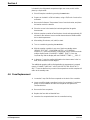
4.7 Resetting the Circuit Breaker............................................................................................................................ 31
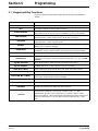
Section 5 Programming.................................................................................................................................... 35
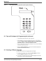
5.1 Keypad and Key Functions............................................................................................................................... 35

Page 4
Table of Contents
8837TOC.fm
Table of Contents
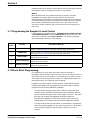
5.2 Tips and Techniques for Programming the Instrument ..................................................................................... 36
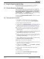
5.3 Selecting a Different Language......................................................................................................................... 36
5.4 Using the Sampler for the First Time ................................................................................................................ 37
5.4.1 Getting the Sampler into “Standby State”................................................................................................ 37
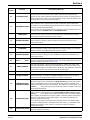
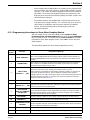
5.5 Explanations of Program Messages ................................................................................................................. 38
5.6 Setting the Time and Date ................................................................................................................................ 41
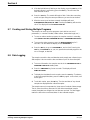
5.7 Creating and Storing Multiple Programs ........................................................................................................... 42
5.8 Data Logging..................................................................................................................................................... 42
5.9 Manual Mode .................................................................................................................................................... 43
5.9.1 Manually Operating the Sample Pump.................................................................................................... 43
5.9.2 Manually Operating the Distributor Arm .................................................................................................. 43
5.10 Measurements Triggered by Liquid Levels or Flow ........................................................................................ 43
5.11 Programming the Sampler for Level Control................................................................................................... 44
5.12 Storm Water Programming.............................................................................................................................. 44
5.12.1 Programming Instructions for Storm Water Sampling Routine.............................................................. 45
5.13 Special Outputs............................................................................................................................................... 46
5.13.1 Programming the Sampler for Special Outputs..................................................................................... 47
5.13.2 Other Displayed Messages for Special Outputs.................................................................................... 47
5.14 Advanced Program Features.......................................................................................................................... 48
5.14.1 Program Start/Stop ................................................................................................................................ 49
5.14.2 Variable Interval..................................................................................................................................... 49
5.14.3 Two-, Four-, and Eight-Bottle Sampling................................................................................................. 49
5.14.4 Timed Bottle........................................................................................................................................... 49
5.14.5 Timed Bottle—Pre-Advanced Mode...................................................................................................... 50
5.15 Flow Proportional Operation ........................................................................................................................... 50
5.15.1 How to Calculate Pulses/Counts........................................................................................................... 50
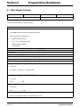
Section 6 Programming Worksheets ............................................................................................................ 55
6.1 Main Sampler Program..................................................................................................................................... 55
6.2 Volume Calibration Sheet ................................................................................................................................. 57
6.3 Stormwater Setup Sheet................................................................................................................................... 58
6.4 Stormwater Program Checklist ........................................................................................................................ 59
6.5 Final Check List ................................................................................................................................................ 60
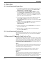
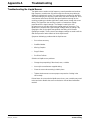
Appendix A Troubleshooting............................................................................................................................... 61
Troubleshooting the Liquid Sensor................................................................................................................... 61
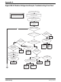
Sigma 900 All Weather Refrigerated Sampler Troubleshooting Flow Chart .................................................... 62
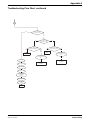
Troubleshooting Flow Chart, continued............................................................................................................ 63
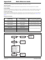
Appendix B Quick Reference Guide.................................................................................................................... 65
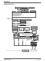
Program Flow Chart ......................................................................................................................................... 66
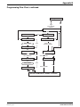
Programming Flow Chart, continued................................................................................................................ 67
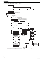
Level Control/First Flush Flow Chart ................................................................................................................ 68
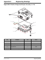
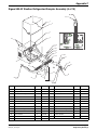
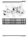
Appendix C Engineering Drawings...................................................................................................................... 69
Sigma 900 All Weather Refrigerated Sampler Assembly (1 of 15)...................................................................69
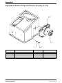
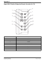
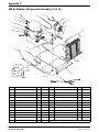
Sigma 900 All Weather Refrigerated Sampler Assembly (2 of 15)...................................................................70
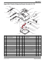
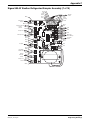
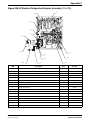
Sigma 900 All Weather Refrigerated Sampler Assembly (3 of 15)...................................................................71
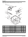
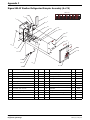
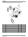
Sigma 900 All Weather Refrigerated Sampler Assembly (4 of 15)...................................................................72

Table of Contents
Page 5
8837TOC.fm Table of Contents
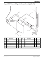
Sigma 900 All Weather Refrigerated Sampler Assembly (5 of 15)...................................................................73
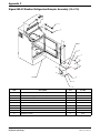
Sigma 900 All Weather Refrigerated Sampler Assembly (6 of 15)...................................................................74
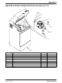
Sigma 900 All Weather Refrigerated Sampler Assembly (7 of 15)...................................................................75
Sigma 900 All Weather Refrigerated Sampler Assembly (8 of 15)...................................................................76
Sigma 900 All Weather Refrigerated Sampler Assembly (9 of 15)...................................................................77
900 All Weather Refrigerated Assembly (10 of 15) .......................................................................................... 78
Sigma 900 All Weather Refrigerated Sampler Assembly (11 of 15)................................................................. 79
Sigma 900 All Weather Refrigerated Sampler Assembly (12 of 15)................................................................. 80
Sigma 900 All Weather Refrigerated Sampler Assembly (13 of 15)................................................................. 81
Sigma 900 All Weather Refrigerated Sampler Assembly (14 of 15)................................................................. 82
Sigma 900 All Weather Refrigerated Sampler Assembly (15 of 15)................................................................. 83
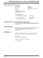
Parts and Accessories ............................................................................................................................................ 87
Contact Information for U.S.A. and Outside Europe............................................................................................... 89
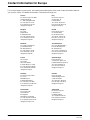
Contact Information for Europe............................................................................................................................... 90
Warranty ................................................................................................................................................................. 91
Index ....................................................................................................................................................................... 92

Page 6
Safety Precautions
8837saf.fm
Safety Precautions
Please read this entire manual before unpacking, setting up, or operating this instrument.
Pay particular attention to all danger and caution statements. Failure to do so could result in serious injury to the
operator or damage to the equipment.
To ensure the protection provided by this equipment is not impaired, do not use or install this equipment in any
manner other than that which is specified in this manual.
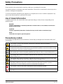
Use of Hazard Information
If multiple hazards exist, this manual will use the signal word (Danger, Caution, Note) corresponding to the
greatest hazard.
DANGER
Indicates a potentially or imminently hazardous situation which, if not avoided, could result in
death or serious injury.
CAUTION
Indicates a potentially hazardous situation that may result in minor or moderate injury.
NOTE
Information that requires special emphasis.
Precautionary Labels
Read all labels and tags attached to the instrument. Personal injury or damage to the instrument could occur if
not observed.
This symbol, if noted on the instrument, references the instruction manual for operation
and/or safety information.
This symbol, when noted on a product enclosure or barrier, indicates that a risk of electrical shock
and/or electrocution exists and indicates that only individuals qualified to work with hazardous voltages
should open the enclosure or remove the barrier.
This symbol, when noted on the product, identifies the location of a fuse or current limiting device.
This symbol, when noted on the product, indicates that the marked item can be hot and should not be
touched without care.
This symbol, when noted on the product, indicates the presence of devices sensitive to Electro-static
Discharge and indicates that care must be taken to prevent damage to them.
This symbol, when noted on the product, identifies a risk of chemical harm and indicates that only
individuals qualified and trained to work with chemicals should handle chemicals or perform
maintenance on chemical delivery systems associated with the equipment.
This symbol, if noted on the product, indicates the need for protective eye wear.
This symbol, when noted on the product, identifies the location of the connection for Protective Earth
(ground).

Safety Precautions
Page 7
8837saf.fm Safety Precautions
Hazardous Locations
The Sigma 900 All Weather Refrigerated Sampler is not approved for use in
hazardous locations as defined in the National Electrical Code.
DANGER
Although some Sigma products
are designed and certified for
installation in hazardous
locations as defined by the
National Electrical Code, many
Sigma products are not suitable
for use in hazardous locations. It
is the responsibility of the
individuals who are installing the
products in hazardous locations
to determine the acceptability of
the product for the environment.
Additionally, to ensure safety, the
installation of instrumentation in
hazardous locations must be per
the manufacturer's control
drawing specifications. Any
modification to the
instrumentation or the
installation is not recommended
and may result in life threatening
injury and/or damage to facilities.
DANGER
Bien que certains produits Sigma soient conçus et certifiés pour être installés
dans des endroits dangereux tels que définis par le National Electric Code, de
nombreux produits Sigma ne conviennent pas pour de tels endroits. Il relève de
la responsabilité des personnes qui placent les produits dans des endroits
dangereux de déterminer s'ils sont adaptés à cet environnement. En outre, à des
fins de sécurité, le placement de machines dans des endroits dangereux doit
s'effectuer dans le respect des consignes des schémas de contrôle du fabricant.
Toute modification apportée aux machines ou tout déplacement de celles-ci est
déconseillé, car susceptible de provoquer des accidents matériels et/ou
corporels.
PELIGRO
Aunque algunos productos Sigma están diseñados y homologados para su
instalación en entornos peligrosos, entendidos éstos conforme a la definición
del “National Electrical Code” (Reglamento Eléctrico Nacional), muchos de los
productos Sigma no son aptos para su utilización en lugares peligrosos. Es
responsabilidad de quienes instalen los productos en entornos peligrosos el
asegurarse de la idoneidad de dichos productos para este tipo de entorno.
Además, para garantizar la seguridad, la instalación de los instrumentos en
lugares peligrosos deberá realizarse conforme a las especificaciones del plano
del fabricante. Se desaconseja cualquier modificación de los instrumentos o de
la instalación, ya que podría provocar lesiones corporales graves, e incluso
fatales, y/o daños materiales a los equipos.
GEFAHR
Einige Sigma-Produkte sind für den Einbau in explosionsgefährdeten Bereichen
gemäß den Festlegungen des National Electrical Code speziell geprüft und
zugelassen. Dies gilt jedoch keineswegs für das gesamte Sigma-
Produktangebot. Die Entscheidung, ob ein Produkt für den Einsatz in
explosionsgefährden Bereichen geeignet ist oder nicht, bleibt in die
Verantwortung des jeweiligen Installateurs gestellt. Im Interesse der Sicherheit
ist es zudem erforderlich, dass ein etwaiger Einbau des Geräts in
explosionsgefährdeten Bereichen genau nach den Steuerungsanlagen-
Zeichnungen des Herstellers erfolgt. Von der Vornahme von Änderungen an
meß- bzw. regeltechnischen Geräten bzw. abweichender Installation wird
dringend abgeraten, da hierdurch lebensbedrohliche Personen- und/oder
Sachschäden verursacht werden können!
PERICOLO
Nonostante alcuni prodotti Sigma, siano predisposti e certificati per
l'installazione in ambienti pericolosi, come previsto dal Codice Normativo
Nazionale che concerne l'elettricità, è sconsigliabile utilizzare prodotti Sigma in
ambienti considerati pericolosi. E' diretta responsabilità della persona che
installa lo strumento in un luogo ritenuto “pericoloso” appurare se lo strumento
è compatibile con tale ambiente. Inoltre, per maggior sicurezza, l'installazione
dello strumento in ambienti pericolosi deve seguire le specifiche di
progettazione del produttore. Si deve evitare qualunque manomissione allo
strumento o all'installazione, tali modifiche possono rappresentare una
minaccia per la vita delle persone e creare guasti.

Page 8
Safety Precautions
8837saf.fm
Safety Precautions
Confined Space Entry
Important Note: The following information is provided to guide users of Sigma 900 All
Weather Refrigerated Samplers on the dangers and risks associated with entry into
confined spaces.
On April 15, 1993, OSHA's final ruling on CFR 1910.146, Permit Required
Confined Spaces, became law. This new standard directly affects more than
250,000 industrial sites in the United States and was created to protect the
health and safety of workers in confined spaces.
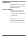
Definition of Confined Space
A Confined Space is any location or enclosure that presents or has the
immediate potential to present one or more of the following conditions:
• An atmosphere with less than 19.5% or greater than 23.5% oxygen
and/or more than 10 ppm Hydrogen Sulfide (H
2
S)
• An atmosphere that may be flammable or explosive due to gases, vapors,
mists, dusts, or fibers
• Toxic materials which upon contact or inhalation, could result in injury,
impairment of health, or death
Confined spaces are not designed for human occupancy. They have
restricted entry and contain known or potential hazards.
Examples of confined spaces include manholes, stacks, pipes, vats, switch
vaults, and other similar locations.
Standard safety procedures must always be followed prior to entry into
confined spaces and/or locations where hazardous gases, vapors, mists,
dusts, or fibers may be present.
Before entering any confined space check with your employer for procedures
related to confined space entry.

Page 9
8837spc.fm Specifications
Specifications
Specifications are subject to change without notice.
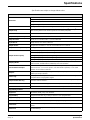
General
Dimensions
Width: 71 cm (28 in.)
Depth: 71 cm (28 in.)
Height: 125 cm (49 in.)
Weight: 79 kg (175 lb)
Cabinet Fiberglass reinforced plastic with beige UV-inhibited polymer laminate
Sample Pump
High speed peristaltic, dual roller, used with custom purchased
3
/8 in. ID by
5
/8 in. OD
Dow Corning Silastic Rx50 medical grade silicone rubber pump tube
Vertical Lift 27 ft maximum (Remote Pump Option recommended for lifts from 22 to 35 ft)
Sample Transport Velocity 2 ft/sec. minimum, at 15 ft vertical lift in a
3
/8 in ID intake tube
Pump Flow Rate 60 mL/sec at 3 ft vertical lift in a
3
/8 in. ID intake line
Liquid Sensor Single sensor, non-contact, ultrasonic
Sample Volume Programmed in milliters, in one mL increments from 10 to 9,999 mL
Sample Volume Repeatability ±5% typical
Sample Volume Capacity
(24) 1 liter polyethylene and/or 350 mL glass bottles
(8) 2.3 liter polyethylene and/or 1.9 liter glass bottles
(4) 3 gallon polyethylene and/or 2½ gallon glass bottles
(2) 3 gallon polyethylene and/or 2½ gallon glass bottles
(1) 6 gallon polyethylene composite container, or 3 gallon poly, or 2.5 gallon glass
Sampling Modes
Multiple Bottle Time, Multiple Bottle Flow, Composite Time, Composite Flow, Flow with
Time Override, Variable Interval, Start/Stop, and Level Actuation
Interval Between Samples
Selectable in single increments from 1 to 9,999 flow pulses (momentary contact
closure 25 msec. or 5–12 V dc pulses; 4–20 mA interface optional), or 1 to 9,999
minutes in one minute increments
Multiplex
Multiple Bottle Mode: Programming allows multiple samples per bottle and/or multiple
bottles per sample collection.
Intake Purge
Air purged automatically before and after each sample; duration automatically
compensated for varying intake lengths
Pump/Controller Housing
NEMA 4X, 6. High impact injection molded ABS; submersible, watertight, dust tight,
corrosion and ice resistant
User Interface 18 key membrane switch keypad; 24 character alphanumeric liquid crystal display
Internal Clock Indicates real time and date; 0.007% time base accuracy
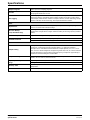
Programming Features
Diagnostics Tests RAM, ROM, pump, and distributor
Program Delay Sampler start at time day, or delay in minutes is user programmable
Program Language English, French, German, Italian, Spanish, Swedish, Czech, Danish, and Dutch
Manual Sample Initiates a sample collection independent of program in progress
Intake Rinse
Intake line automatically rinsed with source liquid prior to each sample, from 1 to 3
rinses.
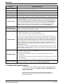
Intake Fault
Sample collection cycle automatically repeated from 1 to 3 times if sample not obtained
on initial attempt.

Page 10
Specifications
8837spc.fm
Specifications
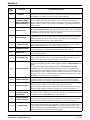
Multiple Programs Stores up to five sampling programs.
Cascade
Allows using two samplers in combination where the first sampler at the completion of
the program initiates the second.
Data Logging
Records program start time and date, stores up to 400 sample collection times/dates,
all program entries, operational status including number of minutes or pulses to the
next sample, bottle number, number of samples collected, number remaining, sample
volume collected, volume remaining, and sample identification number.
Power
Requirements
115 V ac, 60 Hz (230 and 100 V ac optional); Compressor Running Amperage
1.5–2.0 A. Locked rotor current 12 amps.
AC Power Backup
(Pump Controller Only)
Rechargeable 6 amp-hour gel lead acid battery takes over automatically with ac line
power failure. Integral trickle charger maintains battery at full charge (factory installed
option).
Internal Battery 5 year lithium battery maintains program settings and real time clock.
Overload Protection
Controller: 5 amp dc line fuse for pump, 1 amp dc line fuse for ac power connector
Compressor: Thermal overload relay, opens at 110 °C
Environmental
Sample Cooling
Refrigeration: Top mounted compressor/condensor with fan-forced air cooler
condenser; 3-sided wrap-around evaporator plate; 2 in. rigid foam insulation;
microprocessor controlled thermostat maintains sample liquid at (4 °C) ±1 °C; frost
free; non-CFC R134A refrigerant compression gasket door seal; air cooled condenser
is protected against corrosion with a food grade epoxy; all exposed copper tubing is
insulated to avoid sweating and condensation.
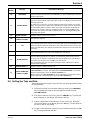
Temperature Range
General Use: -29 °C to +50 °C (-20 °F to 122 °F); with optional controller compartment
heater, -40 °C to +50 °C (-40 °F to 122 °F)
Liquid Crystal Temperature
Range
Operating: -10°to 70 °C (-14° to 158 °F)
Storage: -40° to 80 °C (-40° to 176 °F)
Recovery Time
With door open, one minute in 75 °F ambient and five minutes 4 °C sample
temperature.
Pull Down Time From 24 °C (75 °F) to 4 °C (39 °F), 15 minutes

Page 11
8837int.fm Introduction
Section 1 Introduction
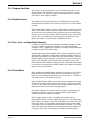
1.1 Instrument Description
The Sigma 900 All Weather Refrigerated Sampler is designed to
automatically collect and preserve samples from a liquid source using
refrigeration. The sampler is suitable for collection of conventional and toxic
pollutants and suspended solids.
The sampler is designed for indoor and outdoor applications. Conforming to
NEMA 4X, 6 standards, the controller withstands submersion, corrosion, and
ice resistance. Refrigeration components are polymer coated, providing
superior corrosive resistance. With the compressor and condenser located
above the refrigerated compartment, heat transfer is directed away from the
compartment. A microprocessor controlled thermal system maintains samples
at EPA mandated 4 °C (39 °F). Top mounted refrigeration components also
minimize exposure to the corrosive plant environments.
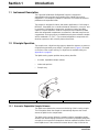
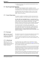
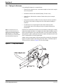
1.2 Principle Operation
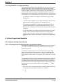
The sampler uses a liquid sensing system to detect the absence or presence
of liquid at the peristaltic pump intake. The liquid sensor (Figure 1) is located
on the front of the control housing. For liquid sensor troubleshooting see
Appendix A on page 61.
The liquid sensing system provides three primary benefits:
• Accurate, repeatable sample volumes
• Intake tube prerinse
• Sample retry
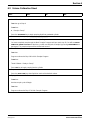
Figure 1 Liquid Sensor
1.2.1 Accurate, Repeatable Sample Volumes
The liquid sensor detects the presence and velocity of the incoming sample.
This information allows the sampler to automatically dispense the correct
amount of liquid into the sample bottle.
The liquid sensing system allows the sampler to deliver repeatable sample
volumes even with changing suction lifts. Each time the peristaltic pump pulls
a sample, the microprocessor determines the time required for liquid to travel
to the liquid sensor. If the suction lift increases due to a drop in level at the
1. Sensor Body 2. Knobs (turn to remove) 3. Sensor Cover
2
1
3

Page 12
Principle Operation
8837int.fm
Section 1
sample source, the time required for liquid to reach the sensor will increase.
The microprocessor automatically compensates for this change by allowing
the peristaltic pump to deliver sample liquid for a corresponding longer period
of time. Conversely, if suction lift decreases due to an increase in level at the
sample source, the time required for liquid to the sensor will decrease. Again,
the microprocessor automatically compensates for this change by decreasing
the sample delivery time.
1.2.2 Intake Tube Pre-Rinse
The liquid sensor also allows the sampler to rinse the intake tubing with the
liquid from the sample source before taking each sample.
Upon sample initiation, the pump purges the intake line. The pump then
reverses, pulling liquid through the tubing, until it reaches the liquid sensor.
When the sensor detects liquid, the pump purges back to the source, and
then draws a sample. After the desired sample is collected, the pump purges
the intake line and awaits the next sample cycle. The sampler can be
programmed for 1 to 3 rinses before each sample.
1.2.3 Sample Retry
The liquid sensing system permits the sampler to repeat a collection cycle if a
sample is not obtained during the regular cycle.
The intake line length is user-programmed into the sampler memory. For a
line length of 3 to 99 feet, the sampler has a built-in “look up” table that
detects the maximum time required for liquid to reach the sensor. If liquid
does not reach the sensor within the defined time period, the pump will
automatically purge the intake line and initiate another sample cycle. The
sampler may be programmed for up to three repeated attempts. If a sample is
not obtained, the sampler retains in memory the time, date and reason for the
missed sample.

Page 13
8837inststp.fm INSTALLATION
DANGER
Some of the following manual sections contain information in the form of warnings, cautions and notes
that require special attention. Read and follow these instructions carefully to avoid personal injury and
damage to the instrument. Only personnel qualified to do so, should conduct the installation/maintenance
tasks described in this portion of the manual.
DANGER
Certains des chapitres suivants de ce mode d’emploi contiennent des informations sous la forme
d’avertissements, messages de prudence et notes qui demandent une attention particulière. Lire et suivre
ces instructions attentivement pour éviter les risques de blessures des personnes et de détérioration de
l’appareil. Les tâches d’installation et d’entretien décrites dans cette partie du mode d’emploi doivent être
seulement effectuées par le personnel qualifié pour le faire.
PELIGRO
Algunos de los capítulos del manual que presentamos contienen información muy importante en forma de
alertas, notas y precauciones a tomar. Lea y siga cuidadosamente estas instrucciones a fin de evitar
accidentes personales y daños al instrumento. Las tareas de instalación y mantenimiento descritas en la
presente sección deberán ser efectuadas únicamente por personas debidamente cualificadas.
GEFAHR
Einige der folgenden Abschnitte dieses Handbuchs enthalten Informationen in Form von Warnungen,
Vorsichtsmaßnahmen oder Anmerkungen, die besonders beachtet werden müssen. Lesen und befolgen
Sie diese Instruktionen aufmerksam, um Verletzungen von Personen oder Schäden am Gerät zu
vermeiden. In diesem Abschnitt beschriebene Installations- und Wartungsaufgaben dürfen nur von
qualifiziertem Personal durchgeführt werden.
PERICOLO
Alcune parti di questo manuale contengono informazioni sotto forma d’avvertimenti, di precauzioni e di
osservazioni le quali richiedono una particolare attenzione. La preghiamo di leggere attentivamente e di
rispettare quelle istruzioni per evitare ogni ferita corporale e danneggiamento della macchina. Solo gli
operatori qualificati per l’uso di questa macchina sono autorizzati ad effettuare le operazioni di
manutenzione descritte in questa parte del manuale.
INSTALLATION


Page 15
8837hrd.fm Installation
Section 2 Installation
2.1 Selecting the Installation Site
DANGER
This product is not designed for
hazardous locations where
combustible environments may
exist.
The sampler is designed for outdoor installation and does not require a
secondary enclosure. Stainless steel angle rails are located on the left side
and right underside of the refrigerator cabinet and anchor the sampler to a
concrete pad (expansion bolts not included) or grating.
Follow the simple guidelines below to allow complete drainage of the intake
line and prevent cross-contamination between samples:
• Install the sampler as close to the source as site conditions permit.
• Install the sampler above the sample source, with the intake tubing
sloping downward to the sample source.
• Make sure that the tubing is free of kinks and loops.
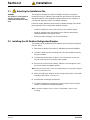
2.2 Installing the All Weather Refrigerated Sampler
The sampler can be installed using the optional anchor bracket mounting kit
(Cat. No. 8935).
1. Determine the proper site location for individual permanent installation.
2. Level the sampler using four leveling feet. Raise the sampler by turning
the feet clockwise.
3. Locate screws around base of cabinet. The front and rear screws are
used to mount the anchor brackets to the sampler.
4. Remove one screw from the cabinet. Slide the screw through the slot in
the anchor bracket and tighten halfway.
Note: Install only one bracket at a time. The sampler may become unstable if multiple
screws are removed at once.
5. With screw still loose, allow the anchor to drop down firmly in contact with
mounting surface (floor, concrete, etc.)
6. Assemble the remaining three brackets.
7. Complete installation by securing the anchor brackets to the mounting
surface as required for individual installation.
Note: A customer-supplied
7
/16 bolt or stud is recommended to ensure secure
mounting.

Page 16
Installing the Pump Tube in the Sensor Body
8837hrd.fm
Section 2
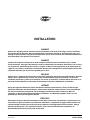
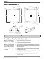
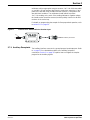
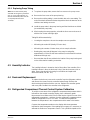
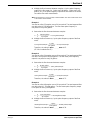
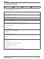
Figure 2 Anchor Bracket Mounting Kit
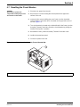
2.3 Installing the Pump Tube in the Sensor Body
Note: Do not stretch the tubing in
the sensor body, as this could affect
the sensor’s ability to detect liquid
through the pump tubing.
1. Remove the four screws on the pump cover.
2. Remove the front cover of the pump housing.
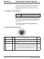
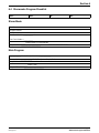
Note: Always use the proper length
of silicone tubing in the pump body.
An improper length can reduce the
life of the tubing and pump rollers.
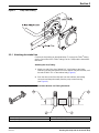
The total tube length is 33 inches
(84 cm). Refer to Figure 3 for the
correct length.
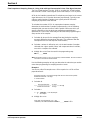
3. Remove the tubing. Locate the black dots on the tubing. The end of the
tube that extends farthest beyond the black dot attaches to the stainless
steel tubing connector.
4. Install the pump tube in the pump housing so the black dots are visible
just outside the pump body.
5. After inserting the new pump tube as shown, reinstall the front cover and
secure it with the four screws until finger tight.
6. Make sure that the tubing extends through the liquid sensor and
out of the controller.
A. AWRS Footprint with Optional Anchor Frame B. AWRS Permanent Installation Mounting Pad
1. Level Foot Mounting 2. 7/16 Bolt or Stud Recommended (not supplied) 3. 2 Places Each Side
1.7 cm
(0.66 in)
48.26 cm
(19.00 in.)
8.64 cm
(3.40 in.)
1.9 cm
(0.75 in.)
76.76 cm
(30.22 in.)
73.41 cm
(28.90 in.)
76.2 cm (30.0 in.)
70.13 cm (27.61 in.)
3.05 cm
(1.20 in.)
72.92 cm
(28.71 in.)
86.4 cm
(34.0 in.)
A
B
1
2
Minimum Pad Size
Standard Mounting
Standard Mounting w/
Optional Anchor Bracket
3

Section 2
Page 17
8837hrd.fm Installing the Pump Tube in the Sensor Body
Figure 3 Pump Tube Loading
2.3.1 Attaching the Intake Line
Connect the vinyl tubing as described below. To connect the Teflon
®
tubing,
use the Connection Kit for Teflon Tubing (Cat. No. 2186) and the instructions
that follow.
Attaching the Vinyl Tubing
1. Attach one end of the clear, flexible PVC (vinyl) tubes to the intake
strainer by pushing the tapered end of the strainer fully into the tube, until
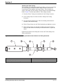
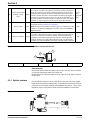
the tube is within ¼ in. of the strainer body (Figure 4).
2. Push the other end of the vinyl tube onto the stainless steel tubing
connector end that points away from the pump control housing
(see Figure 4).
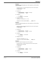
Figure 4
3
/8″ Vinyl Tube Attached to Intake Strainer and Tubing Connector
1. Vinyl tubing to controller 3. Tubing clamp (2 required)
2. Vinyl tubing to strainer or pump. 4. Stainless steel tubing connector

Page 18
Installing the Pump Tube in the Sensor Body
8837hrd.fm
Section 2
Attaching the Teflon Tubing
The connection kit contains two identical assemblies, one for the connecting
the Teflon tubing to the stainless steel Tubing Connector, the other for
connecting the Teflon tubing to the Intake Strainer. The kit contains six
clamps, two lengths of silicon tubing, and two stainless steel barbed fittings.
Refer to Figure 5 and the steps below for Teflon tubing assembly.
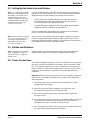
1. Place the Silicon Tubing over the wide end of the Tubing Connector.
2. Use a Tubing Clamp to secure the Silicon Tubing to the Tubing
Connector.
3. Push the stainless fitting into the Teflon-lined tubing until it abuts the
shoulder of the stainless fitting.
4. Slide a Tubing Clamp over the Teflon-lined tubing and tighten to secure.
5. Slide a Tubing Clamp over the silicone tubing, then push the silicone
tubing over the stainless steel fitting on the Intake Strainer. Tighten the
clamp.
Repeat the procedure for the fitting that connects the Teflon tubing to the
Silicon pump tubing.
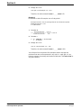
Figure 5
3
/8″ ID Teflon-lined Tubing Attached to Intake Strainer and Tubing Connector
1. Intake strainer 4. Stainless steel tubing connector
2. Tubing clamp (3 required) 5. Teflon-lined intake tubing
3. Two-inch piece of silicone tubing 6. Wide end of stainless steel tubing connector

Section 2
Page 19
8837hrd.fm Setting Up the Intake Line and Strainer
2.4 Setting Up the Intake Line and Strainer
Note: If site conditions do not permit
the intake to slope downward from
the sampler to the sample source,
disable the liquid sensors and
calibrate the sample volume using
the Timed Calibrate method when
programming the sampler (see
section 6.2 on page 57).
For each sampling location, the intake line should be as short as practical,
and be free of any sharp bends, coils, or loops. Install the intake line with a
downward slope from the sampler to the sample source because:
• This will assure the complete drainage of the intake line when it is
air-purged before and after each sample, and will help to prevent
cross-contamination of the individual samples.
• Complete drainage is important in freezing conditions because liquid
sludge that remains could freeze and plug the line.
Place the sample intake and strainer in the mainstream of the sampling
source, in an area of turbulent and well mixed flow.
Note: Vertical lift should not exceed
27 ft. If your site requires more lift,
you may purchase the Remote
Pump Option. See Parts and
Accessories on page 87.
Also, account for the vertical location of the intake. A position too near the
surface may yield excess lighter materials, while a position too near the
bottom may yield excess heavy materials. The constituents of interest must
be considered when positioning the intake strainer.
2.5 Bottles and Retainers
Note: If changing from one multiple
bottle configuration to another, it
may be necessary to change the
distributor arm.
Install the bottles in the refrigerated compartment using the appropriate
retainer and/or positioner for the bottle(s) suppled with the sampler.
2.6 Power Connections
The sampler refrigerator operates on a 115 V ac (100 and 230 V ac optional),
and has an internal circuit breaker in the Power Junction Assembly Control
Box. The controller requires 12 V dc which is supplied via an internal ac/dc
power converter. The unit may be ordered with a 3-prong ac power cord or a
conduit connection suitable for a junction box and hard-wire permanent
installation.
Important: Whenever electricity is present, there is a possibility of electrical
shock. Before connecting the sampler to an ac power source follow these
safety precautions:
1. Check the power source to make sure that it satisfies the ac power
requirements of the sampler.
2. Make sure that all electrical installations and connections are in
accordance with national and local electrical codes.
3. Before performing any maintenance, disconnect the sampler from
the power source.
4. Do not attempt to make any connection or otherwise handle the electrical
components of the sampler when connected to ac line power if the
immediate area is wet, or if hands or clothing are wet.
5. If the circuit breaker or fuse in the ac power source is tripped, determine
the cause before restoring power to the sampler.

Page 20
Flow Proportional Operation
8837hrd.fm
Section 2
6. Make sure the power circuit is grounded and protected with a Ground
Fault Interrupter (GFI).
2.7 Flow Proportional Operation
The 900 All Weather Refrigerator Sampler is equipped to receive a
momentary (minimum 25 millisecond) dry contact closure of 5 to 17 V dc from
an external flow meter to collect samples in proportion to the stream flow.
An optional interface unit is also available to accept a 4–20 mA or pulse
duration input (Cat. No. 2021). To interface with other flow meter output
signals, contact the manufacturer.
2.7.1 Contact Closure Input
The sampler is capable of accumulating 1 to 9,999 contact closures. Each
contact closure output from a flow meter represents a specific flow volume.
Some flow meters have an adjustable output, i.e. one contact closure for
every 100, 500, 1,000, 10,000 gallons of flow, etc., while others have a fixed
output. In either case, the contact closure signal will be sent more frequently
for high flow rates, and less frequently for low flow rates. The sample
frequency will increase as the flow rate increases and likewise, will decrease
as the flow rate decreases, thus taking samples in proportion to flow rate.
To connect the sampler to a flow meter, use the Signal Cable
(Cat. No. 940 or 540). To connect to another brand of flow meter, use the
Open-Ended Signal Cable (Cat. No. 941 or 541). A contact closure input
corresponds to pins A and C on the Flow Meter/Auxiliary receptacle, and
signal cable connector. The signal cable wires are white and yellow
respectively. Polarity is not important unless the same closure signal is sent to
more than one sampler.
2.7.2 Pulse Input
Note: The Sampler receives the
pulse on Pin C of the Auxiliary
Receptacle. The sampler ground
(Pin B) must be connected to the
flow meter signal ground.
The sampler can accept a 5 to 12 V dc pulse input directly from a flow meter.
The sampler is capable of accumulating from 1 to 9,999 input pulses.
This can be used in the same way as the Contact Closure input to control
sample frequency. Use cable (Cat. No. 941) to connect the sampler to a V dc
pulse source.
2.7.3 4–20 mA Input
Note: Older model 4–20 mA
interfaces require correct loop
polarity to work properly. The newer
generation interfaces are not
sensitive to loop polarity.
An optional interface unit is available (Cat. No. 2021) which converts a
4–20 mA flow meter output into 12 V dc pulses (see Figure 6). At 20 mA
(100% flow rate), the interface sends ten pulses per minute; at 4 mA (0% flow
rate), the interface sends zero pulses.
The interface has a 3 ft cable with a connector on one end, and a 10 ft cable
with two open wire leads on the other. Insert the connector into the sampler
receptacle labeled “Auxiliary”, located on the left side of the control housing.
On the 10 ft cable, the wire with clear insulation is positive (+) and the wire
with black insulation is negative (-).
Improper wiring may cause damage to the transmitter and receiver(s). Use a
multimeter to check the sampler interface for proper polarity if the sampler
does not respond to the 4–20 mA signal.Select the dc volt function on the
La pagina si sta caricando...
La pagina si sta caricando...
La pagina si sta caricando...
La pagina si sta caricando...
La pagina si sta caricando...
La pagina si sta caricando...
La pagina si sta caricando...
La pagina si sta caricando...
La pagina si sta caricando...
La pagina si sta caricando...
La pagina si sta caricando...
La pagina si sta caricando...
La pagina si sta caricando...
La pagina si sta caricando...
La pagina si sta caricando...
La pagina si sta caricando...
La pagina si sta caricando...
La pagina si sta caricando...
La pagina si sta caricando...
La pagina si sta caricando...
La pagina si sta caricando...
La pagina si sta caricando...
La pagina si sta caricando...
La pagina si sta caricando...
La pagina si sta caricando...
La pagina si sta caricando...
La pagina si sta caricando...
La pagina si sta caricando...
La pagina si sta caricando...
La pagina si sta caricando...
La pagina si sta caricando...
La pagina si sta caricando...
La pagina si sta caricando...
La pagina si sta caricando...
La pagina si sta caricando...
La pagina si sta caricando...
La pagina si sta caricando...
La pagina si sta caricando...
La pagina si sta caricando...
La pagina si sta caricando...
La pagina si sta caricando...
La pagina si sta caricando...
La pagina si sta caricando...
La pagina si sta caricando...
La pagina si sta caricando...
La pagina si sta caricando...
La pagina si sta caricando...
La pagina si sta caricando...
La pagina si sta caricando...
La pagina si sta caricando...
La pagina si sta caricando...
La pagina si sta caricando...
La pagina si sta caricando...
La pagina si sta caricando...
La pagina si sta caricando...
La pagina si sta caricando...
La pagina si sta caricando...
La pagina si sta caricando...
La pagina si sta caricando...
La pagina si sta caricando...
La pagina si sta caricando...
La pagina si sta caricando...
La pagina si sta caricando...
La pagina si sta caricando...
La pagina si sta caricando...
La pagina si sta caricando...
La pagina si sta caricando...
La pagina si sta caricando...
La pagina si sta caricando...
La pagina si sta caricando...
La pagina si sta caricando...
La pagina si sta caricando...
La pagina si sta caricando...
La pagina si sta caricando...
-
 1
1
-
 2
2
-
 3
3
-
 4
4
-
 5
5
-
 6
6
-
 7
7
-
 8
8
-
 9
9
-
 10
10
-
 11
11
-
 12
12
-
 13
13
-
 14
14
-
 15
15
-
 16
16
-
 17
17
-
 18
18
-
 19
19
-
 20
20
-
 21
21
-
 22
22
-
 23
23
-
 24
24
-
 25
25
-
 26
26
-
 27
27
-
 28
28
-
 29
29
-
 30
30
-
 31
31
-
 32
32
-
 33
33
-
 34
34
-
 35
35
-
 36
36
-
 37
37
-
 38
38
-
 39
39
-
 40
40
-
 41
41
-
 42
42
-
 43
43
-
 44
44
-
 45
45
-
 46
46
-
 47
47
-
 48
48
-
 49
49
-
 50
50
-
 51
51
-
 52
52
-
 53
53
-
 54
54
-
 55
55
-
 56
56
-
 57
57
-
 58
58
-
 59
59
-
 60
60
-
 61
61
-
 62
62
-
 63
63
-
 64
64
-
 65
65
-
 66
66
-
 67
67
-
 68
68
-
 69
69
-
 70
70
-
 71
71
-
 72
72
-
 73
73
-
 74
74
-
 75
75
-
 76
76
-
 77
77
-
 78
78
-
 79
79
-
 80
80
-
 81
81
-
 82
82
-
 83
83
-
 84
84
-
 85
85
-
 86
86
-
 87
87
-
 88
88
-
 89
89
-
 90
90
-
 91
91
-
 92
92
-
 93
93
-
 94
94


in altre lingue
- English: Hach SIGMA 900 User manual
Documenti correlati
-
 Hach 900 Manuale utente
-
 Hach AS950 Basic Installation And Maintenance
-
 Hach AS950 AWRS Basic Installation And Maintenance
-
 Hach FL1500 Basic User Manual
-
 Hach AS950 Basic Operations
-
 Hach TitraLab KF1000 Series Basic User Manual
-
 Hach BODTrak II Basic User Manual
-
 Hach 9525sc Manuale utente
-
Hach Flo-Dar Basic User Manual
-
 Hach 9525sc Manuale utente


Altri documenti
-
Omega SWS-201 Manuale del proprietario
-
Warehouse of Tiffany RL8060B Istruzioni per l'uso
-
Behringer DDM4000 Guida Rapida
-
-
Desa Tech B66D Manuale del proprietario
-
Panasonic FV-WCCS2-A Manuale utente
-
Grant Instruments XUB Digital Ultrasonic Bath Range Manuale utente
-
 Greyline Instruments PDFM 5.0 Manuale utente
-
-
Elenco 21531N Manuale del proprietario
