La pagina si sta caricando...

ART./ITEM:
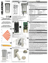
1630DT/JOLLY
1830DT/JOLLY-E
1743DT/JOLLY-T
1879DT/JOLLY-TE
La dichiarazione CE del presente articolo
è reperibile sul sito www.lince.net.
The CE declaration of this item is
available on www.lince.net website.
IT RIVELATORE DI PRESENZA A DOPPIA
TECNOLOGIA
Manuale di installazione, programmazione ed uso.
- Istruzioni originali -
EN DOUBLE TECHNOLOGY DETECTOR
Installation, programming and operating manual.
- Translation of original instructions -
MADE IN ITALY
RIVELATORI DI PRESENZA
A DOPPIA TECNOLOGIA
DOUBLE TECHNOLOGY
DETECTOR
P

LINCE ITALIA S.p.A.
2
DESCRIZIONE
I rivelatori serie Jolly uniscono in un unico dispositivo un rilevatore
a microonda ed un sensore ad infrarosso. Appositamente studiato
e realizzato per il funzionamento in ambienti difcili, garantisce
un elevato grado di immunità a fenomeni che in altri tipi di sensori
possono causare falsi allarmi.
La sequenza dei preallarmi forniti dai due sensori in esso contenuti
viene opportunamente analizzata dall’elettronica, evitando così
che fenomeni esterni come correnti d’aria, sorgenti di calore, e
disturbi di origine elettrica diano luogo ad allarmi indesiderati.
Facilmente adattabile a qualsiasi tipo di installazione sia a
parete che ad angolo, è dotato di indicatori luminosi per la
verica del corretto orientamento e regolazione di sensibilità/
portata della microonda. Una semplice impostazione dei modi
di funzionamento AND ed OR è ottenibile tramite un ponticello
estraibile (jumper).
CARATTERISTICHE TECNICHE
1630DT/JOLLY
1830DT/JOLLY-E
1743DT/JOLLY-T
1879DT/JOLLY-TE
Sensore infrarosso Doppio elemento a basso rumore
Frequenza microonda 10,525 GHz strip line
Portata 12 m
Copertura orizzontale 90° 6°
Alimentazione 8 ÷16 Vcc
Assorbimento 34 mA
Relè di allarme N.C. silenzioso 10 Ω in serie
Installazione A parete
Switch antisabotaggio N.C. contatto dedicato
Temperatura di esercizio 5° ÷ +40°C
Dimensioni (mm LxHxP) 58 x 84 x 42
Peso 70 g
INSTALLAZIONE
I rivelatori offrono prestazioni ottimali ed una elevata immunità
contro i falsi allarmi. Anche se più tollerante di altri rilevatori
tradizionali, è consigliabile praticare una buona installazione
attenendosi alle istruzioni. Individuare il punto dove ssare il
rilevatore valutando i punti di passaggio più probabili
L’altezza consigliata è di 2,2 m. Per il ssaggio agire come segue:
• Togliere la copertura facendo pressione sulla clip di aggancio
presente sul lato inferiore del rivelatore;
• passare il cavo attraverso lo snodo (fornito solo con gli art:
1630DT/JOLLY e 1743DT/JOLLY-T );
• ssare il supporto con la vite ed il tassello in dotazione ad
un’altezza da terra compresa tra i 2,10 m e i 2,30 m.
Se necessario è possibile ssare direttamente il rilevatore a
parete, o ad angolo usando le preforature previste.
COLLEGAMENTI
I collegamenti al rilevatore devono essere effettuati con cavo
schermato: collegare lo schermo alla massa della centrale
lasciandolo scollegato dalla parte del sensore. Se la distanza tra
il rilevatore e la centrale è notevole, assicurarsi che non vi sia
caduta di tensione.
Collegamenti:
N C contatto normalmente chiuso di allarme
TAMPER contatto normalmente chiuso di antisabotaggio (24
h della centrale)
+ - alimentazione 8 ÷16 Vcc
DESCRIPTION
The Jolly series detectors combines a microwave detector and
an infrared sensor in one device.
Especially designed and produced for operation in challenging
environments, it assures a high degree of immunity to phenomena
that in other types of sensors may cause false alarms.
The sequence of pre-alarms provided by the two sensors it
contains is suitably analysed by electronics, thus preventing
external phenomena such as air drafts, heat sources and
electrical disturbances from triggering unwanted alarms.
Easily adaptable to any type of wall and corner installation, it is
provided with indicator lights for checking the correct orientation
and sensitivity adjustment / microwave range.
Simple setting of AND and OR operating modes can be obtained
by means of a removable jumper.
TECHNICAL FEATURES
1630DT/JOLLY
1830DT/JOLLY-E
1743DT/JOLLY-T
1879DT/JOLLY-TE
Infrared sensor Double low noise element
Microwave frequency 10.525 GHz strip line
Range 12 m
Horizontal coverage 90° 6°
Power supply 8 ÷16 Vdc
Absorption 34 mA
Alarm relay N.C. silent 10 Ω in series
Installation Wall mountable
Anti-tamper switch N.C. dedicated contact
Operating temperature 5° ÷ +40°C
Dimensions (WxHxD mm) 58 x 84 x 42
Weight 70 g
INSTALLATION
The detectors offers optimal performance and high false alarm
immunity. Although it is more tolerant than other conventional
detectors, it is advisable to install it carefully, following the
instructions. Locate the point where to secure the detector after
identifying the most likely waypoints.
The recommended height is 2.2 m. For fastening, act as follows:
• remove the cover by pressing the attachment clip on the
underside of the detector;
• run the cable through the bracket (supplied only with , items:
1630DT/JOLLY and 1743DT/JOLLY-T),
• secure the support with the supplied screw and plug at a
height between 2.10 m and 2.30 m from ground.
If necessary, you can attach the detector directly to the wall or in
the corner using the predrilled holes provided.
CONNECTIONS
Connections with detectors must be performed with shielded
cable: Connect the shield to the control panel earth, leaving
it unconnected on the detector side. If the distance between
detector and control panel is signicant, ensure there is no
voltage drop.
Connections:
N C contatto normalmente chiuso di allarme
TAMPER Normally closed, antisabotage contact (24 h of the
control panel)
+ - Power supply 8 ÷16 Vdc

3
LINCE ITALIA S.p.A.
PROGRAMMAZIONE
Tramite il ponticello slabile (jumper) è possibile programmare il
rivelatore per due distinti modi di funzionamento:
JUMPER INSERITO = AND: la commutazione del relè avviene
solo se entrambi i sensori rilevano contemporaneamente
un’intrusione.
JUMPER SFILATO = OR: l’allarme viene inviato anche se a
rilevare è uno solo dei due sensori.
Nota: la funzione OR garantisce una maggiore protezione ma
aumenta notevolmente la possibilità di falsi allarmi, soprattutto
in ambienti “difcili”; in ogni caso occorre regolare il trimmer
relativo alla portata del sensore (sens MW) non oltre la zona da
proteggere.
FUNZIONE DEI LED
LED giallo: lampeggiante, la microonda sta rilevando del
movimento nell’ambiente
LED verde: acceso sso, il sensore infrarosso ha rilevato una
presenza
LED rosso: acceso sso, condizione di allarme.
Tramite il jumper “C” è possibile abilitare (jumper inserito)
l’accensione dei LED o disabilitarla (jumper disinserito).
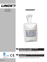
COPERTURA
La copertura dell’area protetta è determinata dall’effetto
combinato dei due sensori infrarosso e microonda.
La microonda ha un angolo di copertura di 90° sul piano
orizzontale mentre il sensore infrarosso, all’interno della stessa
area, dispone di 24 fasci su 4 livelli, ognuno dei quali genera
un segnale differenziale. Nella gura sono riportati sia i fasci del
sensore infrarosso sia, mediante linea continua, l’area coperta
dalla microonda.
PROVA DI COPERTURA
Eseguire nell’ambiente in cui è installato il rivelatore una prova di
portata aumentando gradualmente la sensibilità della microonda
tramite il trimmer (range) al ne di ottenere l’accensione del LED
giallo no al limite della zona da proteggere e non oltre.
N.B.: La prova di copertura deve essere effettuata con il rivelatore
perfettamente chiuso.
PROGRAMMING
Through the removable jumper, the detector can be programmed
for two distinct modes:
JUMPER CONNECTED = AND: relay switching takes place only
if both sensors simultaneously detect an intrusion.
JUMPER REMOVED = OR: the alarm is sent even if only one of
the two sensors detects.
Note: The OR function ensures increased protection, but
signicantly increases the possibility of false alarms, especially
in “difcult” environments; in any case, when setting the sensor
range (sens MW) via a trimmer, do not extend range beyond the
area to be protected.
LED FUNCTION
Yellow LED: Flashing, the microwave is detecting motion in the
room
Green LED: Steady on, the infrared sensor has detected a
presence
Red LED: Steady on, alarm condition.
Through the jumper “C” it is possible to enable (jumper inserted)
the lighting of the LEDs or disable it (jumper off).
COVERAGE
The coverage of the protected area is determined by the
combined effect of the two infrared and microwave sensors.
The microwave has a coverage angle of 90° on a horizontal
plane while the infrared sensor, within the same area, has 24
4-level bundles, each of which generates a differential signal.
The gure shows both the infrared sensor beams and, by a
continuous line, the area covered by the microwave.
TEST COVERAGE
In the environment where the detector has been installed, perform
a range test gradually increasing the microwave sensitivity via the
trimmer (range) so as to switch on the yellow LED lights up to the
limit of the area to be protected and not beyond.
N.B.: The test coverage must be performed with the detector
properly closed.

001530/00373AC REV1
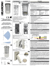
Fig. 1
Fig. 2
B
A
B
A
C
C
LINCE ITALIA S.p.A
Via Variante di Cancelliera, snc
00072 ARICCIA (Roma)
Tel. +39 06 9301801
Fax +39 06 930180232
info@lince.net
www.lince.net
VISTA IN PIANTA
VISTA IN PIANTA
VISTA LATERALE
VISTA LATERALE
Graco di copertura
Il graco di copertura indica la posizione dei fasci dell’IR. La
copertura della microonda è di 90°.
1630DT/JOLLY
1830DT/JOLLY-E
1743DT/JOLLY-T
1879DT/JOLLY-TE
PLAN VIEW
PLAN VIEW
SIDE VIEW
SIDE VIEW
A Trimmer della portata mi-
croonda
B Jumper per la selezione
della funzione AND o OR
Di fabbrica Jumper inseri-
to ( AND )
C Jumper per l’esclusione
dei LED
A Microwave range trimmer.
B Jumper for selecting the
AND or OR function Fac-
tory-set Connected jum-
per (AND).
C Jumper for LED exclusion
Covered area pattern
The range chart indicates the position of the IR beams. The
microwave coverage is 90°.
A Trimmer della portata mi-
croonda
B Jumper per la selezione
della funzione AND o OR
Di fabbrica Jumper inseri-
to ( AND )
C Jumper per l’esclusione
dei LED
A Microwave range trimmer.
B Jumper for selecting the
AND or OR function Fac-
tory-set Connected jum-
per (AND).
C Jumper for LED exclusion
1/4