
Русский
RU
F
rança
i
s
FR
E
ng
li
s
h
EN
I
ta
li
an
o
IT
119RU01
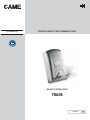
MANUALE D’INSTALLAZIONE
TRA08
SISTEMA COMPLETO PER COMANDI RADIO

Pag.
2
2 - Codice manuale
119RU01IT
119R U01IT - ver.
2
2 - 03/2016 - © Came S.p.A. - I contenuti del manuale sono da ritenersi suscettibili di modifica in qualsiasi momento senza obbligo di preavviso.
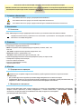
2.1 Destinazione d’uso
1 Legenda simboli
Questo simbolo indica parti da leggere con attenzione.
Questo simbolo indica parti riguardanti la sicurezza.
Questo simbolo indica cosa comunicare all’utente.
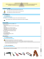
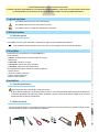
Il kit TRA08 è adatto a comandare, solo via radio, fino a 4 automazioni distinte.
Ogni installazione e uso difformi da quanto indicato nel seguente manuale sono da considerarsi vietate.
Progettato e costruito interamente dalla CAME S.p.A.
Il kit comprende:
- n° 1 RBE42: ricevitore radio quadricanale per esterni a 230 V.
Relè da 5 A.
- n° 2 TOP-434EE: trasmettitori quadricanale;
- n° 1 TOP-A433N: antenna con staffa di fissaggio;
- n° 1 TOP-RG58: cavo coassiale per antenna (5 m).
Un radiocomando per controllare quattro impianti:
- attivare l’allarme;
- accendere le luci esterne;
- aprire l’impianto di irrigazione;
- chiudere le tapparelle.
“IMPORTANTI ISTRUZIONI DI SICUREZZA PER L’INSTALLAZIONE”
“ATTENZIONE: L’INSTALLAZIONE NON CORRETTA PUÓ CAUSARE GRAVI DANNI, SEGUIRE TUTTE LE ISTRUZIONI DI INSTALLAZIONE”
“IL PRESENTE MANUALE É DESTINATO ESCLUSIVAMENTE A INSTALLATORI PROFESSIONALI O A PERSONE COMPETENTI”
2 Destinazione d’uso
4 Descrizione
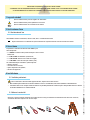
5.1 Verifiche preliminari
5.2 Attrezzi e materiali
Prima di intervenire all’interno dell’apparecchiatura, togliere la tensione di linea.
• Non installare più ricevitori ad una distanza inferiore a 4-5 m l’uno dall’altro, onde evitare anomalie di funzionamento.
• Il ricevitore deve essere sempre munito di antenna. Se possibile posizionare l’antenna il più in alto possibile da terra e lontana
da strutture metalliche e in cemento armato.
Assicurarsi di avere tutti gli strumenti ed il materiale necessario, per effettuare l’installazione nella massima sicurezza,
secondo le normative vigenti. Ecco alcuni esempi.
5 Installazione

CAME
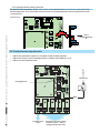
75 mm
87 mm
115 mm
225 mm
180 mm
5
6
7
8
9
4
3
2
1
Pag.
3
3 - Codice manuale
119RU01IT
119R U01IT - ver.
2
2 - 03/2016 - © Came S.p.A. - I contenuti del manuale sono da ritenersi suscettibili di modifica in qualsiasi momento senza obbligo di preavviso.
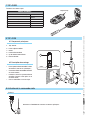
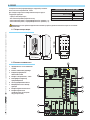
DATI TECNICI
Alimentazione 230 V A.C.
Classe di isolamento
Materiale ABS
Grado di protezione IP54
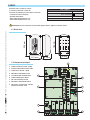
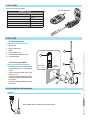
6.1 Dimensioni
Ricevitore radio a 4 canali da esterno.
La scheda va alimentata a 230 V AC.
Le funzioni selezionabili per ogni singola uscita sono:
- comando ad azione mantenuta;
- bistabile (interruttore);
- monostabile temporizzato fisso 3”;
- monostabile temporizzato fisso 5’.
Attenzione! Prima di intervenire all’interno dell’apparecchiatura, togliere la tensione di linea.
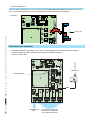
6 RBE42
6.2 Componenti principali
1. Fusibile centralina (315 mA - rapido)
2. Pulsanti memorizzazione codice radio
3. Fusibile linea (125 mA - rapido)
4. Morsettiera alimentazione 230 V
5. Led segnalazione memorizzazione
6. Scheda radiofrequenza AF43S
7. Dip-switch selezione funzioni
8. Morsettiera collegamento antenna
9. Morsettiere collegamento impianti
(portata max dei relè: 10 A)

5
1
2
43
6
3
Pag.
4
4 - Codice manuale
119RU01IT
119R U01IT - ver.
2
2 - 03/2016 - © Came S.p.A. - I contenuti del manuale sono da ritenersi suscettibili di modifica in qualsiasi momento senza obbligo di preavviso.
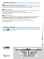
Trasmettitore canale multiutenza
DATI TECNICI
Frequenza AM 433.92 MHz
Batterie n° 2 CR2016 - 3 V DC
Lithium
Assorbimento in trasmissione 12 mA
Portata 50 ÷ 150 m
Combinazione codice 4096
Peso 16 g
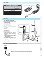
8 TOP-433N
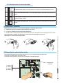
8.1 Componenti principali
1. Stelo antenna
2. Parte superiore contenitore
3. Circuito
4. Parte inferiore contenitore
5. Viti fi ssaggio antenna/sta a
6. Sta a di fi ssaggio
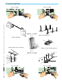
8.2 Descrizione del montaggio
• Fissare la parte inferiore del contenitore
alla sta a di fi ssaggio, con le apposite
viti;
• collegare il cavo coassiale RG58 al
morsetto del circuito antenna;
• inserire il circuito sulla parte inferiore del
contenitore tramite l’apposito foro posto
sul circuito stesso;
• incastrare i due contenitori tra di loro e
avvitare lo stelo.
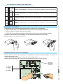
Collegare il cavo RG58 dell’antenna agli appositi morsetti.
9 Attivazione del comando radio
Antenna
Led rosso di segnalazione
Calza Cavo
7 TOP-434EE

AF43S
RG58
TOP-A433N
Pag.
5
5 - Codice manuale
119RU01IT
119R U01IT - ver.
2
2 - 03/2016 - © Came S.p.A. - I contenuti del manuale sono da ritenersi suscettibili di modifica in qualsiasi momento senza obbligo di preavviso.
Scheda di radiofrequenza
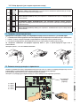
Innestare la scheda di radiofrequenza sulla scheda elettronica DOPO AVER TOLTO LA TENSIONE (o scollegato le batterie).
N.B.: La scheda elettronica riconosce la scheda di radiofrequenza solo quando viene alimentata.
Scheda base
Scheda “AF”
10 Collegamenti elettrici
• Collegare i dispositivi da comandare sulle 4 uscite, selezionando per ognuna la funzione desiderata;
• connettere l’antenna sul relativo morsetto con cavo RG58 (vedi pag. 4);
• alimentare la scheda con una tensiona di linea di 230 V.
selezione funzioni *
alimentazione
230 V A.C.
ai dispositivi da comandare
(potenza max 250 V AC, con
carico non induttivo)

1 2 3
/.
/&&
/.
/&&
/.
/&&
/.
/&&
Pag.
6
6 - Codice manuale
119RU01IT
119R U01IT - ver.
2
2 - 03/2016 - © Came S.p.A. - I contenuti del manuale sono da ritenersi suscettibili di modifica in qualsiasi momento senza obbligo di preavviso.
Funzione “azione mantenuta”: l’azione del relè dura fino a quando si tiene premuto il pulsante del
trasmettitore.
Monostabile temporizzato fisso 3”: dopo aver rilasciato il pulsante del trasmettitore l’azione del relè
dura 3 secondi.
Bistabile (interruttore): premendo ripetutamente il pulsante del trasmettitore si attiva e disattiva il
relè continuamente come se si agisse su un interruttore.
Monostabile temporizzato fisso 5’: dopo aver premuto il pulsante del trasmettitore l’azione del relè
dura 5 minuti.
* 10.1 Selezione funzioni (per ogni singola uscita)
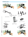
11 Duplicare un trasmettitore
La duplicazione deve essere fatta perchè i trasmettitori sono fabbricati ciascuno con un codice diverso.
1. Premere assieme i primi 2 tasti fi no a quando il led lampeggia più velocemente;
2. premere ora il tasto da attivare (il Led si accende);
3. entro 10”, appogiare alla sua parte posteriore il trasmettitore attivo e premere per qualche istante il tasto di duplicare.
A memorizzazione avvenuta, il LED lampeggerà per 3 volte e il trasmettitore sarà pronto all’uso.
Ripetere i punti 1, 2 e 3 per i tasti rimanenti.
12 Memorizzazione codice sul ricevitore
Tenere premuto un tasto di memorizzazione e, quando il led di segnalazione lampeggia, premere il tasto del trasmettitore per
inviare il codice.
Il led rimarrà acceso a segnalare l’avvenuta memorizzazione.
Eseguire la stessa procedura per ogni uscita (vedi anche esempi alle pagine successive).
1 => OUT1
2 => OUT2
3 => OUT3
4 => OUT4
LED di segnalazione
codice radio

P1 => 1 => OUT1 P2 => 2 => OUT2
P3 => 3 => OUT3 P4 => 4 => OUT4
CAME
CAME
P4
P3
P1
P2
P1
P2
P3 P4
Pag.
7
7 - Codice manuale
119RU01IT
119R U01IT - ver.
2
2 - 03/2016 - © Came S.p.A. - I contenuti del manuale sono da ritenersi suscettibili di modifica in qualsiasi momento senza obbligo di preavviso.
Sbarra condominio
Luci viale temporizzate
Luci scale ingresso temporizzate
Portone sezionale accesso zona garage
13 Esempio di applicazione

www. came.com
www. came.com
CAME S.p.A.
CAME S.p.A.
Via Martiri Della Libertà, 15 Via Cornia, 1/b - 1/c
31030
Dosson di Casier
Dosson di Casier
Treviso
Treviso - Italy
33079
Sesto al Reghena
Sesto al Reghena
Pordenone
Pordenone - Italy
(+39) 0422 4940
(+39) 0422 4941
(+39) 0434 698111
(+39) 0434 698434
Italiano
Italiano - Codice manuale
119RU01IT
119R U01IT - ver.
2
2 - 03/2016 - © Came S.p.A.
I contenuti del manuale sono da ritenersi suscettibili di modifica in qualsiasi momento senza obbligo di preavviso.
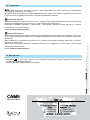
14 Dismissione e smaltimento
15 Dichiarazione di conformità
Dichiarazione - Came S.p.A. dichiara che questo dispositivo è conforme ai requisiti essenziali e alle altre disposizioni
pertinenti stabilite dalla direttiva 1999/5/CE.
Originale su richiesta.
CAME S.p.A. implementa all’interno dei propri stabilimenti un Sistema di Gestione Ambientale certificato e conforme
alla norma UNI EN ISO 14001 a garanzia del rispetto e della tutela dell’ambiente.
Vi chiediamo di continuare l’opera di tutela dell’ambiente, che CAME considera uno dei fondamenti di sviluppo delle proprie
strategie operative e di mercato, semplicemente osservando brevi indicazioni in materia di smaltimento:
SMALTIMENTO DELL’IMBALLO
I componenti dell’imballo (cartone, plastiche etc.) sono assimilabili ai rifiuti solidi urbani e possono essere smaltiti senza alcuna
difficoltà, semplicemente effettuando la raccolta differenziata per il riciclaggio.
Prima di procedere è sempre opportuno verificare le normative specifiche vigenti nel luogo d’installazione.
NON DISPERDERE NELL’AMBIENTE!
SMALTIMENTO DEL PRODOTTO
I nostri prodotti sono realizzati con materiali diversi. La maggior parte di essi (alluminio, plastica, ferro, cavi elettrici) è assimilabile
ai rifiuti solidi e urbani. Possono essere riciclati attraverso la raccolta e lo smaltimento differenziato nei centri autorizzati.
Altri componenti (schede elettroniche, batterie dei radiocomandi etc.) possono invece contenere sostanze inquinanti.
Vanno quindi rimossi e consegnati a ditte autorizzate al recupero e allo smaltimento degli stessi.
Prima di procedere è sempre opportuno verificare le normative specifiche vigenti nel luogo di smaltimento.
NON DISPERDERE NELL’AMBIENTE!

COMPLETE SYTEM FOR RADIO COMMANDS
INSTALLATION MANUAL
TRA08
E
ng
li
s
h
EN
119RU01EN

p.
2
2 - Manual code
119R
119R
U01
U01
EN
EN v.
2
2- 03/2016 - © Came S.p.A. The contents of this manual may be revised at any time, and without notice.
2.1 Intended use
Legend of symbols
This symbol shows parts which must be read with care.
This symbol means the parts which describe safety issues.
This symbol tells you what to tell the end-user.
The TRA08 kit is for commanding, only by radio, up to four different operators.
Any installation and use other than that specified in this manual is forbidden.
Engineered and built entirely by CAME S.p.A.
The kit comprises:
- 1 RBE42: 230 V outdoor four-channel radio receiverV.
5 A relay.
- 2 TOP-434EE : four-channel transmitters;
- 1 TOP-A433N: antenna with fastening bracket;
- 1 TOP-RG58: co-axial antenna cable (5 m).
One radio command to control four systems:
- arm the alarm;
- turn on outdoor lights;
- turn on the lawn sprinkler system;
- close the shutters.
"IMPORTANT INSTALLATION SAFETY INSTRUCTIONS"
“WARNING: IMPROPER INSTALLATION MAY RESULT IN SERIOUS HARM. PLEASE FOLLOW ALL INSTALLATION INSTRUCTIONS”
“THIS MANUAL IS INTENDED ONLY FOR PROFESSIONAL INSTALLERS OR OTHER COMPETENT INDIVIDUALS”
2.1 Intended use
4 Description
5.1 Preliminary checks
5.2 Tools and equipment
Cut off the main power before acting inside the equipment.
• Do not install multiple receivers at less than 4-5 m from each other, to prevent functioning anomalies
• The receiver must always be fi tted with an antenna. Possibly place the antenna as high as possible from the ground and far from
any metal and reinforced concrete structures.
Make sure you have all the tools and materials needed to carry out the installation in total safety and in accordance with
current regulations. Here are some examples.
5 Installation

CAME
75 mm
87 mm
115 mm
225 mm
180 mm
5
6
7
8
9
4
3
2
1
p.
3
3 - Manual code
119R
119R
U01EN
U01EN v.
2
2- 03/2016 - © Came S.p.A. The contents of this manual may be revised at any time, and without notice.
TECHNICAL DATA
Power supply 230V A.C.
Insulation class
Material ABS
Protection rating IP54
6.1 Dimensions
4-channel outdoor radio receiver.
The board is powered by 230 V AC.
For each single output you can select the following features :
- maintained action command;
- bistable (switch);
- fixed 3 second timed monostable”;
- fixed 5 minute timed monostable’.
Warning! Cut off the main power before acting inside the equipment.
6 RBE42
6.2 Main components
1. Control unit fuse (315 mA - quick)
2. Buttons to memorise radio code
3. Line fuse (125 mA - quick)
4. 230 V power supply terminals
5. Memorisation underway LED
6. AF43S radio-frequency card
7. Functions selection Dip switch
8. Antenna connection terminals
9. Systems connection terminals (relay
rated max: 10A)

5
1
2
43
6
3
p.
4
4 - Manual code
119R
119R
U01
U01
EN
EN v.
2
2- 03/2016 - © Came S.p.A. The contents of this manual may be revised at any time, and without notice.
7 TOP-434EE
Multi-user channel transmitter
TECHNICAL DATA
Frequency AM 433.92 MHz
Batteries two CR2016 - 3 V DC
Lithium
Power draw when transmitting 12 mA
Effective to 50 ÷ 150 m
Code combination 4096
Weight 16 G
8 TOP-433N
8.1 Main components
1. Antenna rod
2. Upper container part
3. Circuit
4. Lower container part
5. Antenna/ bracket fastening screws
6. Fastening bracket
8.2 Mounting description
• Fasten the lower part of the container to
the anchoring bracket - use the supplied
screws;
• connect the RG58 coaxial cable to the
antenna circuit;
• insert the circuit into the lower part of the
container trough the apposite hole on the
circuit itself;
• fi t the two containers together and screw
in the shaft.
Connect RG58 antenna cable to the apposite terminals.
9 Activating the radio command
Antenna
Red LED signal light
Cable grip Cable

AF43S
RG58
TOP-A433N
p.
5
5 - Manual code
119R
119R
U01EN
U01EN v.
2
2- 03/2016 - © Came S.p.A. The contents of this manual may be revised at any time, and without notice.
Radio frequency card
Plug in the radio-frequency card onto the electronic board AFTER CUTTING OFF THE MAIN POWER SUPPLY (or disconnecting
the emergency batteries).
N.B.: The electronic card recognises the radio-frequency card only when it is powered up.
Basic Card
AF card
10 Electrical connections
• Connect the devices to command onto the 4 outputs, selecting the feature you want for each one;
• connect the antenna onto the relative terminal with the RG58 cable (see p. 4);
• power the card with a 230 V line
selecting functions *
Power supply
230 V A.C.
to the devices to be comman-
ded (max. power 250 V AC, with
inductive load)

1 2 3
/.
/&&
/.
/&&
/.
/&&
/.
/&&
p.
6
6 - Manual code
119R
119R
U01
U01
EN
EN v.
2
2- 03/2016 - © Came S.p.A. The contents of this manual may be revised at any time, and without notice.
"Maintained action" feature : the relay action lasts as long as the transmitter button is pressed .
Fixed 3 second timed monostable”: once the transmitter button is released the relay action lasts 3
seconds.
Bistable (switch): repeatedly pressing the transmitter button will turn on and off the relay conti-
nuously as if it were a switch.
Fixed 5 minute timed monostable: once the transmitter button is released the relay action lasts 5
minutes.
* 10.1 Selecting functions (for each single output)
11 Duplicating a transmitter
Duplication must be done because each of the transmitters is made with different codes.
1. Simultaneously press the two buttons until the LED fl ashes more quickly;
2. 2 - now press the button you wish to activate (the LED lights up);
3. with 10 seconds, rest the active transmitter against it back part and press the button that needs duplicating for a few seconds.
Once memorisation is complete, the LED will flash 3 times and the transmitter will be ready for use.
Repeat points 1, 2 and 3 for the remaining buttons.
12 Memorising the code onto the receiver
Keep memorisation button pressed until the LED flashes, press the transmitter button to send the code.
The LED will stay ON to confirm memorisation is OK.
Perform the same procedure for each exit (also see examples on the following pages).
1 => OUT1
2 => OUT2
3 => OUT3
4 => OUT4
LED signal light
radio code

P1 => 1 => OUT1 P2 => 2 => OUT2
P3 => 3 => OUT3 P4 => 4 => OUT4
CAME
CAME
P4
P3
P1
P2
P1
P2
P3 P4
p.
7
7 - Manual code
119R
119R
U01EN
U01EN v.
2
2- 03/2016 - © Came S.p.A. The contents of this manual may be revised at any time, and without notice.
Apartment block barrier
Timed walkway lights
Timed entrance-stairs lights
Sectional door to garage zone
13 Application example

www. came.com
www. came.com
CAME S.p.A.
CAME S.p.A.
Via Martiri Della Libertà, 15 Via Cornia, 1/b - 1/c
31030
Dosson di Casier
Dosson di Casier
Treviso
Treviso - Italy
33079
Sesto al Reghena
Sesto al Reghena
Pordenone
Pordenone - Italy
(+39) 0422 4940
(+39) 0422 4941
(+39) 0434 698111
(+39) 0434 698434
English
English - Manual code
11
11
9RU01EN
9RU01EN v.
2
2 - 03/2016 - © Came S.p.A.
The contents of this manual may be revised at any time, and without notice.
14 Dismantling and disposal
15 Compliance statement
Declaration - Came S.p.A. declares that this device conforms with the essential requirements and other pertinent provisions
established by directive 1999/5/CE
An original copy is available on request.
CAME S.p.A. employs a UNI EN ISO 14001 certified and compliant environmental protection system at its plants, to
ensure that environmental safeguarding.
We ask you to keep protecting the environment, as CAME deems it to be one of the fundamental points of its market operations
strategies, by simply following these brief guidelines when disposing:
DISPOSING THE PACKING MATERIALS
The packing components (cardboard, plastic, etc.) are solid urban waste and may be disposed of without any particular
difficulty, by simply separating them so that they can be recycled.
Before actions it is always advisable to check the pertinent legislation where installation will take place.
DO NOT DISPOSE OF IN NATURE!
DISPOSING OF THE PRODUCT
Our products are made using different types of materials. The majority of them (aluminium, plastic, iron, electric cables) can be
considered to be solid urban waste. They may be recycled at authorised firms.
Other components (electrical circuit board, remote control batteries etc.) may contain hazardous waste.
They must, thus, be removed and turned in to licensed firms for their disposal.
Before acting always check the local laws on the matter.
DO NOT DISPOSE OF IN NATURE!

SYSTÈME COMPLET POUR COMMANDES RADIO
MANUEL D'INSTALLATION
TRA08
F
rança
is
FR
119RU01FR

Page
2
2 - Code manuel
119
119
RU01FR
RU01FR - vers.
2
2- 03/2016 - © Came S.p.A. - Le contenu du manuel est susceptible de subir des modifications à tout moment et sans aucun préavis.
2.1 Utilisation prévue
1 Légende symboles
Ce symbole indique des parties à lire attentivement.
Ce symbole indique des parties concernant la sécurité.
Ce symbole indique ce qui doit être communiqué à l'utilisateur.
Le kit TRA08 a été conçu pour commander, uniquement via radio, jusqu'à 4 automatismes différents.
Toute installation et toute utilisation autres que celles qui sont indiquées dans ce manuel sont interdites.
Entièrement conçu et fabriqué par la société CAME S.p.A.
Le kit comprend :
- 1 RBE42 : récepteur radio 4 canaux pour extérieurs à 230 V.
Relais de 5 A.
- 2 TOP-434EE : émetteurs 4 canaux ;
- 1 TOP-A433N : antenne avec étrier de fixation.
- 1 TOP-RG58 : câble coaxial pour antenne (5 m).
Une radiocommande pour le contrôle des quatre installations :
- activer l’alarme ;
- allumer les lumières extérieures ;
- ouvrir le système d'arrosage ;
- fermer les volets roulants.
« INSTRUCTIONS IMPORTANTES DE SÉCURITÉ POUR L'INSTALLATION »
« ATTENTION : UNE INSTALLATION INCORRECTE PEUT PROVOQUER DE GRAVES DOMMAGES, SUIVRE TOUTES LES INSTRUCTIONS D'INSTALLATION »
« LE PRÉSENT MANUEL N'EST DESTINÉ QU'À DES INSTALLATEURS PROFESSIONNELS OU À DES PERSONNES COMPÉTENTES »
2 Utilisation prévue
4 Description
5.1 Contrôles préliminaires
5.2 Outils et matériel
Avant d'intervenir dans l'appareillage, mettre hors tension.
• Ne pas installer les récepteurs à une distance inférieure à 4-5 m l’un de l'autre afi n d'éviter toute anomalie de fonctionnement.
• Le récepteur doit toujours être doté d'une antenne. Positionner l'antenne le plus haut possible par rapport au sol et à l'écart
de toute structure en métal ou en béton armé.
S'assurer de disposer de tous les instruments et de tout le matériel nécessaire pour effectuer l'installation en toute sécurité
et conformément aux normes en vigueur. Quelques exemples :
5 Installation

CAME
75 mm
87 mm
115 mm
225 mm
180 mm
5
6
7
8
9
4
3
2
1
Page
3
3 - Code manuel
119
119
RU01FR
RU01FR - vers.
2
2- 03/2016 - © Came S.p.A. - Le contenu du manuel est susceptible de subir des modifications à tout moment et sans aucun préavis.
DONNÉES TECHNIQUES
Alimentation 230 V C.A.
Classe d'isolation
Matériel ABS
Degré de protection IP54
6.1 Dimensions
Récepteur radio 4 canaux d'extérieur.
La carte doit être alimentée en 230 V CA.
Les fonctions pouvant être sélectionnées pour chaque sortie sont :
- commande à action maintenue ;
- bistable (interrupteur) ;
- monostable temporisé fixe 3” ;
- monostable temporisé fixe 5'.
Attention ! Avant d'intervenir dans l'appareillage, mettre hors tension.
6 RBE42
6.2 Composants principaux
1. Fusible centrale (315 mA - rapide)
2. Bouton de mémorisation code radio
3. Fusible ligne (125 mA - rapide)
4. Barrette d'alimentation 230 V
5. Voyant signalisation mémorisation
6. Carte radiofréquence AF43S
7. Commutateurs DIP sélection
fonctions
8. Barrette de connexion antenne
9. Barrettes de connexion installations
(portée max. des relais : 10 A)

5
1
2
43
6
3
Page
4
4 - Code manuel
119
119
RU01FR
RU01FR - vers.
2
2- 03/2016 - © Came S.p.A. - Le contenu du manuel est susceptible de subir des modifications à tout moment et sans aucun préavis.
7 TOP-434EE
Émetteur canal multi-usages
DONNÉES TECHNIQUES
Fréquence AM 433,92 MHz
Batteries 2 CR2016 - 3 V CC
Lithium
Absorption en transmission : 12 mA
Portée 50 ÷ 150 m
Combinaison code 4096
Poids 16 g
8 TOP-433N
8.1 Composants principaux
1. Tige antenne
2. Partie supérieure boîtier
3. Circuit
4. Partie inférieure boîtier
5. Vis de fi xation antenne/étrier
6. Étrier de fi xation
8.2 Description du montage
• Fixer la partie inférieure du boîtier à l'étrier
de fi xation à l'aide des vis spécifi ques ;
• connecter le câble coaxial RG58 à la borne
du circuit antenne ;
• installer le circuit sur la partie inférieure
du boîtier à travers le trou prévu sur le
circuit lui-même ;
• unir les deux boîtiers et visser la tige.
Connecter le câble RG58 de l’antenne aux bornes spécifiques.
9 Activation de la commande radio
Antenne
Voyant rouge.
Gaine Câble
La pagina si sta caricando...
La pagina si sta caricando...
La pagina si sta caricando...
La pagina si sta caricando...
La pagina si sta caricando...
La pagina si sta caricando...
La pagina si sta caricando...
La pagina si sta caricando...
La pagina si sta caricando...
La pagina si sta caricando...
La pagina si sta caricando...
La pagina si sta caricando...
-
 1
1
-
 2
2
-
 3
3
-
 4
4
-
 5
5
-
 6
6
-
 7
7
-
 8
8
-
 9
9
-
 10
10
-
 11
11
-
 12
12
-
 13
13
-
 14
14
-
 15
15
-
 16
16
-
 17
17
-
 18
18
-
 19
19
-
 20
20
-
 21
21
-
 22
22
-
 23
23
-
 24
24
-
 25
25
-
 26
26
-
 27
27
-
 28
28
-
 29
29
-
 30
30
-
 31
31
-
 32
32


in altre lingue
- français: CAME TRA08 Guide d'installation
Documenti correlati
-
CAME TRA08 Manuale del proprietario
-
-
-
-
-
-
-
-
-
