
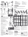
• A DIP switch per l’allineamento della barriera superiore.
• B DIP switch per l’allineamento della barriera inferiore.
• ALARM (rosso) si accende in caso di segnale di allarme.
• I LED 1-10 indicano il livello dell’allineamento delle barriere.
• A.POWER (verde) si accende quando la barriera in alto è alimentata.
• B.POWER (verde) si accende quando la barriera in basso è alimentata.
• A DIP switch for the upper beam alignment.
• B DIP switch for the lower beam alignment.
• ALARM (red) is ON when the beam senses alarm conditions.
• LEDs 1-10 is ON indicate the level of the beam alignment.
• A.POWER (green) is ON when the upper beam is powered.
• B.POWER (green) is ON when the lower beam is powered.
GENERAL VIEW
INSTALLATION
1. Svitare la vite di fissaggio del coperchio e rimuoverlo.
2. Far passare i cavi attraverso il foro apposito.
3. Montare il sensore.
4. Collegare i cavi ai terminali.
5. Allineare i sensori.
6. Chiudere il sensore.
Montaggio a muro
3a-1. Rompere il fondo dei fori per il fissaggio a muro.
3a-2. Utilizzare viti con lunghezza minima di 15mm
Montaggio su palo
3b-1. Forare il palo e fare passare i cavi attraverso il foro fatto.
3b-2. Rompere il fondo dei fori per il fissaggio su palo.
3b-3. Fissare il sensore al palo usando le staffe fornite.
VISTA GENERALE
INSTALLAZIONE
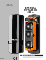
BARRIERA OTTICA
A QUADRUPLO RAGGIO
QUAD PHOTOELECTRIC
BEAM DETECTOR
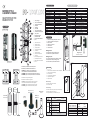
1) Mount screw location
2) Viewfinder location
3) Alignment DIP switch
4) Tamper protection
5) Connection terminal board
6) ALARM LED
7) Voltage-tester entry
8) Response time adjustment
9) Wire entry
10) Horizontal adjustment trimmer
11) Vertical adjustment screw
12) Beam alignment-level indicators
13) Lenss
Interno e coperchio
Interior and cover
1) Foro per fissaggio
2) Foro per inserimento del mirino
3) DIP switch per l’allineamento
4) Antiapertura
5) Morsettiera
6) LED ALARM
7) Foro per test livello segnale
8) Calibrazione del tempo di risposta
9) Foro passacavi
10) Calibrazione orizzontale
11) Calibrazione verticale
12) Indicatori LED dell’allineamento
13) Lenti
3b-1
0.5
0.75
1.25
2.0
0.8
1.0
1.2
1.6
Cavo Cable
Sezione (mm²) Diametro (mm)
Section (mm²)
300
400
700
1000
Lunghezza cavi
(mm)
Wiring distance
(mm)
DC 12V
600
800
1400
2000
DC 24V
Diameter (mm)
SPECIFICHE TECNICHE
Tensione di alimentazione
Tensione nominale
Corrente assorbita (max)
Temperatura di funzionamento
Umidità ambientale
Copertura all’esterno
Copertura all’interno
Tipologia raggi
Tempo di risposta
Tempo di allarme
Uscita d’allarme relè
Uscita antimanomissione
Metodo d’installazione
Angoli per il direzionamento
Grado IP
Peso
Aspetto
12 ÷ 24 Vdc
13,8 Vdc
100 mA 105 mA
-25 ÷ +55 °C
5 ÷ 95 %
100 200
300 600
Quadruplo raggio a impulsi infrarossi
50 ÷ 700 msec (selezionabile)
2 sec (± 1) nominale
N.C. o N.O., 30 Vdc, 500 mA max.
N.C., 30 Vdc, 500 mA max.
Montaggio a muro o su palo
Orizzontale 180° (± 90°), verticale 20° (± 10°)
IP54
3100 g (ricevitore + trasmettitore)
Resina PC nera
BD-Q100 BD-Q200
TECHNICAL SPECIFICATIONS
Supply voltage
Nominal voltage
Current draw (max.)
Operating Temperature
Environmental humidity
Outdoor range
Indoor range
Beam characteristics
Response time
Alarm time
Alarm Relay output
Tamper output
Installation method
Alignment angles
IP grade
Weight
Casing
12 to 24 Vdc
13.8 Vdc
100 mA 105 mA
-25 to +55 °C
5 to 95 %
100 200
300 600
Pulse infrared quad beams
50 to 700 msec (selectable)
2 sec (± 1) nominal
N.C. or N.O., 30 Vdc, 500 mA max.
N.C., 30 Vdc, 500 mA max.
Wall or pole mount
Horizontal 180° (± 90°), vertical 20° (± 10°)
IP54
3100 g (receiver + transmitter)
Black PC resin
BD-Q100 BD-Q200
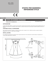
Montaggi consigliati
Recommended mountings
200 mm
3
Misure esterne
External measures
103 mm110 mm
340 mm
Staffe di fissaggio
Brackets
BB-L100
(100 x 75 mm)
BB-T100 (100 x 140 mm)
BB-T200 (200 x 140 mm)
BB-I100 (100 mm)
BB-I200 (200 mm)
1
2
2
9
8
6
5
4
3
1
10
12
11
1
2
1
2
7
10
11
13
13
ON ON
OFF OFF
ALARM CHECK CHECKRESPONSE
TIME ADJ
RECEIVER
TAMPER
2 NC NC 2 NC TS
ON ON
OFF OFF
A.Power
TRANSMITTER
TAMPER
NC 2 NC NC 2 NC
B.Power
1
3b-3
9
TAMPER
+ -
Terminale
Terminal
Trasmettitore
Transmitter
Uscita antisabotaggio
Tamper output
POWER
+ -
Ingresso alimentazione
Power supply input
ALARM OUT
Uscita d’allarme normalmente aperta
Normally open alarm output
Uscita d’allarme normalmente chiusa
Normally closed alarm output
Uscita d’allarme comunea
Common alarm output
Ricevitore
Receiver
COM
NC
NO
1. Remove the screw and detach the cover from the backplate.
2. Pull the wire through the wire entry.
3. Mount the detector.
4. Connect the wires to the terminals.
5. Adjust the beam alignment.
6. Replace the cover
Wall-mounting
3a-1. Break off the wall-mount knockouts.
3a-2. Use 15mm screws
Pole-mounting
3b-1. Break off the wire-entry knockout and pull the wires through.
3b-2. Break off the pole-mount knockouts.
3b-3. Using the brackets, mount the detector to the pole.

Qualora ostacoli (come alberi o panni appesi)
si frappongono tra trasmettitore e ricevitore.
In placements where obstacles (such as trees or even full
clothes-lines) are situated between the receiver and the transmitter.
Qualora la barriera sia piantata in maniera
non stabile.
In places where the installation base is
unstable.
Qualora la barriera sia esposta ai raggi diretti
del sole o ai fari delle automobili.
In places where sunlight or car headlights shine
directly onto the detector.
Qualora si dovessero usare più barriere, per coprire lunghe distanze,
è opportuno evitare l’interferenza tra i fasci di luce.
In case of using many groups of detectors when long distance protection
to avoid the mutual disturbance of light beams.
100
200
2.8
3.4
Distanza di copertura (m) Dispersione (m)
Protection distance (m) Dispersion (m)
BD-Q100
BD-Q200
Modello
Model
50 msec 306 msec 408 msec 700 msec80 msec
NO!
NO!
NOTE PER L’INSTALLAZIONE
DECLARATION OF CONFORMITY
DICHIARAZIONE DI CONFORMITÁ
via Fosso Antico, Centobuchi
63076 Monteprandone AP-Italy
tel +39 0735 705007
fax +39 0735 734912
www.inim.biz
DCMIINIEBDQ-R110-20110829
ISO 9001: 2008 REGISTERED COMPANY
The declaration of conformity to the Directive 2004/108/CE may be consulted
at www.inim.biz/dc.html
La dichiarazione di conformità alla Direttiva 2004/108/CE può essere
consultata sul sito: www.inim.biz/dc.html
• Seguire attentamente le istruzioni riportate in questa guida.
• Non toccare le superfici del sensore poiché tale operazione potrebbe causare
il malfunzionamento dei sensori stessi.
• Per la pulizia del sensore, togliere l’alimentazione e utilizzare un panno
morbido con un pò di alcool.
• Questo prodotto può ridurre la possibilità di intrusione, ma non garantisce
sicurezza assoluta. Concordare con l’installatore le necessarie precauzioni.
•
Dopo l’installazione e il settaggio di tutti i parametri, è opportuno testare il
corretto funzionamento della barriera.
WARNINGATTENZIONE
NO!
Ricevitore
Trasmettitore
NO!
Ricevitore
Trasmettitore
Ricevitore
Trasmettitori
Ricevitore
Receiver
Transmitter
Receiver
Transmitter
Receiver
Transmitters
Receiver
Distanza di copertura
Protection distance
Dispersione
Dispersion
Altezza di montaggio
Mounting height
(0.7 - 1 m)
ALLINEAMENTO
Un buon allineamento delle barriere è necessario ad ottimizzare la rivelazione dei sensori e
a prevenire falsi allarmi, specie in ambienti problematici.
Dopo il montaggio delle barriere, il loro allineamento si ottiene tramite la calibrazione della posizione delle lenti.
La calibrazione si effettua tramite la rotazione orizzontale o verticale dell’asse ottico rispetto la barriera:
questo può essere regolato all’interno di un angolo orizzontale di ±90° e verticale di ±10 °.
Il livello di allineamento è valutabile in due modi:
• I LED 1-10 si accendono a seconda dell’allineamento delle barriere;
più indicatori LED sono accesi, maggiore è l’allineamento tra sensori.
Un buon allineamento è caratterizzato dall’accensione almeno del settimo LED.
• Misura del voltaggio presso i connettori CHECK.
Inserire i puntali di un tester facendo attenzione alla polarità indicata e misurare il voltaggio.
Un buon allineamento genera un voltaggio di almeno 1,45V (il massimo misurabile è 1,85V).
CALIBRAZIONE DEL TEMPO DI RISPOSTA
Il tempo di risposta è l’intervallo di tempo al di sopra del quale se il ricevitore non riceve il segnale dal trasmettitore, la barriera va in allarme.
Questi è calibrabile tramite la vite all’interno del foro segnalato con “RESPONSE TIME ADJ”, permettendo una variazione da 50 a 700 msec.
If the receiver does not receive a signal from the transmitter within the set Response time, the detector will trigger an alarm.
The interval can be set by means of the screw inside the "RESPONSE TIME ADJ" entry and the values of the time are in a range from 50 to 700 msec.
Angolo verticale (20°)
Vertical direction (20°)
Angolo orizzontale (180°)
Horizontal direction (180°)
Obiettivo
Target
Mirino
Viewfinder
5678
1.15 1.30 1.45 1.60
Livello LED
Voltaggio misurato (V)
LED level
Measured voltage (V)
9 10
1.75 1.85
Trasmettitore
Ricevitore
Transmitter
Receiver
TROUBLESHOOTINGSOLUZIONE DEI PROBLEMI
Allineamento rapido
1.
Posizionare ad ON tutti gli interruttorie TS e 2 dei DIP switch,
sia nel trasmettitore che nel ricevitore.
2. Coprire temporaneamente le lenti del gruppo B
e regolare l’asse ottico del gruppo A finchè non si accende almeno il quinto
dei LED indicatori dell’allineamento, quindi rimuovere la copertura.
3. Ripetere la stessa procedura con la barriera inferiore (gruppo B).
4. Terminato l’allineamento, posizionare ad OFF gli interruttori TS.
Quick alignment
1.
Turn ON all the TS and 2 switches of the DIP switches,
both in the transmitter and in the receiver.
2. Cover the B group lens and adjust the optical axis of the A group
until the fifth of the level indicators LEDs is ON.
Once the beams are set, uncover the B group lens.
3. Repeat the same procedure for the lower beams (B group).
4. Once the alignment is set, turn OFF the TS switches.
Allineamento di precisione
1. Inserire
il mirino nell’apposito foro.
2. Spostare l’asse ottico della barriera finchè non si centra
il sensore opposto nell’obiettivo.
3. Posizionare ad ON l’interruttore TS e ad OFF gli interruttori 2
dei DIP switch, sia nel trasmettitore che nel ricevitore.
4. Posizionare ad ON gli interruttori 2 dei DIP switch delle
barriere superiori (gruppo A) e regolare l’asse ottico finchè non
si accende almeno il quinto dei LED indicatori dell’allineamento.
Terminata la regolazione, posizionare ad OFF gli interruttori 2.
5. Ripetere la stessa procedura con la barriera inferiore (gruppo B).
6. Terminato l’allineamento, posizionare ad OFF gli interruttori TS
e ad ON tutti gli interruttori 2.
Accurate alignment
1. Insert the viewfinder in its location
.
2. Adjust the optical axis until it is possible to see the opposite
detector in the center of the target.
3. Turn ON the TS switch and turn OFF the 2 switches
of the DIP switches, both in the transmitter and in the receiver.
4. Turn ON the 2 switches of the upper beams (A group) and
adjust the optical axis until the fifth of the level indicators LEDs is ON.
Once the beams are set, turn OFF the 2 switches.
5. Repeat the same procedure for the lower beams (B group).
6. Once the alignment is set, turn OFF the TS switches
and turn ON all the 2 switches.
INSTALLATION RECOMMENDATIONS
ALIGNMENT
Accurate beam-alignment optimizes the sensing capacity of the detector and thus improves security
and lowers the false-alarm rate, especially in difficult environments.
After mounting the devices, correct alignment is achieved through the lens positions.
It is attained by rotating the optical axis horizontally or vertically:
adjustments can be made within a ±90° horizontal angle and ±10° vertical angle.
The alignment level can be gauged in two ways:
• LEDs 1-10 light in accordance with the beam-alignment level;
the more LEDs that light, the better the beam alignment level.
A good level is indicated by the activation of 7 LEDs.
• Voltage measurement at CHECK connectors:
Insert the tester probes into the voltage-tester entries and measure the voltage.
A good level is indicated by a voltage of at least 1.45V (maximum measurable voltage is 1.85V).
RESPONSE TIME SETTING
The LEDs do not go ON Inadequate power supply. Check the power supply and wiring.
The alarm LED does not go ON
even when the beams are
violated.
1. The receiver is picking up beams from
other sources.
2. The three beams are not violated
simultaneously.
3. The response time is too short
1. Remove the reflecting object or
adjust the optical axis.
2. Increase the response time.
The alarm LED is always ON. 1. The optical axis is positioned incorrectly.
2. There are obstacles between the
transmitter and receiver.
3. The detector cover or lens is dirty.
1. Adjust the optical axis.
2. Remove the obstacle.
3. Clean the detector with a soft
lint-free cloth.
Intermittent alarm. 1. Improper wiring.
2. Inadequate power-supply.
3. Moving obstacles between the transmitter
and receiver.
4. Unstable mounting base.
5. The optical axis is not well positioned.
6. The response time is too short.
7. The lenses do not emit beams.
1. Check wiring.
2. Check the power supply.
3. Remove the obstacles.
4. Stabilize the base.
5. Adjust the optical axis.
6. Increase the response time.
7. Change the detector placements.
In the event of beam violation,
the alarm LED goes on but the
detector does not trigger an alarm.
1. There is a short circuit.
2. The terminal wiring has not been
completed correctly.
Check all wiring.
Trouble Possible cause Solution
I LED non si accendono. Non è fornita un’adeguata tensione Controllare l’alimentazione o i cavi.
Il LED di allarme non si accende,
nemmeno in caso di blocco
dei raggi.
1. I raggi al ricevitore provengono da altre
sorgenti.
2. Non tutti dei 3 raggi sono bloccati.
3. Il tempo di risposta è troppo corto.
1. Rimuovere l’oggetto esterno che
produce raggi o modificare l’asse
ottico.
2. Aumentare il tempo di risposta.
Il LED di allarme è sempre
acceso
1. L’asse ottico non è ben direzionato.
2. Ci sono impedimenti tra il trasmettitore e
il ricevitore.
3. Il coperchio del sensore o le lenti sono
sporche.
1. Regolare l’asse ottico.
2. Rimuovere gli impedimenti.
3. Pulire con un panno soffice.
Allarme intermittente. 1. Cablaggio non buono.
2. La tensione fornita non è sufficiente.
3. Impedimenti mobili tra trasmettitore e
ricevitore.
4. La base di montaggio non è stabile.
5. Asse ottico non ben regolato.
6. Tempo di risposta troppo breve.
7. Mancata emissione dei raggi.
1. Controllare il cablaggio.
2. Controllare l’alimentazione.
3. Rimuovere gli impedimenti.
4. Cambiare posizione ai sensori.
5. Stabilizzare la base.
6. Calibrare l’asse ottico.
7. Calibrare il tempo di risposta.
In caso di blocco dei raggi,
il LED d’allarme si accende, ma
il sensore non va in allarme.
1. C’è un corto circuito nei collegamenti.
2. I collegamenti ai terminali non sono fatti a
regola.
Controllare il cablaggio e i terminali
Problema Possibile causa Soluzione
• The device must be installed in accordance with the instructions herein.
• Do not touch the sensor surface as this may cause degradation of its performance.
• Ensure that the power supply is off before cleaning the detector with a soft lint-free cloth
dampened with a small amount of alcohol.
• This product reduces the risk of intrusions but cannot be considered a guarantee of
absolute security. Take all necessary precautions when protecting your premises.
• Once this product has been properly mounted and setup, carry out a walk test by
creating motion in the protected area.
-
 1
1
-
 2
2


in altre lingue
- English: INIM BD-Q200 User manual
Documenti correlati
Altri documenti
-
 Lince 1945-AN-6Z Istruzioni per l'uso
-
 Lince 1903-RICK-E200 Istruzioni per l'uso
-
 Politec Parvis Solar SMA Technical Manual
-
Menvier Security MBD100R Manuale utente
-
CARLO GAVAZZI SB4315915D25 Guida d'installazione
-
 Mighty Mule R4222 Istruzioni per l'uso
-
SICK MLG-2 ProNet Automation light grid Quickstart
-
 Elkron MWA60RT Guida d'installazione
-
ABB Orion1 Base Excerpts From The Instruction Manual
-


