Politec Parvis Solar SMA Technical Manual
- Tipo
- Technical Manual


POLITEC s.r.l. | Parvis Solar Sma – Ver. 1.1
2
INDEX
1
MAIN COMPONENTS
Pag. 3
2
ASSEMBLING THE CABLE PIT
Pag. 4
POSITIONING THE CABLE PIT
Pag. 6
3
INSTALLING THE BASE
Pag. 8
4
PHOTOVOLTAIC PANEL ORIENTATION
Pag. 9
5
INSTALLATION SAMPLES
Pag. 10
6
OPTICAL CONFIGURATION
Pag. 11
OPTICAL TRANSMITTER
Pag. 11
OPTICAL RECEIVER
Pag. 12
7
SANDOR WS TX BOARD
Pag. 13
8
SANDOR WS RX BOARD
Pag. 14
9
SETTING AND FUNCTION
Pag. 15
DIP SWITCH DESCRIPTION
Pag. 15
10
COLUMN ALIGNMENT
Pag. 17
11
CALIBRATION WITH SMA SYSTEM
Pag. 18
12
PARALLEL BEAMS CALIBRATION
Pag. 22
13
ALARM SENSITIVITY ADJUSTMENT
Pag. 23
14
CABLES
Pag. 24
15
TECHNICAL CHARACTERISTICS
Pag. 25
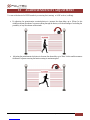
Installation recommendation
Verify that the beam tower is fully watertight once the cover and end caps have been correctly filled at the
end of the installation.
Use the cable glands supplied on the tower for all cabling must pass through the lower end cap using the
cable glands supplied. The missed used of proper accessories decrease the IP grade protection of the
tower.
Avoid any type of obstruction between the transmitter and receiver.
Avoid installing the receivers beams in a position where direct sunlight, at the same angle as the receivers
beams, can enter directly into optics especially at sunset and sunrise
Do not install multiple beams where the transmitter beam can interfere with other receiver beams. It is
always better place either transmitter or receivers back to back.

POLITEC s.r.l. | Parvis Solar Sma – Ver. 1.1
3
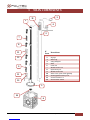
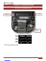
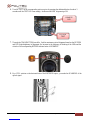
1 MAIN COMPONENTS
N°
Parte
Descrizione
1
Aluminum bar
2
IR pipe
3
Blind cap
4
Lamp Adapter
5
Base
6
Cable Pit
7
Mother board TX
8
Opitical RX/TX
9
Mother board RX
10
Base cover (with cable glands)
11
Rechargeable battery 3.6V
12
Power Board 3.6 V
13
Photovoltaic Panel
13
2
1
3
4
5
11
9
7
8
10
6
12
11
12


POLITEC s.r.l. | Parvis Solar Sma – Ver. 1.1
5
4. Insert and fix the screws in the other sides.
2.1 POSITIONING THE CABLE PIT
The placement of the cable pit for the columns PARVIS is made by concrete all around and not at the bottom,
keeping the top edge same level of ground
For columns PARVIS is possible to keep the top edge ten centimeters below the level of the ground so that it is
visible only the IR tube.
This type of placement is possible only when the cable pit is fixed directly into the ground and not in concrete
or pavement.

POLITEC s.r.l. | Parvis Solar Sma – Ver. 1.1
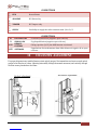
6
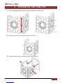
POSSIBLE CORRECTION OF THE INCORRECT
POSITIONING
Placement should be perpendicular to the ground. If the base is not in perfectly level, you can make small
adjustments through the regulation of the inserts in the cablepit.
Loosening the insert on the side to correct inclination you get the increase to the correct position
Wrong positioning.
Example of
setting.
Correct positioning by
adjusting inserts.

POLITEC s.r.l. | Parvis Solar Sma – Ver. 1.1
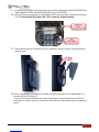
7
3 INSTALLING THE BASE
Ensure that all the cabling to and from the Parvis beam passes through the supplied cable glands that should be
fitted to the base of the tower. Use the central cable gland for the pre-wired light cabling.
The base cover fitted with the cable glands
Once the cabling is completed the base cover has to be fixed to the base.

POLITEC s.r.l. | Parvis Solar Sma – Ver. 1.1
8
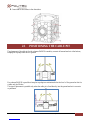
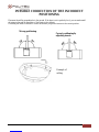
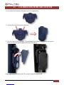
4 PHOTOVOLTAIC PANEL ORIENTATION
Using screws of the cap you can rotate the plastic profile of 120 ° at a time to expose the solar panel as much as
possible in the midday sun.
You can make other minor corrections using the slots
FIXING SCREW
CAP
FIXING SCREW
BASE


POLITEC s.r.l. | Parvis Solar Sma – Ver. 1.1
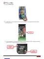
13
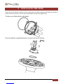
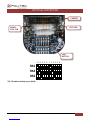
8 SANDOR WS MOTHER BOARD RX
N.B.: When the motherboard is supplied the LED ON will flash.
LED TEST
BATTERY
CONNECTION
3,6 V – 19 Ah
3,6 V
3,0 V
TAMPER
ALARM
TAMPER
SUPPLY
INTERVENTION
DELAY
ADJUSTING
BATTERY LOW (BL)
SIGNAL LOW (SL)
AND FOR REMOTE
(AND)
DIP SWITCH
ANTIMASK P OUTPUT
(AMK)

POLITEC s.r.l. | Parvis Solar Sma – Ver. 1.1
14
9 SETTING AND FUNCTION
DIP SWITCH
The board has Dip Switches to set different functions:
BANCO A 4 DIP SWITCH SCHEDA TX
1
TEST
In ON position goes in test. The TEST LED start blinking.
2
/
Not utilized
3
BEAM ON
It puts in test all TX during alignment (DIP 1 ON). Test LED fixed ON.
4
BEAM OFF
It puts OFF all TX during alignment (DIP 1 ON). Test LED fixed ON.
ON
1
2
3
4
5
6
7
8
9
10
i.e.: Function AND 1-2 with 3 beams
8 DIP SWITCHES
1
AND
At least 2 optical must be interrupted to give alarm
2
AND 1-2
AND function only for 1st and 2nd beam, usefull in case of growing grass
3
BEAM 3
First 3 RX are active
4
BEAM 4
/
5
BEAM 5
/
6
BEAM 6
/
7
S. LOW
FOG disqualification active
8
A. CRAWL
ON - Anti crawling active. In this condition if the first beam (lower) is interrupted for
more than 2 seconds, it will generate an alarm, independently of its configuration
(i.e. AND)
9
AMK
/
10
TEST
Active or disable the TEST

POLITEC s.r.l. | Parvis Solar Sma – Ver. 1.1
15
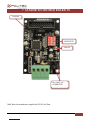
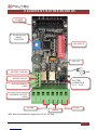
CONNECTOR 8
1
HTR
Non utilizzato
2
3
ALLARME
NC Alarm relay
4
5
TAMPER
NC Tamper relay
6
7
SUPPLY
Possibility to supply the radio trasmitter with 3,0 or 3,6 V
8
CONNECTOR 4
BL
BATTERY LOW
Low battery indication (negative open collector)
SL
SIGNAL LOW
Fog disqualification (negative open collector)
AND
REMOTE
CONTROL
Giving a positive (3,6 V) the AND function is activated
AMK
ANTIMASK
Segnalazione di mascheramento data dalla chiusura al negativo di un open
collector.
10 COLOUMN ALIGNMENT
For proper alignment once installed barriers orient optical groups of the transmitters and receivers each optical
groups in the direction of others. Adjusting horizontally through the manual movement, and vertically through
the front screws placed above the lenses.
Vertical adjustment
Horizontal adjustment

POLITEC s.r.l. | Parvis Solar Sma – Ver. 1.1
16
11 CALIBRATION WITH SMA SYSTEM
You can improve the calibration through the use of the supplied filter
1. Fold the device by following the folds preset
2. Place the filter in front of the optics TX positioning the two hooks on the pins of the fork optics to
effectively search the signal alignment with critical conditions.
Simply applying the filter only on the TX, no need to repeat the operation RX.

POLITEC s.r.l. | Parvis Solar Sma – Ver. 1.1
17
3. Connect the battery cable.
4. Put in ON DIP 10 on the motherboard receiver until the entrance to the programming mode indicated by
the flashing LED test.
5. Start the alignment of the barrier is on activating the transmitter optics TX TEST, pressing the dedicated
button for about 3 seconds until the TEST LED turns orange.
DIP 10
ORANGE
LED
TEST
BUTTON

POLITEC s.r.l. | Parvis Solar Sma – Ver. 1.1
18
6. Turn the TEST on the corresponding optics receiver by pressing the dedicated button for about 3
seconds until the TEST LED turns orange , the Buzzer and LED alignment go ON.
7. Through the TRANSMITTER lens shifts , find the maximum optical alignment based on the BUZZER
and LED (high-brightness) of alignment, the 'increase in the frequency of blinking of the LEDs and the
whistle of the corresponding BUZZER indicate better ALIGNMENT.
8. By a FULL rotation on the horizontal axis of the RECEIVER optics , you make the SCANNING of the
optical signal.
BUTTON
TEST
ORANGE
LED

POLITEC s.r.l. | Parvis Solar Sma – Ver. 1.1
19
9. Rotating the optical RX find the maximum value of which corresponds to the ALIGNMENT LED
(high-brightness) FIXED and whistle CONTINUOUS of the BUZZER.
10. Exit the function by repressing the ALIGNMENT TEST button for about 3 seconds on both optics
(TX-RX) ensuring that the orange LED TEST is shown in original condition.
11. When finished, remove the shade that acts as a attenuator, with the certainty of having found the
optimum value.
12. Once the alignment of all the beams is finished, re-press the test button on the motherboard for 5
seconds until the LED turns off.
For the next 30 seconds the barrier will sound continuously in case of alignment not effective or
interruption of a beam; correct the orientation of the columns so that the buzzer emits no longer any
sound.
.
TEST
BUTTON
ORANGE
LED

POLITEC s.r.l. | Parvis Solar Sma – Ver. 1.1
20
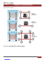
12 PARALLEL BEAMS CALIBRATION
Put TEST optics TX1 and RX1 and proceed with the calibration as previously explained.
Put TEST optics TX2 and RX2 and proceed with the calibration as previously explained.
N.B.: During the alignment phase of a transmitter the other TX are switched off automatically.
RX2
TX2
RX1
TX1
RX2
TX2
RX1
TX1
RX2
TX2
RX1
TX1
RX2
TX2
RX1
TX1
La pagina si sta caricando...
La pagina si sta caricando...
La pagina si sta caricando...
La pagina si sta caricando...
-
 1
1
-
 2
2
-
 3
3
-
 4
4
-
 5
5
-
 6
6
-
 7
7
-
 8
8
-
 9
9
-
 10
10
-
 11
11
-
 12
12
-
 13
13
-
 14
14
-
 15
15
-
 16
16
-
 17
17
-
 18
18
-
 19
19
-
 20
20
-
 21
21
-
 22
22
-
 23
23
-
 24
24


Politec Parvis Solar SMA Technical Manual
- Tipo
- Technical Manual
in altre lingue
- English: Politec Parvis Solar SMA
Altri documenti
-
 INIM BD-Q200 Manuale utente
-
INIM TRIPLICATE PHOTOELECTRIC BEAM Guida d'installazione
-
CAME BQ810AS-BQ815AS-BE820AS-BE825AS Guida d'installazione
-
PRASTEL FOTO9S2A Manuale del proprietario
-
WisyCom MCR41S-42S Manuale utente
-
SEA USER 1 Manuale del proprietario
-
BFT Ares Manuale del proprietario
-
-
-
