Indesit K6G11S(W)/I Guida utente
- Categoria
- Piani cottura
- Tipo
- Guida utente

Cucina
Installazione e uso
Cooker
Installation and use
K6G11S/I

Cucina con forno elettrico
Istruzioni per l'installazione e l'uso 3
Cooker with electric oven
Instructions for installation and use 12

3
Avvertenze
1 Questo apparecchio è stato concepito per un uso di tipo non professionale
all’interno di abitazione.
2 Queste istruzioni sono valide solo per i paesi di destinazione i cui simboli
figurano sul libretto e sulla targa matricola dell’apparecchio.
3 Questo apparecchio riguarda un apparecchio di classe 1
(isolato) o classe 2 - sottoclasse 1 (incassato tra 2 mobili).
4 Prima di utilizzare l’apparecchio leggere attentamente le avvertenze conte-
nute nel presente libretto in quanto forniscono importanti indicazioni riguar-
danti la sicurezza di installazione, d’uso e di manutenzione. Conservare con
cura questo libretto per ogni ulteriore consultazione.
5 Dopo aver tolto l’imballaggio assicurarsi dell’integrità dell’apparecchio. In
caso di dubbio non utilizzare l’apparecchio e rivolgersi a personale profes-
sionalmente qualificato. Gli elementi dell’imballaggio (sacchetti in plastica,
polistirolo espanso, chiodi, ecc.) non devono essere lasciati alla portata dei
bambini in quanto potenziali fonti di pericolo.
6 L’installazione deve essere effettuata secondo le istruzioni del costruttore
da personale professionalmente qualificato. Una errata installazione può
causare danni a persone, animali o cose, nei confronti dei quali il costruttore
non può essere considerato responsabile.
7 La sicurezza elettrica di questo apparecchio è assicurata soltanto quando
lo stesso è correttamente collegato ad un efficiente impianto di messa a
terra come previsto dalle vigenti norme di sicurezza elettrica. E’ necessario
verificare questo fondamentale requisito di sicurezza e, in caso di dubbio,
richiedere un controllo accurato dell’impianto da parte di personale profes-
sionalmente qualificato. Il costruttore non può essere considerato respon-
sabile per eventuali danni causati dalla mancanza di messa a terra dell’im-
pianto.
8 Prima di collegare l’apparecchio accertarsi che i dati di targa (posti sull’ap-
parecchio e/o sull’imballo) siano rispondenti a quelli della rete di distribuzio-
ne elettrica e gas.
9 Verificare che la portata elettrica dell’impianto e delle prese di corrente siano
adeguate alla potenza massima dell’apparecchio indicata in targa. In caso
di dubbio rivolgersi ad una persona professionalmente qualificata.
10 All’installazione occorre prevedere un interruttore omnipolare con distanza
di apertura dei contatti uguale o superiore a 3 mm.
11 In caso di incompatibilità tra la presa e la spina dell’apparecchio fare sosti-
tuire la presa con altra di tipo adatto da personale professionalmente qua-
lificato. Quest’ultimo, in particolare, dovrà anche accertare che la sezione
dei cavi della presa sia idonea alla potenza assorbita dall’apparecchio. In
generale è sconsigliabile l’uso di adattatori, prese multiple e/o prolunghe.
Qualora il loro uso si rendesse indispensabile è necessario utilizzare sola-
mente adattatori semplici o multipli e prolunghe conformi alle vigenti norme
di sicurezza, facendo però attenzione a non superare il limite di portata in
valore di corrente, marcato sull’adattatore semplice e sulle prolunghe, e
quello di massima potenza marcato sull’adattatore multiplo.
12 Non lasciare l’apparecchio inutilmente inserito. Spegnere l’interruttore gene-
rale dell’apparecchio quando lo stesso non è utilizzato, e chiudere il rubinet-
to del gas.
13 Non ostruire le aperture o fessure di ventilazione o di smaltimento calore.
14 Il cavo di alimentazione di questo apparecchio non deve essere sostituito
dall’utente. In caso di danneggiamento del cavo, o per la sua sostituzione,
rivolgersi esclusivamente ad un centro di assistenza tecnica autorizzato
dal costruttore.
15 Questo apparecchio dovrà essere destinato solo all’uso per il quale è stato
espressamente concepito. Ogni altro uso (ad esempio: riscaldamento di
ambienti) è da considerarsi improprio e quindi pericoloso. Il costruttore non
può essere considerato responsabile per eventuali danni derivanti da usi
impropri, erronei ed irragionevoli.
16 L’uso di un qualsiasi apparecchio elettrico comporta l’osservanza di alcune
regole fondamentali. In particolare:
• non toccare l’apparecchio con mani o piedi bagnati o umidi
• non usare l’apparecchio a piedi nudi
• non usare, se non con particolare cautela, prolunghe
• non tirare il cavo di alimentazione, o l’apparecchio stesso, per staccare
la spina dalla presa di corrente.
• non lasciare esposto l’apparecchio ad agenti atmosferici (pioggia, sole,
ecc.)
• non permettere che l’apparecchio sia usato dai bambini o da incapaci,
senza sorveglianza
17 Prima di effettuare qualsiasi operazione di pulizia o di manutenzione,
disinserire l’apparecchio dalla rete di alimentazione elettrica, o staccando la
spina, o spegnendo l’interruttore dell’impianto.
18 In caso di guasto e/o di cattivo funzionamento dell’apparecchio, spegnerlo,
chiudere il rubinetto del gas e non manometterlo. Per l’eventuale riparazione
rivolgersi solamente ad un centro di assistenza tecnica autorizzato e richie-
dere l’utilizzo di ricambi originali. Il mancato rispetto di quanto sopra può
compromettere la sicurezza dell’apparecchio.
19 Allorché si decida di non utilizzare più l’apparecchio, si raccomanda di
renderlo inoperante tagliandone il cavo di alimentazione, dopo aver stacca-
to la spina dalla presa di corrente. Si raccomanda inoltre di rendere innocue
quelle parti dell’apparecchio suscettibili di costituire un pericolo, special-
mente per i bambini che potrebbero servirsi dell’apparecchio fuori uso per i
propri giochi.
20 Sui bruciatori non debbono essere poste pentole instabili o deformate onde
evitare incidenti per rovesciamento. Posizionatele sul piano di cottura in
modo che i manici siano rivolti verso l’interno, per evitare urti accidentali.
21 Alcune parti dell’apparecchio rimangono calde per lungo tempo dopo l’uso.
Fate attenzione a non toccarle.
22 Non utilizzate liquidi infiammabili (alcool, benzina...) in vicinanza all’appa-
recchio mentre questo è in uso.
23 Usando piccoli elettrodomestici nelle vicinanze del piano fate attenzione
che il cavo di alimentazione non finisca su parti calde.
24 Controllare sempre che le manopole siano nella posizione “•”/”¡” quando
l’apparecchio non è utilizzato.
25 Durante l'uso dell'apparecchio gli elementi riscaldanti e al-
cune parti della porta forno diventano molto calde. Fare
attenzione a non toccarle e tenere i bambimi a distanza.
26 Gli apparecchi gas necessitano, per un corretto funziona-
mento, di un regolare ricambio d’aria. Accertarsi che nella
loro installazione siano rispettati i requisiti richiesti nel pa-
ragrafo relativo al “Posizionamento”.
27 Il coperchio vetro (presente solo su alcuni modelli) può frantumarsi nel caso
si surriscaldi, quindi è necessario che tutti i bruciatori o le eventuali piastre
elettriche risultino spente prima di chiudere il coperchio.
28 Se la cucina viene posta su di un piedistallo, prendere adeguati accorgimen-
ti affinchè l'apparecchio non scivoli dal piedistallo stesso.
29 Le superfici interne del cassetto (se presente) possono diventare calde.
Per garantire l’efficienza e la sicurezza di questo elettrodomestico:
• rivolgetevi esclusivamente a centri di assistenza tecnica autorizzati
• richiedete sempre l’utilizzo di parti di ricambio originali

4
Istruzioni per l’installazione
Le istruzioni che seguono sono rivolte all’installatore qua-
lificato affinchè compia le operazioni di installazione
regolazione e manutenzione tecnica nel modo più corret-
to e secondo le norme in vigore.
Importante: qualsiasi intervento di regolazione, ma-
nutenzione etc. deve essere eseguito con la cucina
elettricamente disinserita.
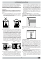
Posizionamento
Importante: questo apparecchio può essere installato e
funzionare solo in locali permanentemente ventilati se-
condo le prescrizioni delle Norme UNI-CIG 7129 e 7131 e
successivi aggiornamenti in vigore. Debbono essere os-
servati i seguenti requisiti:
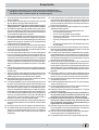
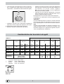
a) Il locale deve prevedere un sistema di scarico all’ester-
no dei fumi della combustione, realizzato tramite una
cappa o tramite un elettroventilatore che entri auto-
maticamente in funzione ogni volta che si accende l’ap-
parecchio.
In camino o in canna fumaria ramificata Direttamente all’esterno
(riservata agli apparecchi di cottura)
b)
Il locale deve prevedere un sistema che consenta l’af-
flusso dell’aria necessaria alla regolare combustione. La
portata di aria necessaria alla combustione non deve
essere inferiore a 2 m
3
/h per kW di potenza installata. Il
sistema può essere realizzato prelevando direttamente
l’aria dall’esterno dell’edificio tramite un condotto di al-
meno 100 cm
2
di sezione utile e tale che non possa es-
sere accidentalmente ostruito. Per gli apparecchi privi sul
piano di lavoro, del dispositivo di sicurezza per assenza
di fiamma, le aperture di ventilazione debbono essere
maggiorate nella misura del 100%, con un minimo di
200cm
2
(Fig. A). Ovvero, in maniera indiretta da locali
adiacenti, dotati di un condotto di ventilazione con l’ester-
no come sopra descritto, e che non siano parti comuni
dell’immobile, o ambienti con pericolo di incendio, o ca-
mere da letto (Fig. B).
Particolare A Locale Locale da
adiacente ventilare
A
Esempi di aperture di ventilazione Maggiorazione della fessura fra
per l’aria comburente porta e pavimento
Fig. A Fig. B
c) Un utilizzo intensivo e prolungato dell’apparecchio può
necessitare di una aerazione supplementare per esem-
pio l’apertura di una finestra o una aerazione più effi-
cace aumentando la potenza di spirazione meccanica
se essa esiste.
d) I gas di petrolio liquefatti, più pesanti dell’aria, rista-
gnano verso il basso. Quindi i locali contenenti bidoni
di GPL debbono prevedere delle aperture verso l’ester-
no così da permettere l’evacuazione dal basso delle
eventuali fughe di gas. Pertanto i bidoni di GPL, siano
essi vuoti o parzialmente pieni, non debbono essere
installati o depositati in locali o vani a livello più basso
del suolo (cantinati, ecc.). É opportuno tenere nel lo-
cale solo il bidone in utilizzo, collocato in modo da non
essere soggetto all’azione diretta di sorgenti di calore
(forni, camini, stufe, ecc.) capaci di portarlo a tempe-
rature superiori ai 50°C.
Livellamento (presente solo su alcuni modelli)
Nella parte inferiore dell’apparecchio si trovano 4 piedini
di sostegno regolabili con viti che permettono di migliora-
re il livellamento dell’apparecchio, se necessario. E’ indi-
spensabile che l’apparecchio sia posizionato in modo
uniforme.
Montaggio gambe (presente solo su alcuni modelli)
Vengono fornite delle gambe da montare ad incastro sot-
to la base della cucina.
Installazione della cucina
E’ possibile l’installazione a fianco di mobili la cui altezza
non superi quella del piano di lavoro. La parete a contatto
con la parete posteriore della cucina deve essere in ma-
teriale ininfiammabile. Durante il funzionamento la pare-
te posteriore della cucina può raggiungere una tempera-
tura di 50°C superiore a quella ambiente. Per una corretta
installazione della cucina vanno osservate le seguenti
precauzioni:
a) I mobili situati a fianco, la cui altezza superi quella del
piano di lavoro, debbono essere situati ad almeno 200
mm. dal bordo del piano stesso.

5
b) Le cappe debbono essere installate secondo i requisiti
richiesti nei libretti istruzioni delle cappe stesse e co-
munque ad una distanza minima di 650 mm.
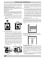
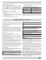
c) Allorchè la cucina venga installata sotto un pensile,
quest’ultimo dovrà mantenere una distanza minima dal
piano di 700 mm (millimetri). I mobili adiacenti alla cap-
pa dovranno mantenere una distanza minima dal pia-
no di 420 mm. come da Fig. C e D.
HOOD
420
Min.
min. 650 mm. with hood
min.
700 mm. without hood
mm.
600
Min. mm.
420
Min. mm.
HOOD
900
Min. mm.
420
Min.
min.
650
mm. with hood
min.
700
mm. without hood
mm.
420
Min. mm.
Fig. C Fig. D
Collegamento gas
Il collegamento dell’apparecchio alla tubazione o alla bombola
del gas dovrà essere effettuato come prescritto dalle Norme
UNI-CIG 7129 e 7131 e successivi aggiornamenti, solo dopo essersi accertati
che esso è regolato per il tipo di gas con cui sarà alimentato. In caso contrario
eseguire le operazioni indicate al paragrafo “Adattamento ai diversi tipi di gas”.
Su alcuni modelli l’alimentazione del gas può avvenire indifferentemente da
destra o da sinistra a seconda dei casi; per cambiare il collegamento è neces-
sario invertire il portagomma con il tappo di chiusura e sostituire la guarnizione
di tenuta (in dotazione con l’apparecchio). Nel caso di alimentazione con gas
liquido, da bombola, utilizzare regolatori di pressione conformi alle Norme UNI
EN 12864 e successivi aggiornamenti.
Importante: per un sicuro funzionamento, per un adeguato uso dell’energia e
maggiore durata dell’apparecchiatura, assicurarsi che la pressione di alimenta-
zione rispetti i valori indicati nella tabella 1 “Caratteristiche dei bruciatori ed
ugelli”.
Allaccio con tubo flessibile
Eseguire il collegamento per mezzo di un tubo flessibile
per gas rispondente alle caratteristiche indicate nelle nor-
me UNI-CIG 7140. Il diametro interno del tubo da utilizza-
re deve essere:
- 8mm per alimentazione con gas liquido;
- 13mm per alimentazione con gas metano.
In particolare, per la messa in opera di tali tubi flessibili,
debbono essere rispettate le seguenti prescrizioni:
• Non deve essere in nessun punto del suo percorso a
contatto con parti che siano a temperature maggiori di
50°C;
• Abbia una lunghezza inferiore a 1500 mm;
• Non sia soggetto ad alcun sforzo di trazione e di tor-
sione, inoltre non deve presentare curve eccessiva-
mente strette o strozzature;
• Non venga a contatto con corpi taglienti, spigoli vivi e
con parti mobili o schiacciato;
• Deve essere facilmente ispezionabile lungo tutto il per-
corso allo scopo di poter controllare il suo stato di con-
servazione;
Assicurarsi che il tubo sia ben calzato alle sue due estre-
mità e fissarlo per mezzo di fascette di serraggio confor-
mi alla UNI-CIG 7141. Qualora una o più di queste condi-
zioni non possa essere rispettata, bisognerà ricorrere ai
tubi metallici flessibili, conformi alla norma UNI-CIG 9891.
Allorchè la cucina venga installata secondo le condizioni
della classe 2 sottoclasse 1 è opportuno collegarsi alla
rete gas solamente tramite tubo metallico flessibile con-
forme alla UNI-CIG 9891.
Allaccio con tubo flessibile in acciaio inossidabile a
parete continua con attacchi filettati
Eliminare il portagomma già presente sull’apparecchio. Il
raccordo di entrata del gas all’apparecchio è filettato 1/2
gas maschio cilindrico. Utilizzare esclusivamente tubi con-
formi alla Norma UNI-CIG 9891 e guarnizioni di tenuta
metalliche in alluminio conformi alla UNI 9001-2 o guarni-
zioni in gomma conformi alla UNI EN 549. La messa in
opera di tali tubi deve essere effettuata in modo che la
loro lunghezza, in condizioni di massima estensione, non
sia maggiore di 2000 mm.
Controllo tenuta
Importante: ad installazione ultimata controllare la perfetta te-
nuta di tutti i raccordi utilizzando una soluzione saponosa e mai
una fiamma.
Ad allacciamento avvenuto assicurarsi che il tubo metallico fles-
sibile non venga a contatto con parti mobili o schiacciato.
Allacciamento del cavo di alimentazione alla rete
Montare sul cavo una spina normalizzata per il carico in-
dicato sulla targhetta caratteristiche, nel caso di collega-
mento diretto alla rete è necessario interporre tra l’appa-
recchio e la rete un interruttore omnipolare con apertura
minima fra i contatti di 3 mm. dimensionato al carico e
rispondente alle norme in vigore (il filo di terra non deve
essere interrotto dall’interruttore). Il cavo di alimentazio-
ne deve essere posizionato in modo che non raggiunga
in nessun punto una temperatura superiore di 50°C a
quella ambiente. Prima di effettuare l’allacciamento ac-
certarsi che:
• la valvola limitatrice e l’impianto domestico possano
sopportare il carico dell’apparecchiatura (vedi targhetta
caratteristiche);
• l’impianto di alimentazone sia munito di efficace colle-
gamento a terra secondo le norme e le disposizioni di
legge;
• la presa o l’interruttore omnipolare siano facilmente
raggiungibili con il piano installato.
N.B: non utilizzare riduzioni, adattatori o derivatori in quan-
to essi potrebbero provocare riscaldamenti o bruciature.
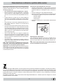
Adattamento del piano ai diversi tipi di gas
Per adattare la cucina ad un tipo di gas diverso da quello
per il quale essa è predisposta (indicato sulla etichetta
fissata al coperchio), occorre effettuare le seguenti ope-
razioni:
a) Sostituire il portagomma già montato con quello con-
tenuto nella confezione “accessori della cucina”.
Attenzione: il portagomma per gas metano e per gas cit-
tà è lo stesso. (Il portagomma per gas liquido porta
stampigliato il numero 8, quello per gas metano il numero
13). Avvalersi comunque di una guarnizione di tenuta nuo-
va.
b) Sostituzione degli ugelli dei bruciatori del piano:
• togliere le griglie e sfilare i bruciatori dalle loro sedi;

6
• svitare gli ugelli, servendosi di una chiave a tubo da 7
mm, e sostituirli con quelli adatti al nuovo tipo di gas
(vedi tabella 1 “Caratteristiche dei bruciatori ed ugelli”).
• rimettere in posizione tutti i componenti seguendo le
operazioni inverse rispetto alla sequenza di cui sopra.
c) Regolazione minimi dei bruciatori del piano:
•
portare il rubinetto sulla posizione di minimo;
• togliere la manopola ed agire sulla vite di regolazione
posta all’interno o di fianco all’astina del rubinetto fino
ad ottenere una piccola fiamma regolare.
N.B.: nel caso dei gas liquidi, la vite di regolazione
dovrà essere avvitata a fondo.
• verificare poi che ruotando rapidamente il rubinetto
dalla posizione di massimo a quella di minimo, non si
abbiano spegnimenti del bruciatore.
d) Regolazione aria primaria dei bruciatori del piano:
I bruciatori non necessitano di alcuna regolazione del-
l’aria primaria.
Attenzione
Al termine dell’operazione sostituire la vecchia etichetta
di taratura con quella corrispondente al nuovo gas di uti-
lizzo, reperibile presso i nostri Centri Assistenza Tecnica.
Nota
Qualora la pressione del gas utilizzato sia diversa (o va-
riabile) da quella prevista, è necessario installare, sulla
tubazione d’ingresso un appropriato regolatore di pres-
sione (secondo EN 88-1 e EN 88-2).
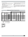
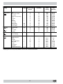
Caratteristiche dei bruciatori ed ugelli
Tabella 1 Gas liquido Gas naturale
Bruciatore Diametro
(mm)
Potenza termica
kW (p.c.s.*)
By-pass
1/100
Ugello
1/100
Portata *
g/h
Ugello
1/100
Portata *
l/h
Nomin. Ridot. (mm) (mm) *** ** (mm)
Rapido
(Grande) (R)
100 3,00 0,7 41 86 218 214 116 286
Semi Rapido
(Medio) (S)
75 1,90 0,4 30 70 138 136 106 181
Ausiliario
(Piccolo) (A)
55 1,00 0,4 30 50 73 71 79 95
Pressioni di
alimentazione
Nominale (mbar)
Minima (mbar)
Massima (mbar)
28-30
20
35
37
25
45
20
17
25
* A 15°C e 1013 mbar-gas secco
** Propano P.C.S. = 50,37 MJ/Kg
*** Butano P.C.S. = 49,47 MJ/Kg
Naturale P.C.S. = 37,78 MJ/m
3
S
S
R
A
K6G11S/I

7
Caratteristiche tecniche
Dimensioni utili del forno:
larghezza cm. 43,5
profondità cm. 43
altezza cm. 32
Volume utile del forno:
litri 60
Dimensioni utili del cassetto scaldavivande:
larghezza cm. 46
profondità cm. 42
altezza cm. 8,5
ENERGY LABEL
Direttiva 2002/40/CE sull'etichetta dei forni elettrici
Norma EN 50304
Consumo energia dichiarazione Classe convezione Naturale
funzione di riscaldamento: Statico
Tensioni e frequenza di alimentazione:
vedi targhetta caratteristiche
Bruciatori:
adattabili a tutti i tipi di gas indicati nella terghetta
caratteristiche
Questa apparecchiatura è conforme alle seguenti
Direttive Comunitarie:
- 73/23/CEE del 19/02/73 (Bassa Tensione) e successi-
ve modificazioni;
- 89/336/CEE del 03/05/89 (Compatibilità Elettromagne-
tica) e successive modificazioni;
- 90/396/CEE del 29/06/90 (Gas) e successive
modificazioni;
- 93/68/CEE del 22/07/93 e successive modificazioni.
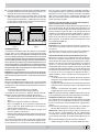
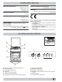
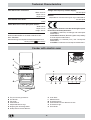
La cucina con forno elettrico
H
A Piano di contenimento eventuali trabocchi
B Bruciatore a gas
D Griglia del piano di lavoro
E Cruscotto
F Piedini o gambe regolabili
G Leccarda o piatto di cottura
H Dispositivo di sicurezza dei bruciatori del piano
K Griglia ripiano del forno
L Manopola di selezione
M Manopola del termostato
N Manopole di comando dei bruciatori a gas del piano
di cottura
O Spia termostato
S La manopola del contaminuti
F
A
E
K
G
D
B
O
LMS N

8
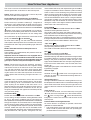
Istruzioni per l’uso
La selezione delle varie funzioni presenti nella cucina av-
viene agendo sui dispositivi ed organi di comando posti
sul cruscotto dello stesso.
Attenzione: Prima dell'uso, togliere tassativamente le pel-
licole in plastica poste ai lati dell'apparecchio
Le manopole di comando dei bruciatori a gas del
piano di cottura (N)
In corrispondenza di ciascuna delle manopole è indicata,
con un cerchietto pieno
•, la posizione del bruciatore a
gas da essa comandato. Per accendere uno dei bruciato-
ri, avvicinare allo stesso una fiamma o un accenditore,
premere a fondo e ruotare la manopola corrispondente in
senso antiorario fino alla posizione di massimo
. Cia-
scun bruciatore può funzionare al massimo della sua po-
tenza, al minimo, o con potenze intermedie. In relazione a
queste diverse prestazioni, sulla manopola, oltre alla po-
sizione di spento, individuata dal simbolo
• quando que-
sto è posto in corrispondenza della tacca di riferimento,
sono indicate le posizioni di massimo
e di minimo .
Esse si ottengono facendo ruotare la manopola im senso
antiorario dalla posizione di spento. Per spegnere il bru-
ciatore occorre invece ruotare la manopola in senso ora-
rio fino all’arresto (corrispondente di nuovo al simbolo
•).
Modelli con dispositivo di sicurezza contro fughe di
gas per i bruciatori del piano
Potete identificare questi modelli per la presenza del di-
spositivo (Vedi dettaglio H).
Importante: dato che i bruciatori del piano sono dotati di
dispositivo di sicurezza, dopo l’accensione del bruciatore,è
necessario mantenere premuta la manopola per cir-
ca 3 secondi in modo da consentire il passaggio del gas
finchè non si scalda la termocoppia di sicurezza.
Attenzione: Alla prima accensione consigliamo di far fun-
zionare il forno a vuoto per circa mezz'ora con il termo-
stato al massimo e a porta chiusa. Quindi trascorso tale
tempo spegnerlo, aprite la porta ed areare il locale. L'odore
che talvolta si avverte durante questa operazione è dovu-
to all'evaporazione delle sostanze usate per proteggere il
forno durante l'intervallo di tempo che intercorre tra la pro-
duzione e l'installazione del prodotto.
Attenzione: Utilizzare il primo ripiano dal basso solamente
nel caso di cotture con girarrosto (ove presente). Per le
altre cotture non utilizzate mai il primo ripiano dal basso e
non appoggiate mai oggetti sul fondo del forno mentre
state cuocendo perchè potreste causare danni allo smal-
to. Ponete sempre i Vostri recipienti di cottura (pirofile,
pellicole di alluminio, ecc. ecc.) sulla griglia in dotazione
con l’apparecchio appositamente inserita nelle guide del
forno.
Forno Statico
Posizione manopola termostato “M”: Tra 60°C e Max.
In questa posizione si accendono i due elementi riscaldanti
inferiore e superiore. E’ il classico forno della nonna che è
stato però portato ad un eccezionale livello di distribuzione
della temperatura e di contenimento dei consumi. Il forno
statico resta insuperato nei casi in cui si debbano cucinare
piatti i cui ingredienti risultano composti da due o più
elementi che concorrono a formare un piatto unico come
ad esempio: cavoli con costine di maiale, baccalà alla
spagnola, stoccafisso all’anconetana, teneroni di vitello
con riso etc... Ottimi risultati si ottengono nella
preparazione di piatti a base di carni di manzo o vitello
quali: brasati, spezzatini, gulasch, carni di selvaggina,
cosciotto e lombo di maiale etc... che necessitano di
cottura lenta con costante aggiunta di liquidi. Resta
comunque il miglior sistema di cottura per i dolci, per la
frutta e per le cotture con recipienti coperti specifici per le
cotture al forno. Nella cottura al forno statico utilizzate un
solo ripiano, in quanto su più ripiani si avrebbe una cattiva
distribuzione della temperatura. Usando i diversi ripiani a
disposizione potrete bilanciare la quantità di calore tra la
parte superiore ed inferiore. Se la cottura necessita di
maggior calore dal basso o dall’alto, utilizzate
rispettivamente i ripiani inferiori o superiori.
Forno Dolce
Posizione manopola termostato “M”: Tra 60°C e Max.
Si accende l’elemento riscaldante inferiore.
Questa funzione è indicata per la cottura di cibi delicati, in
particolare i dolci che necessitano di lievitazione, in quanto
viene facilitata dal calore proveniente dal basso.
Viene fatto notare che le temperature più elevate vengo-
no raggiunte in tempi piuttosto lunghi, pertanto in questi
casi è consigliabile utilizzare la funzione “Forno Statico”.
Forno “sopra”
Posizione manopola termostato “M”: Tra 60°C e Max.
Si accende l’elemento riscaldante superiore.
Questa funzione può essere utilizzata per ritocchi di cot-
tura.
Grill
Posizione manopola termostato “M”: Max.
Si accende l’elemento riscaldante superiore centrale.
La temperatura assai elevata e diretta del grill consente
la immediata rosolatura superficiale dei cibi che,
ostacolando la fuoriuscita dei liquidi, li mantiene più teneri
internamente. La cottura al grill è particolarmente
consigliata per quei piatti che necessitano di elevata
temperatura superficiale: bistecche di vitello e manzo,
entrecôte, filetto, hamburger etc...
Alcuni esempi di utilizzo sono riportati al paragrafo “Con-
sigli pratici per la cottura”.
La luce forno
Si accende ruotando la manopola “L” sul simbolo
. Illu-
mina il forno e resta accesa quando sia messo in funzio-
ne un qualsivoglia elemento elettrico riscaldante del for-
no.
Spia termostato (O)
Indica la fase di riscaldamento dello stesso, il suo spegni-
mento segnala il raggiungimento all’interno del forno del-
la temperatura impostata con la manopola. A questo pun-
to l’alternativo accendersi e spegnersi di questa spia indi-
ca che il termostato sta lavorando correttamente per man-
tenere costante la temperatura del forno.

9
La manopola del contaminuti (S)
Per utilizzare il contaminuti occorre caricare la suoneria
ruotando la manopola "S" di un giro quasi completo in
senso orario
; quindi, tornando indietro , impostare
il tempo desiderato facendo coincidere con il riferimento
fisso del frontalino il numero corrispondente ai minuti pre-
fissati.
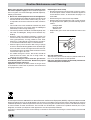
Consigli pratici per l’uso dei bruciatori
Al fine di ottenere il massimo rendimento è utile ricordare
quanto segue:
• utilizzare recipienti adeguati a ciascun bruciatore (ve-
dere tabella) alfine di evitare che le fiamme fuoriescano
dal fondo dei recipienti.
• utilizzare solamente recipienti a fondo piatto.
Consigli pratici per la cottura
Nella cottura al forno utilizzate una sola leccarda o griglia
alla volta. Questa va posizionata sulle guide inferiori o su-
periori a seconda che la cottura necessiti di maggior ca-
lore dal basso o dall’alto.
Preriscaldamento
Nel caso in cui sia necessario preriscaldare il forno, in
linea di massima tutte le volte in cui si cuociono cibi lievi-
tati, è consigliabile utilizzare la funzione “forno statico” che
consente di raggiungere la temperatura in breve tempo.
Alla fine del preriscaldamento, indicata dallo spegnimen-
to della spia rossa “O”, selezionate la funzione di cottura
più indicata.
Cottura del pesce e della carne
Per le carni bianche, i volatili ed il pesce utilizzate tempe-
rature da 180 °C a 200 °C.
Per le carni rosse che si vuole siano ben cotte all’esterno
conservando all’interno il sugo, è bene utilizzare una tem-
peratura iniziale alta (200°C-220°C) per breve tempo, per
poi diminuirla successivamente.
In generale, più grosso è l’arrosto, più bassa dovrà esse-
re la temperatura e più lungo il tempo di cottura. Ponete la
carne da cuocere al centro della griglia ed inserite sotto
la griglia la leccarda per raccogliere i grassi.
Inserite la griglia in modo che il cibo si trovi al centro del
forno. Se volete più calore da sotto, utilizzate i ripiani più
bassi. Per ottenere arrosti saporiti (in particolare anatra e
selvaggina) bardate la carne con lardo o pancetta e posi-
zionatela in modo che sia nella parte superiore.
Cottura dei dolci
Nella cottura dei dolci preriscaldate sempre il forno e, per
evitare un abbassamento del dolce, non aprite la porta
durante la cottura. In generale:
Dolce troppo secco
La prossima volta impostate una temperatura di10°C
superiore e riducete il tempo di cottura.
Dolce si abbassa
Usate meno liquido o abbassate la temperatura di
10°C.
Dolce scuro superiormente
Inseritelo ad altezza inferiore, impostate una
temperatura più bassa e prolungate la cottura.
Buona cottura esterna, ma interno colloso
Usate meno liquido, riducete la temperatura,
aumentate il tempo di cottura.
Dolce non si stacca dallo stampo
Ungete bene lo stampo e cospargetelo anche con un
pò di farina.
Utilizzo del grill
Utilizzate la funzione
“grill” posizionando il cibo al
centro della griglia (posta al 3° o 4° ripiano partendo dal
basso), dato che risulta accesa solamente la parte cen-
trale della resistenza superiore.
Utilizzare il primo ripiano dal basso, posizionandoci la
leccarda in dotazione per raccogliere sughi e/o grassi.
Quando si utilizza tale funzione, si raccomanda di impo-
stare il termostato al massimo. Questo, però, non signifi-
ca che non si possano utilizzare temperature inferiori, sem-
plicemente regolando la manopola del termostato sulla
temperatura desiderata.
Importante: effettuare la cottura al grill con porta del
forno chiusa, ciò per ottenere migliori risultati ed un sen-
sibile risparmio di energia (10% circa).
Pertanto i migliori risultati nell’utilizzo delle funzioni
grill si ottengono disponendo la griglia sugli ultimi
ripiani partendo dal basso (vedi tabella cottura)
dopodiché, per raccogliere i grassi ed evitare la for-
mazione di fumo, disponete la leccarda in dotazione
nel primo ripiano dal basso.
• al momento dell’ebollizione ruotare la manopola fino
alla posizione di minimo.
• utilizzare sempre recipienti con coperchio.
Bruciatore ø Diametro recipienti (cm)
Rapido (R) 24 – 26
Semi Rapido (S) 16 – 20
Ausiliario (A) 10 – 14
N.B. Sui modelli dotati di griglietta di riduzione, quest’ulti-
ma dovrà essere utilizzata solo per il bruciatore ausiliario,
quando si utilizzano dei recipienti di diametro inferiore a
12 cm.

10
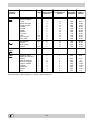
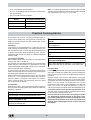
Posizione
manopola
selezione
Cibo da cucinare Peso
(Kg)
Posizione di
cottura ripiani
dal basso
Tempo di pre-
riscaldamento
(minuti)
Posizione
manopola
termostato
Tempo di
cottura
(minuti)
1 Statico
Anatra
Arrosto di vitello o
manzo
Arrosto di maiale
Biscotti (di frolla)
Crostate
Lasagne
Agnello
Sgombro
Plum-cake
Bignè
Pan di spagna
Torte salate
1
1
1
-
1
1
1
1
1
0.3
0.5
1.5
3
3
3
3
3
3
2
2
2
3
3
3
15
15
15
15
15
10
10
10
10
10
10
15
200
200
200
180
180
190
180
180
170
180
170
200
65-75
70-75
70-80
15-20
30-35
35-40
50-60
30-35
40-50
30-35
20-25
30-35
2 Forno Dolce
Torte lievitate
Crostate
Torte di frutta
Brioches
0,5
1
1
0,5
3
3
3
3
15
15
15
15
160
180
180
160
30-40
35-40
50-60
25-30
3 Forno
Sopra
Ritocchi di cottura - 3/4 15 220 -
4 Grill
Sogliole e seppie
Spiedini di calamari e
gamberi
Filetto di merluzzo
Verdure alla griglia
Bistecca di vitello
Cotolette
Hamburger
Sgombri
Toast
1
1
1
1
1
1
1
1
n.° 4
4
4
4
3/4
4
4
4
4
4
5
5
5
5
5
5
5
5
5
Max
Max
Max
Max
Max
Max
Max
Max
Max
8-10
6-8
10
10-15
15-20
15-20
7-10
15-20
2-3
NB:
i tempi di cottura sono indicativi e possono essere modificati in base ai propri gusti personali. Nelle cotture al
grill la leccarda va posta sempre al 1° ripiano a partire dal basso.

11
Manutenzione ordinaria e pulizia della cucina
Prima di ogni operazione disinserire elettricamente la
cucina. Per una lunga durata della cucina è indispensabile
eseguire frequentemente una accurata pulizia generale,
tenendo presente che:
• per la pulizia non utilizzare apparecchi a vapore
• le parti smaltate e i pannelli autopulenti, se presenti,
vanno lavate con acqua tiepida senza usare polveri
abrasive e sostanze corrosive che potrebbero rovinar-
le;
• l’interno del forno va pulito, con una certa frequenza,
quando è ancora tiepido usando acqua calda e deter-
sivo, risciacquando ed asciugando poi accuratamen-
te;
• gli spartifiamma vanno lavati frequentemente con ac-
qua calda e detersivo avendo cura di eliminare le
incrostazioni;
• l’acciaio inox può rimanere macchiato se rimane a con-
tatto per lungo tempo con acqua fortemente calcarea
o con detergenti aggressivi (contenenti fosforo). Si con-
siglia di sciacquare abbondantemente ed asciugare
dopo la pulizia. E’ inoltre opportuno asciugare even-
tuali trabocchi d’acqua.
• Pulire il vetro della porta con spugne e prodotti non
abrasivi e asciugare con un panno morbido; non usare
materiali ruvidi abrasivi o raschietti metallici affilati che
possono graffiare la superficie e causare la frantuma-
zione del vetro.
• nei modelli dotati di coperchio in cristallo la pulizia si
effettua con acqua calda evitando l’impiego di panni
ruvidi o sostanze abrasive.
N.B.: evitare di chiudere il coperchio fino a che i bru-
ciatori gas sono ancora caldi. Eliminare eventuali li-
quidi presenti sul coperchio prima di aprirlo.
Importante: controllare periodicamente lo stato di conser-
vazione del tubo flessibile di collegamento gas e sostituir-
lo non appena presenta qualche anomalia; è consigliabile
la sostituzione annuale.
Sostituzione della lampada nel vano forno
• Togliere l’alimentazione al forno tramite l’interruttore
omnipolare utilizzato per il collegamento del forno al-
l’impianto elettrico, o scollegare la spina, se accessi-
bile;
• Svitare il coperchio in vetro del portalampada;
• Svitare la lampada e sostituirla con una resistente ad
alta temperatura (300°C) con queste caratteristiche:
- Tensione 230V
- Potenza 25W
- Attacco E14
• Rimontare il coperchio in vetro e ridate alimentazione
al forno.
Manutenzione rubinetti gas
Con il tempo può verificarsi il caso di un rubinetto che si
blocchi o presenti difficoltà nella rotazione, pertanto sarà
necessario provvedere alla sostituzione del rubinetto stes-
so.
N.B.: Questa operazione deve essere effettuata da un
tecnico autorizzato dal costruttore.
La direttiva Europea 2002/96/CE sui rifiuti di apparecchiature elettriche ed elettroniche (RAEE), prevede che gli elettro-
domestici non debbano essere smaltiti nel normale flusso dei rifiuti solidi urbani. Gli apparecchi dismessi devono essere
raccolti separatamente per ottimizzare il tasso di recupero e riciclaggio dei materiali che li compongono ed impedire
potenziali danni per la salute e l’ambiente. Il simbolo del cestino barrato è riportato su tutti i prodotti per ricordare gli
obblighi di raccolta separata.
Per ulteriori informazioni, sulla corretta dismissione degli elettrodomestici, i detentori potranno rivolgersi al servizio
pubblico preposto o ai rivenditori.

12
Important
1 This appliance is intended for non-professional use within the home.
2 These instructions are only for those countries whose symbols appear in
the booklet and on the serial no. plate of the appliance.
3 This owner’s manual is for a class 1 appliance (insulated) or
class 2, subclass 1 appliances (installed between two cabi-
nets.
4 Before using your appliance, read the instructions in this owner’s manual
carefully since it provides all the information you need to ensure safe
installation, use and maintenance. Always keep this owner’s manual close
to hand since you may need to refer to it in the future.
5 When you have removed the packing, check that the appliance is not
damaged. If you have any doubts, do not use the appliance and contact
your nearest Ariston Service Centre. Never leave the packing components
(plastic bags, polystyrene foam, nails, etc.) within the reach of children
since they are a source of potential danger.
6 The appliance must be installed only by a qualified technician in compliance
with the instructions provided. The manufacturer declines all liability for
improper installation, which may result in personal injury and damage to
property.
7 The electrical safety of this appliance can only be guaranteed if it is cor-
rectly and efficiently earthed, in compliance with regulations on electrical
safety. Always ensure that the earthing is efficient. If you have any doubts,
contact a qualified technician to check the system. The manufacturer
declines all liability for damage resulting from a system which has not been
earthed.
8 Before plugging the appliance into the mains, check that the specifications
indicated on the date plate (on the appliance and/or packaging) correspond
with those of the electrical and gas systems in your home.
9 Check that the electrical capacity of the system and sockets will support
the maximum power of the appliance, as indicated on the data plate. If you
have any doubts, contact a qualified technician.
10 An omnipolar switch with a contact opening of at least 3 mm or more is
required for installation.
11 If the socket and appliance plug are not compatible, have the socket
replaced with a suitable model by a qualified technician, who should also
check that the cross-section of the socket cable is sufficient for the power
absorbed by the appliance. The use of adaptors, multiple sockets and/or
extensions, is not recommended. If their use cannot be avoided, remember
to use only single or multiple adapters and extensions which comply with
current safety regulations. In these cases, never exceed the maximum
current capacity indicated on the individual adaptor or extension and the
maximum power indicated on the multiple adapter.
12 Do not leave the appliance plugged in if it is not in use. Switch off the main
switch and gas supply when you are not using the appliance.
13 The openings and slots used for ventilation and heat dispersion must never
be covered.
14 The user must not replace the supply cable of this appliance. Always
contact an after-sales service centre which has been authorised by the
manufacturer if the cable has been damaged or needs replacement.
15 This appliance must be used for the purpose for which it was expressly
designed. Any other use (e.g. heating rooms) is considered to be improper
and consequently dangerous. The manufacturer declines all liability for
damage resulting from improper and irresponsible use.
16 A number of fundamental rules must be followed when using electrical
appliances. The following are of particular importance:
• Do not touch the appliance when your hands or feet are wet.
• Do not use the appliance barefooted.
• Do not use extensions, but if they are necessary, caution must be
exercised.
• Never pull the power supply cable or the appliance to unplug the
appliance plug from the mains.
• Never leave the appliance exposed to atmospheric agents (rain, sun
etc.)
• Do not allow children or persons who are not familiar with the appliance
to use it, without supervision.
17 Always unplug the appliance from the mains or switch off the main switch
before cleaning or carrying out maintenance.
18 In the case of problems and/or faulty operation, switch off the appliance,
close the gas cock and do not tamper with the appliance. For repairs,
contact only authorised after-sales service centres and request the use of
original spare parts only. Failure to comply with the above may compromise
the safety of the appliance.
19 If you are no longer using an appliance of this type, remember to make it
unserviceable by unplugging the appliance from the mains and cutting the
supply cable. Also make all potentially dangerous parts of the appliance
safe, above all for children who could play with the appliance.
20 To avoid accidental spillage do not use cookware with uneven or deformed
bottoms on the burners or on the electric plates. Turn the handles of pots
and pans inwards to avoid knocking them over accidentally.
21 Some parts of the appliance, in particular the hot plates, remain heated for
a long time after use. Make sure not to touch them.
22 Never use flammable liquids such as alcohol or gasoline, etc. near the
appliance when it is in use.
23 When using small electric appliances near the hob, keep the supply cord
away from the hot parts.
24 Make sure the knobs are in the “•”/”¡” position when the appliance is not in
use.
25 When the appliance is in use, the heating elements and
some parts of the oven door become extremely hot. Make
sure you don't touch them and keep children well away.
26 Gas appliances require regular air exchange to ensure trou-
ble-free performance. When installing the cooker, follow the
instructions provided in the paragraph on “Positioning” the
appliance.
27 The glass top (only on certain models) can shatter if it is overheated.
Therefore, all of the burners or hot plates must be turned off before the top
is closed.
28 If the cooker is placed on a pedestal, take the necessary precautions to
prevent the same from sliding off the pedestal itself.
29 The internal surfaces of the compartment (where present) may become
hot.
To maintain the EFFICIENCY and SAFETY of this appliance, we recommend:
• call only the Service Centers authorized by the manufacturer
• always use original Spare Parts

13
Installation Instructions
The following instructions should be read by a qualified tech-
nician to ensure that the appliance is installed, regulated and
serviced correctly in compliance with current standards.
Important: Remember to unplug the appliance from the
mains before making adjustments or doing maintenance.
Positioning
Important: This unit may be installed and used only in per-
manently ventilated rooms in compliance with current Na-
tional Regulations. The following requirements must be ob-
served:
a) The room must be equipped with an exhaust system that
vents the combustion fumes to the outside. It may con-
sist of a hood or an electric fan that automatically starts
each time the appliance is turned on.
Flue or Branched Flue System Directly to the Outside
(only for cooking appliances)
b) The room must also have a system to permit proper air
circulation, needed for combustion to occur normally. The
flow of air needed for combustion must not be less than 2
m
3
/h per kW of installed power. The air circulation system
may take air directly from the outside by means of a pipe
with an inner cross section of at least 100 cm
2
; the open-
ing must not be able to be accidentally blocked. For those
appliances not equipped with a safety device for acciden-
tal flame loss, the ventilation apertures must be increased
by 100%, with the minimum being 200cm
2
(Fig. A). The
system can also provide the air needed for combustion
by indirect means, i.e. from adjacent rooms fitted with air
circulation tubes as described above. However, these
rooms must not be common rooms or bedrooms. (Fig. B)
.
Detail A Adjacent Room to
Room be Ventilated
A
Examples of Ventilation Openings Increased Opening Between
Comburent Air Door and Floor
Fig. A Fig. B
c) Intensive and prolonged use of the appliance may result
in the need for supplemental air circulation, e.g. opening
windows or increasing mechanical venting (if present).
d) Liquified petroleum gas is heavier than the air and, there-
fore, settles downwards. Thus, rooms containing LPG
cylinders must also be equipped with apertures to the
outside for ventilation of gas in the case of leaks. LPG
cylinders must not, therefore, be installed or stored in
rooms or storage areas that are below ground level (cel-
lars, etc.) whether they are partially or completely full. It
is a good idea to keep only the cylinder being used in the
room, positioned so that it is not subject to heat produced
by external sources (ovens, fireplaces, stoves, etc. )
which are able to increase the temperature of the cylinder
above 50°C.
Levelling Your Appliance (only on certain models)
4 support feet which are adjusted using screws are located
in the lower part of the cooker. These level off the oven
when necessary. It is essential that the cooker be standing
level.
Mounting the legs (only on certain models)
Press-fit legs are supplied which fit under the base of your
cooker.
Installing the Cooker
The appliance can be installed next to furniture units which
are no taller than the top of the cooker hob. The wall in
direct contact with the back panel of the cooker must be
made of non-flammable material. During operation the back
panel of the cooker could reach a temperature of 50°C
above room temperature. For proper installation of the
cooker, the following precautions must be taken:
a) Kitchen cabinets installed next to the cooker that are higher
than the top of the hob, must be at least 600 mm from the
edge of the hob itself.
b) Hoods must be installed according to the requirements in
the installation manual for the hood and, in any case, at a
minimum height of 650 mm.
c) If the hood is installed below a wall cabinet, the latter
must be at least 700 mm (millimetres) above the surface
of the hob. Cabinets installed adjacent to the hood must
be at least 420 mm above the hob, as shown in Figures
C and D.

14
HOOD
420
Min.
min. 650 mm. with hood
min.
700 mm. without hood
mm.
600
Min. mm.
420
Min. mm.
HOOD
900
Min. mm.
420
Min.
min.
650
mm. with hood
min.
700
mm. without hood
mm.
420
Min. mm.
Fig. C Fig. D
Making the Gas Connection
T
he appliance should be connected to the mains or to a gas
cylinder in compliance with current National Regulations.
Before making the connection, check that the cooker is regu-
lated for the gas supply you are using. If not, follow the in-
structions indicated in the paragraph “Converting to Different
Types of Gas." On some models the gas supply can be con-
nected on the left or on the right, as necessary; to change
the connection, reverse the position of the hose holder with
that of the cap and replace the gasket (supplied with the
appliance). When using liquid gas from a cylinder, install a
pressure regulator which complies with the current National
Regulations.
Important: Check that the supply pressure complies with
the values indicated in table 1 “Burner and Nozzle Character-
istics” since this will ensure safe operation, correct consump-
tion and ensure a longer life for your appliance.
Connection with a Hose
Make the connection using a gas hose that complies with
requirements set forth by the current National Regulations.
The inner diameters of the pipe are as follows:
- 8 mm for liquid gas;
- 13 mm for methane.
When installing the hose, remember to take the following
precautions:
• No part of the hose must come into contact with parts
whose temperature exceeds 50°C;
• The length of the hose should be less than 1500 mm;
• The hose should not be subject to twisting or pulling, and
should not have bends or kinks;
• The hose should not touch objects with sharp edges,
corners or moving parts, and it should not be crushed;
• The full length of the hose should be easy to inspect in
order to check its condition.
Check that the hose fits firmly into place at the two ends and
fix it with clamps complying with current National Regula-
tions. If any of the above recommendations can not be fol-
lowed, flexible metal pipes should be used. If the cooker is
installed in compliance with the requirements for class 2,
subclass 1, it is highly recommended that the gas con-
nection be made with a flexible metal pipe in compliance
with current safety standards.
Connecting a Flexible, Jointless, Stainless Steel Pipe
to a Threaded Attachment
Remove the hose holder fitted on the appliance. The gas
supply pipe fitting is a threaded 1/2 gas cylindrical male at-
tachment. Use only pipes and seals that comply with current
National Regulations. The full length of the pipe when in-
stalled must not exceed 2000 mm.
Checking the Seal
Important: Once the installation has been completed, check
to make sure that the seals on all the connections are tight,
using a soapy solution (never a flame). After the connection
has been made, make sure that the flexible metal pipe does
not come into contact with moveable parts and that it is not
crushed.
Connecting the Power Supply Cord to the Mains
Install a normalised plug corresponding to the load indicated
on the data plate. When connecting the cable directly to the
mains, install an omnipolar circuit-breaker with a minimum
contact opening of 3 mm between the appliance and the mains.
The omnipolar circuit breaker should be sized according to
the load and should comply with current regulations (the earth
wire should not be interrupted by the circuit breaker). The
supply cable should be positioned so that it does not reach a
temperature of more than 50°C with respect to the room tem-
perature, along its length. Before making the connection,
check that:
• The limiter valve and the home system can support the
appliance load (see data plate);
• The mains are properly earthed in compliance with cur-
rent safety standards and regulations;
• There is easy access to the socket and omnipolar circuit
breaker, once the hob has been installed.
N.B.: Never use reducers, adaptors or shunts since they can
cause heating or burning.
Converting the Cooker to Different Types of Gas
In order to convert the cooker for use with a type of gas
different than the one for which it was factory set (indicated
on the label attached to the lid), the following steps must be
taken:
a) Replace the hose holder mounted on the appliance with
that supplied in the bag of “cooker accessories.”
Important: The hose holder for liquid gas is marked 8, the
hose holder for methane and city gas is marked 13. In any
case, always use a new sealing gasket.
b) Replace the burner nozzles on the hob:
• Remove the grids and slide the burners from their housings;
• Unscrew the nozzles using a 7 mm socket spanner, and
replace them with nozzles for the new type of gas (see
table 1 “Burner and Nozzle Characteristics”).
• Replace all the components by repeating the steps in
reverse order.
c) Minimum regulation of the hob burners:

15
•
Turn the tap to minimum;
• Remove the knob and adjust the regulation screw, which
is positioned in or next to the tap pin, until the flame is
small but steady.
N.B.: In the case of liquid gas, the regulation screw
must be screwed in all the way.
• Check that the flame does not go out when you turn the
tap quickly from high to low.
d) Regulating the primary air of the burners: The primary air
of the burners does not need to be regulated.
Important
Burner and Nozzle Characteristics
Table 1 Liquid Gas Natural Gas
Burner Diamet-
er
(mm)
Thermal Power
kW (p.c.s.*)
By-Pass
1/100
Nozzle
1/100
Flow*
g/h
Nozzle
1/100
Flow*
l/h
Nominal Reduced (mm) (mm) *** ** (mm)
Fast
(Large)(R)
100 3.00 0.7 41 86 218 214 116 286
Semi Fast
(Medium)(S)
75 1.90 0.4 30 70 138 136 106 181
Auxiliary
(Small)(A)
55 1.00 0.4 30 50 73 71 79 95
Supply
Pressures
Nominal (mbar)
Minimum (mbar)
Maximum (mbar)
28-30
20
35
37
25
45
20
17
25
* At 15°C and 1013 mbar- dry gas
** Propane P.C.S. = 50,37 MJ/Kg
*** Butane P.C.S. = 49,47 MJ/Kg
Natural P.C.S. = 37,78 MJ/m
3
S
S
R
A
K6G11S/I
On completion of this operation, replace the old rating sticker
with one indicating the new type of gas used. This sticker is
available from our Service Centres.
Note
Should the pressure of the gas used be different (or vary)
from the recommended pressure, an appropriate pressure
regulator must be installed on the inlet pipe (in compliance
with current National Regulations relative to “regulators for
piped gas”).

16
Technical Characteristics
Inner dimensions of the oven:
Width: 43,5 cm
Depth: 43 cm
Height: 32 cm
Inner Volume of the Oven:
litri 60
Innder dimensions of the plate plate warmer:
Width: 46 cm
Depth: 42 cm
Height: 8.5 cm
ENERGY LABEL
Directive 2002/40/EC on the label of electric ovens
Norm EN 50304
Declared energy consumption for Natural convection Class
heating mode: Convection
Voltage and Frequency of Power Supply:
see data plate
Burners:
adaptable for use with all the types of gas indicated on
the data plate
This appliance conforms with the following European
Economic Community directives:
- 73/23/EEC of 19/02/73 (Low Voltage) and subsequent
modifications;
- 89/336/EEC of 03/05/89 (Electromagnetic Compatibility)
and subsequent modifications;
- 90/396/EEC of 29/06/90 (Gas) and subsequent
modifications;
- 93/68/EEC of 22/07/93 and subsequent modifications.
Cooker with electric oven
H
A Tray for Catching Overflows
B Gas Burner
D Top Grate
E Control Panel
F Adjustable Feet or Legs
G Dripping Pan or Baking Sheet
H Safety Device for Hob Burners
K Oven Rack
L Selector Knob
M Thermostat Knob
N Control Knobs for Gas Burners on Hob
O Thermostat Light
S Timer Knob
F
A
E
K
G
D
B
O
LMS N

17
How To Use Your Appliance
The various functions featured with the oven are control-
led using the knobs and buttons on the control panel.
Notice: Before operating the product, remove all plastic
film from the sides of the appliance.
Control Knobs for the Gas Burners on the Hob (N)
The position of the gas burner controlled by each one of the
knobs is shown by a symbol of a solid ring:
• . To light one of
the burners, hold a lighted match or lighter near the burner
and, at the same time, press down and turn the correspond-
ing knob in the counter-clockwise direction to the maximum
setting. Each burner can be operated at its maximum,
minimum or intermediate power. Shown on the knob are the
different symbols for off
• (the knob is on this setting when
the symbol lines up with the reference mark on the control
panel), for maximum
and minimum .
To obtain these settings, turn the knob counter-clockwise
with respect to the off position. To turn off the burner, turn the
knob clockwise until it stops (corresponding again with the
•
symbol).
Models with Hob Gas Burner Safety Devices to
Prevent Leaks
These models can be identified by the presence of the de-
vice itself (see detail H).
Important: Since the hob burners are equipped with a
safety device, you must hold the control knob in for about
3 seconds after the burner has been lighted to allow the
gas to pass until the safety thermocouple has heated.
Notice: The first time you use your appliance, we recom-
mend that you set the thermostat to the highest setting
and leave the oven on for about half an hour with nothing
in it, with the oven door shut. Then, open the oven door
and let the room air. The odour that is often detected dur-
ing this initial use is due to the evaporation of substances
used to protect the oven during storage and until it is in-
stalled.
Attention: Only use the bottom shelf of the oven when
using the rotisserie to cook (where present). For all other
types of cooking, never use the bottom shelf and never
place anything on the bottom of the oven when it is in
operation because this could damage the enamel. Always
place your cookware (dishes, aluminium foil, etc. etc.) on
the grate provided with the appliance inserted especially
along the oven guides.
Convection Mode
Position of thermostat knob “M”: between 60°C and Max.
On this setting, the top and bottom heating elements come
on. This is the classic, traditional type of oven which has
been perfected, with exceptional heat distribution and reduced
energy consumption. The convection oven is still unequalled
when it comes to cooking dishes made up of several ingredi-
ents, e.g. cabbage with ribs, Spanish style cod, Ancona style
stockfish, tender veal strips with rice, etc. Excellent results
are achieved when preparing veal or beef-based dishes as
well (braised meats, stew, goulash, wild game, ham etc.)
which need to cook slowly and require basting or the addition
of liquid. It nonetheless remains the best system for baking
cakes as well as fruit and cooking using covered casserole
dishes for oven baking. When cooking in convection mode,
only use one dripping pan or cooking rack at a time, other-
wise the heat distribution will be uneven. Using the different
rack heights available, you can balance the amount of heat
between the top and the bottom of the oven. Select from
among the various rack heights based on whether the dish
needs more or less heat from the top.
Pastry Mode
Position of thermostat knob “M”: Between 60°C and Max.
The bottom heating element comes on.
This mode is ideal for baking and cooking delicate foods -
especially cakes that need to rise because the heat coming
from the bottom helps the leavening process.
Please note that it takes a considerable amount of time for
the higher temperatures to be reached, therefore we recom-
mend you use the “Convection Mode” in these cases.
“Top” Oven
Position of thermostat knob “M”: Between 60°C and Max.
The top heating element comes on.
This mode can be used to brown food at the end of cooking.
Grill
Position of thermostat knob “M”: Max
The top central heating element comes on.
The extremely high and direct temperature of the grill makes
it possible to brown the surface of meats and roasts while
locking in the juices to keep them tender. The grill is also
highly recommended for dishes that require a high tempera-
ture on the surface: beef steaks, veal, rib steak, filets, ham-
burgers etc...
Some grilling examples are included in the “Practical Cook-
ing Advice” paragraph.
The oven light
Set knob “L” to the
symbol to turn it on. It lights the oven
and stays on when any of the electrical heating elements in
the oven come on.
Thermostat Light (O)
This light indicates that the oven is heating. When it turns off,
the temperature inside the oven has reached the setting made
with the thermostat knob. At this point, the light will turn on
and off as the oven maintains the temperature at a constant
level.
Timer Knob (S)
In order to use the timer, it must be wound by turning the
"S" knob almost one complete turn in the clockwise direc-
tion
. Then, turning it back , set the desired time by
lining up the number for the minutes with the mark on the
control panel.
Practical Advice on Using the Burners
To use the burners as efficiently as possible, some basic
guidelines should be followed:
• Use cookware that is the right size for each burner (see
table) in order to prevent the flame from spreading be-
yond the bottom of the cookware.

18
• Only use cookware with flat bottoms.
• As soon as the boiling point is reached, turn the knob to
the lowest setting.
• Always use lids with pots and pans.
Burner ø Cookware diameter (cm)
Fast (R) 24 - 26
Semi Fast (S) 16 - 20
Auxiliary (A) 10 - 14
Practical Cooking Advice
W en cooking in the oven, use only one dripping pan or
rack at a time. Select from among the top or bottom rack
heights based on whether the dish needs more or less
heat from the top.
Preheating
If the oven must be preheated (this is generally the case
when cooking leavened foods), we recommend you use
the “convection mode” to reach the desired temperature
as quickly as possible. When preheating is over, which is
indicated by the red light “O” going out, select the required
cooking mode.
Cooking Fish and Meat
When cooking white meat, fowl and fish, use temperature
settings from 180 °C to 200 °C.
For red meat that should be well done on the outside while
tender and juicy in the inside, it is a good idea to start with
a high temperature setting (200°C-220°C) for a short time,
then turn the oven down afterwards.
In general, the larger the roast, the lower the temperature
setting. Place the meat on the centre of the grid and place
the dripping pan beneath it to catch the fat.
Make sure that the grid is inserted so that it is in the centre
of the oven. If you would like to increase the amount of
heat from below, use the low rack heights. For savoury
roasts (especially duck and wild game), dress the meat
with lard or bacon on the top.
Baking Cakes
When baking cakes, always preheat the oven and do not
open the oven door during baking to prevent the cake from
dropping. In general:
Pastry dropped
Use less liquid or lower the temperature by 10°C.
Pastry is too dark on top
Place it on a lower rack, lower the temperature, and
increase the cooking time.
Cooked well on the inside but sticky on the
outside
Use less liquid, lower the temperature, and increase
the cooking time.
The pastry sticks to the pan
Grease the pan well and sprinkle it with a dusting of
flour.
I used more than one level and they are not all at
the same cooking point
Use a lower temperature setting. It is not necessary to
remove the food from all the racks at the same time.
Using the Grill
Use the
“Grill” mode, placing the food under the centre
of the grill (situated on the 3rd or 4th rack form the bottom)
because only the central part of the top heating element is
turned on.
Use the bottom rack (1st from the bottom), placing the
dripping pan provided to collect any sauce and/or grease
and prevent the same from dripping onto the oven bottom.
When using this mode, we recommend you set the
thermostat to the highest setting. However, this does not
mean you cannot use lower temperatures, simply by
adjusting the thermostat knob to the desired temperature.
Important: always use the grill with the oven door shut.
This will allow you both to obtain excellent results and to
save on energy (approximately 10%).
Therefore the best results when using the grill modes
are obtained by placing the grid on the lower racks
(see cooking table) then, to prevent fat and grease from
dripping onto the bottom of the oven and smoke from
forming, place a dripping-pan on the 1st oven rack from
the bottom.
N.B.: On models equipped with a reduction grid, the grid
should only be used with the auxiliary burner when cookware
with a diameter of less than 12 cm is used.

19
Selector knob
setting
Food to be cooked Weight
(in kg)
Cooking rack
position from
bottom
Preheating time
(minutes)
Thermostat
knob
setting
Cooking
time
(minutes)
1 Convection
Duck
Roast veal or beef
Pork roast
Biscuits (short pastry)
Tarts
Lasagne
Lamb
Mackerel
Plum-cake
Cream puffs
Sponge-cake
Savoury pies
1
1
1
-
1
1
1
1
1
0.3
0.5
1.5
3
3
3
3
3
3
2
2
2
3
3
3
15
15
15
15
15
10
10
10
10
10
10
15
200
200
200
180
180
190
180
180
170
180
170
200
65-75
70-75
70-80
15-20
30-35
35-40
50-60
30-35
40-50
30-35
20-25
30-35
2 Pastry
Mode
Raised Cakes
Tarts
Fruit cakes
Brioches
0,5
1
1
0,5
3
3
3
3
15
15
15
15
160
180
180
160
30-40
35-40
50-60
25-30
3 Top Oven
Browning food to
perfect cooking
- 3/4 15 220 -
4 Grill
Soles and cuttlefish
Squid and prawn
kebabs
Cod filet
Grilled vegetables
Veal steak
Cutlets
Hamburgers
Mackerels
Toasted sandwiches
1
1
1
1
1
1
1
1
n.° 4
4
4
4
3/4
4
4
4
4
4
5
5
5
5
5
5
5
5
5
Max
Max
Max
Max
Max
Max
Max
Max
Max
8-10
6-8
10
10-15
15-20
15-20
7-10
15-20
2-3
NB:
cooking times are approximate and may vary according to personal taste. When cooking using the grill, the
dripping pan must always be placed on the 1st oven rack from the bottom.

20
Routine Maintenance and Cleaning
Before each operation, disconnect the appliance from
the electrical power supply. To ensure that the appliance
lasts a long time, it must be thoroughly cleaned frequently,
keeping in mind that:
••
••
• Do not use steam equipment to clean the appliance.
• The enamelled parts and the self-cleaning panels should
be washed with warm water, without using any abra-
sive powders or corrosive substances which could ruin
them;
• The inside of the oven should be cleaned fairly often
while it is still warm, using warm water and detergent
followed by careful rinsing and drying;
• The flame spreaders should be washed frequently with
hot water and detergent, taking care to eliminate any
buildup;
• Stainless steel may become marked if it comes into
contact with very hard water or harsh detergents (con-
taining phosphorous) for long periods of time. After
cleaning, it is advisable to rinse thoroughly and dry. It
is also recommended that drops of water be dried.
• Clean the glass part of the oven door using a sponge
and a non-abrasive cleaning product, then dry thoroughly
with a soft cloth. Do not use rough abrasive material or
sharp metal scrapers as these could scratch the surface
and cause the glass to crack.
• On models with glass covers, the covers should be
cleaned with hot water; the use of rough cloths or
abrasives is to be avoided.
N.B.: Avoid closing the cover while the gas burners
and electric plates are still warm. Remove any liquid
from the lid before opening it.
Important: Periodically check the wear of the gas hose
and substitute it if there are any defects; we recommend
changing it every year.
Replacing the Oven Lamp
• Disconnect the oven from the power supply by means
of the omnipolar switch used to connect the appliance
to the electrical mains; or disconnect the plug if it is
accessible.
• Remove the glass cover of the lamp-holder.
• Remove the lamp and replace it with a lamp resistant
to high temperatures (300°C) with the following specifi-
cations:
- Voltage: 230V
- Wattage: 25W
- Socket: E14
• Replace the glass cover and connect the oven to the
mains.
Gas tap maintenance
The taps may jam in time or they may become difficult to
turn. If so, the tap itself must be replaced.
N.B.: This operation must be performed by a technician
authorised by the manufacturer.
The European Directive 2002/96/EC on Waste Electrical and Electronic Equipment (WEEE), requires that old household
electrical appliances must not be disposed of in the normal unsorted municipal waste stream. Old appliances must be
collected separately in order to optimise the recovery and recycling of the materials they contain and reduce the impact
on human health and the environment. The crossed out “wheeled bin” symbol on the product reminds you of your
obligation, that when you dispose of the appliance it must be separately collected.
Consumers should contact their local authority or retailer for information concerning the correct disposal of their old
appliance.
La pagina si sta caricando...
La pagina si sta caricando...
La pagina si sta caricando...
La pagina si sta caricando...
-
 1
1
-
 2
2
-
 3
3
-
 4
4
-
 5
5
-
 6
6
-
 7
7
-
 8
8
-
 9
9
-
 10
10
-
 11
11
-
 12
12
-
 13
13
-
 14
14
-
 15
15
-
 16
16
-
 17
17
-
 18
18
-
 19
19
-
 20
20
-
 21
21
-
 22
22
-
 23
23
-
 24
24


Indesit K6G11S(W)/I Guida utente
- Categoria
- Piani cottura
- Tipo
- Guida utente
in altre lingue
- English: Indesit K6G11S(W)/I User guide
Documenti correlati
Altri documenti
-
Whirlpool C 67S P2 X I Guida utente
-
 Euro-Kitchen SPAGNA VETRO 218 Series Manuale del proprietario
-
-
-
-
-
-
Whirlpool C 649 P.4 (A) I Guida utente
-
-
