
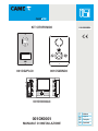
001CS2PLC0 001CS2BNC0
001DC002AC
M2M1
+–
001CK0001
MANUALE DI INSTALLAZIONE
IT
Italiano
EN
English
FR
Français
RU
Pусский
FA00955M04
KIT CITOFONICO

135
99 30
3.5
6.5
243
207
135
99 30
3.5
6.5
243
207
Pag. 2 - Manuale FA00955-IT - ver. 1 - 11/2017 - © CAME S.p.A. - I contenuti del manuale sono da ritenersi suscettibili di modifica in qualsiasi momento senza obbligo di preavviso.
Avvertenze generali
All'apertura dell'imballo
• Leggere attentamente le istruzioni, prima di iniziare l’installazione ed eseguire gli interventi come specificato dal costruttore;
• Dopo aver tolto l’imballaggio assicurarsi dell’integrità dell’apparecchio;
• Gli elementi dell’imballaggio (sacchetti in plastica, polistirolo espanso, ecc.) non devono essere lasciati alla portata dei bambini in quanto potenziali fonti di pericolo;
Indicazioni generali per l'installazione
• L’installazione, la programmazione, la messa in servizio e la manutenzione del prodotto deve essere effettuata soltanto da personale tecnico qualificato ed opportu-
namente addestrato nel rispetto delle normative vigenti ivi comprese le osservanze sulla prevenzione infortuni;
• Operare in ambienti sufficientemente illuminati e idonei per la salute e utilizzare strumenti, utensili ed attrezzature in buono stato;
• Il dispositivo va installato conformemente al grado IP indicato nelle caratteristiche tecniche;
• Se sono previsti, non ostruire le aperture o i fori di ventilazione o per l’eliminazione del calore;
Collegamento elettrico dei dispositivi
• L’impianto elettrico dovrà essere realizzato in conformità con le normative in vigore nel paese di installazione;
• Prima di collegare gli apparecchi, controllare che le indicazioni riportate sulla piastra corrispondano a quelle della rete elettrica;
• Proteggere gli apparecchi alimentati con tensione di rete mediante un interruttore di rete onnipolare con una separazione dei contatti di almeno 3 mm;
• I conduttori dei cablaggi non utilizzati devono essere isolati.
• Per evitare i contatti accidentali, stringere separatamente i cavi di collegamento alla rete e quelli dei segnali a bassissima tensione.
• Saldare le giunzioni e la parte terminale dei fili onde evitare malfunzionamenti causati dall’ossidazione degli stessi;
Installazione conclusa
• Al termine dell’installazione, verificare sempre il corretto funzionamento dell’apparecchiatura e dell’impianto nel suo insieme;
• L’installatore deve controllare che le informazioni utili all’utente siano presenti e vengano consegnate;
Manutenzione
• Prima di effettuare qualunque operazione di pulizia o di manutenzione, togliere l'alimentazione al dispositivo; in caso di apparecchi alimentati con tensione di rete,
interrompere l’alimentazione aprendo l’interruttore che si trova a monte di questi;
• In caso di guasto e/o cattivo funzionamento di un dispositivo, distaccarlo dall’alimentazione e non tentare nessuna riparazione;
• Per l’eventuale riparazione rivolgersi solamente ad un centro di assistenza tecnica autorizzato dal costruttore e comunque utilizzare sempre i ricambi forniti da CAME
S.p.A.
Gli apparecchi dovranno essere destinati unicamente all'uso per il quale sono stati espressamente concepiti.
Il mancato rispetto delle prescrizioni sopra elencate può compromettere la sicurezza dell’apparecchio.
Il costruttore non può comunque essere considerato responsabile per eventuali danni derivanti da usi impropri, erronei ed irragionevoli.
SMALTIMENTO
Assicurarsi che il materiale d’imballaggio non venga disperso nell’ambiente, ma smaltito seguendo le norme vigenti nel paese di utilizzo del prodotto.
Alla fine del ciclo di vita dell’apparecchio evitare che lo stesso venga disperso nell’ambiente.
Lo smaltimento dell’apparecchiatura deve essere effettuato rispettando le norme vigenti e privilegiando il riciclaggio delle sue parti costituenti.
Sui componenti, per cui è previsto lo smaltimento con riciclaggio, sono riportati il simbolo e la sigla del materiale.
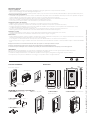
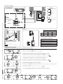
Posto esterno citofonico
Chiave a brugola
2 Tasselli e
2 viti con rosetta
Contenuto dell'imballo
ACCESSORI (da comandare separatamente)
Dimensioni
001DC00EGMA11 Pulsante singolo
001DC00EGMA12 Pulsante singolo e
altezza doppia
001DC00EGMA13 Pulsante doppio
LTP Tettuccio da parete 001DC00PLACO03 Scatola da incasso
001DC00PLACO02
Cornice da incasso
Alimentazione
Citofono

–
B
INT
M1 3/4
1/2
1
2
60
60
83.5
110
170
31
1
2
1
2
1
2
INT
1/2 3/4
INT
1/2 3/4
INT
1/2 3/4
INT
1/2 3/4
3
2
1
6
5
Pag. 3 - Manuale FA00955-IT - ver. 1 - 11/2017 - © CAME S.p.A. - I contenuti del manuale sono da ritenersi suscettibili di modifica in qualsiasi momento senza obbligo di preavviso.
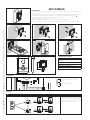
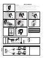
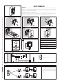
Installazione
Sganciare l’apparecchio dal supporto in plastica,facendolo scorrere su di esso dopo aver premuto il pulsante
plastico (figura 1).
Fissare il supporto in plastica alla scatola d’incasso tonda Ø 60 mm (figura 2) oppure alla scatola rettangolare
503 (figura 3) o alla parete (figura 4), utilizzando le viti in dotazione e rispettando l’indicazione UP .
La scatola deve essere installata a un'altezza adeguata per l'installatore.
Evitare il serraggio eccessivo delle viti.
Effettuati i collegamenti, agganciare il terminale al supporto plastico (figura 5-6).
Per sganciare l’apparecchio dal supporto plastico premere il gancio plastico e sollevare il terminale (figura 7).
Caratteristiche tecniche
Assorbimento: 80 mA max (<1 mA stand-by)
Assorbimento singolo LED (esclusione suone-
ria): 1 mA
Dimensioni: 110x170x31 mm
Temperatura di stoccaggio: -25°C +70 °C
Temperatura d'esercizio: 0 °C +35 °C
Grado di protezione IP: IP 20
Morsettiere
Selezioni
INT
Il jumper INT serve per creare due gruppi
intercom distinti: lasciare il jumper INT nella
posizione “1/2” sui derivati del primo gruppo
e spostare il jumper INT nella posizione “3/4”
sui derivati del secondo gruppo.
M1
BIngresso linea BUS (non polarizzato)
–Chiamata pianerottolo
001CS2BNC0

43,5
45
7,5 57
70
106
A
B
64,5
70
145
A
B
M2M1
+–
1
1
2
45
3
Pag. 4 - Manuale FA00955-IT - ver. 1 - 11/2 017 - © CAME S.p.A. - I contenuti del manuale sono da ritenersi suscettibili di modifica in qualsiasi momento senza obbligo di preavviso.
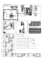
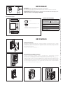
Caratteristiche tecniche
Alimentazione: 230 VAC 50÷60 Hz
Corrente assorbita: Imax
200 mA
AC
AC
Potenza dissipata: 10 W max
Alimentazione nominale: 18 VDC 1 A-0,5 A 1’/3’
Dimensioni: 4 DIN
Temperatura di stoccaggio: -25 °C + 70 °C
Temperatura d'esercizio: 0 °C +35 °C
Grado di protezione IP: IP 30
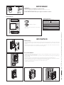
Installazione a parete
Con una chiave a brugola, svitare le viti di bloccaggio e togliere la placca (figura 1). Fissare i tasselli in dotazione
e avvitare il posto esterno (figura 2) all'altezza desiderata. Far passare la guaina con i conduttori d'impianto
come indicato in figura 2.
Estrarre il coprimorsetto in plastica ed effettuare i collegamenti (figura 3). Una volta terminati i collegamenti
reinserire i coprimorsetti. Montare la placca frontale (figura 1).
Installazione a incasso
Sigillare il contenitore da incasso all’altezza desiderata, facendo passare preventivamente la guaina con i con-
duttori dell’installazione attraverso uno dei punti di rottura (figura 4, punto A).
Nella messa in opera della scatola d’incasso si potranno evitare possibili deformazioni utilizzando l’apposito
distanziale in dotazione (figura 4 punto B).
Con una chiave a brugola, svitare le viti di bloccaggio e togliere la placca del posto esterno (figura 1).
Introdurre i cavi di collegamento nell'apposito foro (figura 2), fissare il posto esterno sulla cornice come indica-
to in figura 5; estrarre il coprimorsetto in plastica ed effettuare i collegamenti (figura 3).
Una volta terminati i collegamenti reinserire i coprimorsetti.
Montare la placca frontale (figura 1).
Installazione
L’alimentazione deve SEMPRE essere installata in verticale.
L’apparecchio è installabile su guida DIN (EN 50022) in un apposito quadro elettrico.
Per le dimensioni di ingombro vedere la fig. 1.
Prevedere una ventilazione sufficiente nel caso in cui l’alimentazione venga installata in un con-
tenitore.
Morsettiere
M1
~Rete
~
M2
–
+Alimentazione 18 VDC (*)
(*) L’apparecchiatura è protetta contro i sovrac-
carichi e i corto-circuiti.
001DC002AC
001CS2PLC0

M1
BOUT
M2
SW3
PROG
RESET
PROG
M2M1
+–
001DC005AC
B
B
NO
C
–+
NO
C
VAS/101
M1
BOUT
M2
SW3
PROG RESET
PROG
La
Lb
001DC002AC
c
f
d
g
b
h
a
X 5
beep
i
X 5
beep
e
Pag. 5 - Manuale FA00955-IT - ver. 1 - 11/2 017 - © CAME S.p.A. - I contenuti del manuale sono da ritenersi suscettibili di modifica in qualsiasi momento senza obbligo di preavviso.
Caratteristiche tecniche
Alimentazione: 16-18 VDC
Assorbimento: 120 mA (75 mA stand-by)
Dimensioni: 99x207x30 mm
Temperatura di stoccaggio: -25°C +70 °C
Temperatura d'esercizio: -15 °C +50 °C
Grado di protezione IP: IP 54
1- Ingresso in Programmazione.
Premere per 5 volte il pulsante entro 5 s a.
Un breve segnale acustico conferma l’ingresso in programmazione.
2- Programmazione della melodia associata alla chiamata dal posto esterno.
Per ascoltare in sequenza le melodie premere il tasto b.
Per selezionare la melodia ed uscire dalla programmazione premere il tasto c.
Per selezionare la melodia e proseguire con la programmazione premere il tasto d.
3- Programmazione della melodia associata alla chiamata dal pianerottolo.
Per ascoltare in sequenza le melodie premere il tasto e.
Per selezionare la melodia ed uscire dalla programmazione premere il tasto f.
Per selezionare la melodia e proseguire con la programmazione premere il tasto g.
4- Programmazione del numero di squilli di chiamata.
Premere il tasto h tante volte quanti sono gli squilli desiderati (da 1 a 6 squilli). Dopo 3 secondi dall’ultima
pressione del tasto verrà riprodotta la chiamata selezionata per il numero di squilli prescelto.
Per uscire dalla programmazione premere il tasto i.
☞ Per la programmazione della chiamata, vedere la documentazione dei posti esterni.
Configurazione melodie
☞ Bisogna eseguire, in successione, tutte le fasi di programmazione descritte di seguito:
Morsettiera
M1
BOUT Bus
(non polarizzato)
+Alimentazione
16-18 VDC
–
M2
–Massa
Pulsante
apriporta (NO)
Elettroserratura
12 V 1 A max
–
Funzioni delle morsettiere
Regolazioni Distanze
audio altoparlante
audio microfono
elettroserratura 1÷10 s. default 1 s)
Distanze
2x1 mm2UTP/CAT 5 2x2,5mm2
La ≤250 m ≤250 m –
Lb ≤25 m – ≤60 m
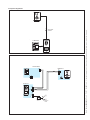
OPZIONE:
Modulo bus
2 uscite ausiliarie
Relè 1
Relè 2

2
INTERCOM 1/2 INTERCOM 3/4
2
001DC002AC
2
2
1
1 2
001DC002AC
2
+
–
M2
230 V
A
BIANCA-C
001DC002AC
M1
B
-
+
BOUT
-
-
-
M1
INT
1/2 3/4
PLACO-C
Automatisme
CAME
Relais
12Vcc
M2
250 m max.
2x1mm2
Pag. 6 - Manuale FA00955-IT - ver. 1 - 11/2 017 - © CAME S.p.A. - I contenuti del manuale sono da ritenersi suscettibili di modifica in qualsiasi momento senza obbligo di preavviso.
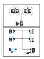
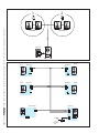
Esempi di collegamento

2.3
+
BOUT
-
M1
A
+
–
M2
-
-
M1
B
-
2.4
M1
B
-
1.1
M1
B
-
1.2
M1
B
-
INT
1/2 3/4
INT
1/2 3/4
INT
1/2 3/4
INT
1/2 3/4
Automatisme
CAME
Relais
12Vcc
M2
PLACO-C
BIANCA-C
BIANCA-C BIANCA-C
BIANCA-C
001DC002AC
2
INTERCOM 1/2 INTERCOM 3/4
2
001DC002AC
2
2
1
1 2
001DC002AC
2
Pag. 7 - Manuale FA00955-IT - ver. 1 - 11/2 017 - © CAME S.p.A. - I contenuti del manuale sono da ritenersi suscettibili di modifica in qualsiasi momento senza obbligo di preavviso.

CAME S.p.A.
Via Martiri Della Libertà, 15
31030 Dosson di Casier - Treviso - Italy
tel. (+39) 0422 4940 - fax. (+39) 0422 4941
Pag. 8 - Manuale FA00955-IT - ver. 1 - 11/2017 - © CAME S.p.A. - I contenuti del manuale sono da ritenersi suscettibili di modifica in qualsiasi momento senza obbligo di preavviso.

001CS2PLC0 001CS2BNC0
001DC002AC
M2M1
+–
AUDIO ENTRY KIT
001CK0001
INSTALLATION MANUAL
EN
English
FA00955-EN

135
99 30
3.5
6.5
243
207
135
99 30
3.5
6.5
243
207
Page 2 - Manual FA00955-EN - vers. 1 - 11/2017- © Came S.p.A. - The contents of this manual may be changed, at any time, and without notice.
General warnings
On opening the pack
• Read the instructions carefully before starting installation and proceed as specified by the manufacturer;
• After removing the packaging, check the condition of the unit;
• The packaging items (plastic bags, polystyrene foam etc.) must not be handled by children as they may be dangerous;
General installation instructions
• Installation, programming, commissioning and maintenance of the product must only be performed by qualified technicians who have been properly trained in
compliance with current standards, including health and safety regulations;
• Operate in sufficiently lit areas that are conducive to health and use tools, utensils and equipment that are in good working order;
• The device must be installed in accordance with the IP degree indicated in the technical features;
• If present, do not obstruct the openings or ventilation/heat dispersing holes;
Wiring the devices
• The electrical system must comply with current standards in the country of installation;
• Before connecting the units, check that the indications on the plate correspond with those of the mains;
• Protect units powered with mains voltage using a single pole mains switch with contact separation of at least 3 mm;
• Wires belonging to cables that are not used must be insulated.
• To prevent accidental contact, tighten the mains connection cables and those for the very low voltage signals separately.
• Weld the joints and the ends of the wires to prevent malfunctions caused by wire oxidation;
Installation completed
• When installation is completed, always check for correct operation of the unit and the system as a whole;
• The installer must check that the information required by the user is present and handed over;
Maintenance
• Before performing any cleaning or maintenance operation, disconnect the power supply to the device. If the units are mains-powered, disconnect the power using
the switch upstream from the units;
• In the case of device failure or malfunction, disconnect it from the power supply and do not tamper with it;
• Should the unit be in need of repair, contact only a technical support centre authorised by the manufacturer and always use spare parts provided by CAME S.p.A.
The units must only be used for the purpose for which they were explicitly designed.
Failure to follow the instructions provided above may compromise the unit’s safety.
The manufacturer declines all liability for any damage as a result of improper, incorrect or unreasonable use.
DISPOSAL
Do not litter the environment with packing material: make sure it is disposed of according to the regulations in force in the country where the product is used.
When the equipment reaches the end of its life cycle, take measures to ensure it is not discarded in the environment.
The equipment must be disposed of in compliance with the regulations in force, recycling its component parts wherever possible.
Components that qualify as recyclable waste feature the relevant symbol and the material’s abbreviation.
Audio entry control
Allen wrench
2 plugs and
2 screws with washer
Packaging contents
ACCESSORIES (to be purchased separately)
Dimensions
001DC00EGMA11 Single button
001DC00EGMA12 Single button and
double height
001DC00EGMA13 Double button
LTP Wall roof 001DC00PLACO03 Recessed box
001DC00PLACO02 Recessed frame
Power supplier
Entry phone

–
B
INT
M1 3/4
1/2
1
2
60
60
83.5
110
170
31
1
2
1
2
1
2
INT
1/2 3/4
INT
1/2 3/4
INT
1/2 3/4
INT
1/2 3/4
3
2
1
6
5
Page 3 - Manual FA00955-EN - vers. 1 - 11/2017- © Came S.p.A. - The contents of this manual may be changed, at any time, and without notice.
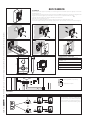
Installation
Remove the unit from the plastic support by sliding it after pressing the plastic button (figure 1).
Fasten the plastic support to the round built-in box of Ø 60 mm (figure 2) or to the rectangular box 503 (figure
3) or to the wall (figure 4), using the provided screws and observing the UP indication .
The box must be fitted at a suitable height in relation to the installer.
Avoid excessive tightening of the screws.
Once the connections have been made, attach the terminal to the plastic support (figure 5-6).
To release the unit from the plastic support, press the plastic hook and lift the terminal (figure 7).
Technical features
Absorption: 80 mA max (<1 mA stand-by)
Single LED absorption (ring disabled): 1 mA
Dimensions: 110x170x31 mm
Storage temperature: -25 °C +70 °C
Operating temperature: 0 °C +35 °C
IP degree: IP 20
Terminal boards
Selections
INT
The INT jumper is used to create two sepa-
rate intercom groups: leave the INT jumper
in position “1/2” on the receivers of the first
group and move the INT jumper to position
“3/4” on the receivers of the second group.
M1
BBUS line input (not polarised)
–Doorbell
001CS2BNC0

43,5
45
7,5 57
70
106
A
B
64,5
70
145
A
B
M2M1
+–
1
1
2
45
3
Page 4 - Manual FA00955-EN - vers. 1 - 11/2017- © Came S.p.A. - The contents of this manual may be changed, at any time, and without notice.
Technical features
Power supply: 230 VAC 50-60 Hz
Current absorbed Imax
200 mA
AC
AC
Power dissipated: 10 W max
Rated power supply: 18 VDC 1 A-0.5 A 1’/3’
Dimensions: 4 DIN
Storage temperature: -25 °C + 70 °C
Operating temperature: 0 °C +35 °C
IP degree: IP 30
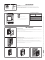
Wall mounting
With the Allen wrench, unscrew the blocking screws and remove the plate (figure 1). Fix the given plugs and
screw the entry panel (figure 2) at the desired height. Run the sheath with the system conductors as shown
in figure 2.
Extract the plastic terminal cover and wire the connections (figure 3). Once all the connections have been
made, re-insert the terminal covers. Install the front plate (figure 1).
Recessed installation
Install the recessed box at the desired, but in advance, run the sheath with the system conductors through one
of the breaking points (figure 4 point A).
During installation of the recessed box it is possible to avoid any deformation by using the provided spacer
(figure 4 point B).
With the Allen wrench, unscrew the blocking screws and remove the entry panel plate (figure 1).
Introduce the cable connections in the special hole (figure 2) and fix the entry panel on the frame as shown in
figure 5; extract the plastic terminal cover and wire the connections (figure 3).
Once all the connections have been made, re-insert the terminal covers.
Install the front plate (figure 1).
Installation
The power supplier must ALWAYS be installed vertically.
The unit can be installed on a DIN guide (EN 50022) in a special electrical panel.
For the overall dimensions, see fig. 1.
Provide sufficient ventilation if the power supplier is installed in a container.
Terminal boards
M1
~Mains
~
M2
–
+18 VDC power supply (*)
(*) The unit is protected against overloads and
short circuits.
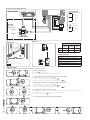
001DC002AC
001CS2PLC0

M1
BOUT
M2
SW3
PROG
RESET
PROG
M2M1
+–
001DC005AC
B
B
NO
C
–+
NO
C
VAS/101
M1
BOUT
M2
SW3
PROG RESET
PROG
La
Lb
001DC002AC
c
f
d
g
b
h
a
X 5
beep
i
X 5
beep
e
Page 5 - Manual FA00955-EN - vers. 1 - 11/2017- © Came S.p.A. - The contents of this manual may be changed, at any time, and without notice.
Technical features
Power supply: 16-18 VDC
Absorption: 120 mA max (75 mA stand-by)
Dimensions: 99x207x30 mm
Storage temperature: -25 °C +70 °C
Operating temperature: -15 °C +50 °C
IP degree: IP 54
1- Going into Programming.
Press button 5 times in 5 secs a.
A short beep confirms that you have entered programming mode.
2- Programming the melody associated with a call from the entry panel.
To listen to the melodies in sequence, press key b.
To select the melody and exit programming, press key c.
To select the melody and continue with programming, press key d.
3- Programming the melody associated with a call from the front door.
To listen to the melodies in sequence, press key e.
To select the melody and exit programming, press key f.
To select the melody and continue with programming, press key g.
4- Programming the number of rings for the call.
Press key h as many times as you want it to ring (from 1 to 6 rings). Three seconds after the last press of the
key the call selected for the chosen number of rings will be played back.
To exit programming, press key i.
☞ See the entry panel documentation for call programming.
Setting melodies
☞ All the programming stages described below must be carried out in sequence:
Terminal board
M1
BOUT Bus
(not polarised)
+Power supply
16-18 VDC
–
M2
–Earth
Door release
button (NO)
Electric lock
12 V 1 A max
–
Functions of the terminal boards
Adjustments Distances
speak audio
microphone audio
electric lock 1-10 s. default 1 s)
Distances
2x1 mm2UTP/CAT 5 2x2.5
mm2
La ≤250 m ≤250 m –
Lb ≤25 m – ≤60 m
OPTIONAL:
Bus module
2 auxiliary exits
Relay 1
Relay 2

2
INTERCOM 1/2 INTERCOM 3/4
2
001DC002AC
2
2
1
1 2
001DC002AC
2
+
–
M2
230 V
A
BIANCA-C
001DC002AC
M1
B
-
+
BOUT
-
-
-
M1
INT
1/2 3/4
PLACO-C
Automatisme
CAME
Relais
12Vcc
M2
250 m max.
2x1mm2
Page 6 - Manual FA00955-EN - vers. 1 - 11/2017- © Came S.p.A. - The contents of this manual may be changed, at any time, and without notice.
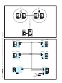
Connection examples

2.3
+
BOUT
-
M1
A
+
–
M2
-
-
M1
B
-
2.4
M1
B
-
1.1
M1
B
-
1.2
M1
B
-
INT
1/2 3/4
INT
1/2 3/4
INT
1/2 3/4
INT
1/2 3/4
Automatisme
CAME
Relais
12Vcc
M2
PLACO-C
BIANCA-C
BIANCA-C BIANCA-C
BIANCA-C
001DC002AC
2
INTERCOM 1/2 INTERCOM 3/4
2
001DC002AC
2
2
1
1 2
001DC002AC
2
Page 7 - Manual FA00955-EN - vers. 1 - 11/2017- © Came S.p.A. - The contents of this manual may be changed, at any time, and without notice.

CAME S.p.A.
Via Martiri Della Libertà, 15
31030 Dosson di Casier - Treviso - Italy
tel. (+39) 0422 4940 - fax. (+39) 0422 4941
Page 8 - Manual FA00955-EN - vers. 1 - 11/2017- © Came S.p.A. - The contents of this manual may be changed, at any time, and without notice.

001CS2PLC0 001CS2BNC0
001DC002AC
M2M1
+–
001CK0001
MANUEL D’INSTALLATION
FR
Français
FA00955-FR
VIDEO KIT

135
99 30
3.5
6.5
243
207
135
99 30
3.5
6.5
243
207
Page 2 - Manuel FA00955-FR - vers. 1 - 11/2017- © Came S.p.A. - Le contenu de ce manuel est susceptible de subir des modifications à tout moment et sans aucun préavis.
Avertissements généraux
Au moment de l’ouverture de l’emballage
• Lire attentivement les instructions avant de commencer l’installation et effectuer les opérations comme spécifié par le est bien en bon état ;
• Après l’avoir déballé, vérifier que l’appareil est bien en bon état ;
• Ne pas laisser les éléments d’emballage (sachets en plastique, polystyrène expansé, etc.) à la portée des enfants car ils constituent une source potentielle de danger ;
Prescriptions générales pour l’installation
• L’installation, la programmation, la mise en service et l’entretien du produit ne doivent être effectués que par du personnel technique qualifié et spécialisé, en respec-
tant les normes en vigueur, y compris celles en matière de prévention des accidents ;
• Travailler dans des lieux salubres et suffisamment éclairés et n’utiliser que des outils et des instruments en bon état ;
• Le dispositif doit être installé conformément au degré IP indiqué dans les caractéristiques techniques ;
• Ne pas obstruer les éventuelles ouvertures/orifices de ventilation ou d’élimination de la chaleur;
Branchement électrique des dispositifs
• L’installation électrique devra être réalisée conformément aux normes en vigueur dans le pays d’installation ;
• Avant de raccorder les appareils, contrôler que les indications reportées sur la plaque correspondent à celles du réseau électrique ;
• Protéger les appareils sous tension de réseau par le biais d’un interrupteur de réseau omnipolaire avec séparation des contacts d’au moins 3 mm ;
• Les conducteurs non utilisés doivent être isolés ;
• Pour éviter les contacts accidentels, serrer séparément les câbles de branchement au réseau et ceux des signaux en très basse tension ;
• Souder les jonctions et la partie terminale des fils afin d’éviter que leur oxydation ne crée des dysfonctionnements ;
Fin de l’installation
• À la fin de l’installation, toujours contrôler le bon fonctionnement de l’appareil et de toute l’installation ;
• L’installateur doit s’assurer que les informations utiles à l’utilisateur sont bien présentes et qu’elles lui ont bien été fournies ;
Entretien
• Avant d’effectuer toute opération de nettoyage ou d’entretien, couper l’alimentation électrique du dispositif ; en cas d’appareils sous tension de réseau, couper l’ali-
mentation en ouvrant l’interrupteur situé en amont de ces derniers ;
• En cas de panne et/ou de mauvais fonctionnement d’un dispositif, le débrancher du réseau électrique, sans tenter aucune réparation ;
• Pour toute réparation, adressez-vous uniquement à un centre d’assistance technique agréé par le fabricant et dans tous les cas utilisez toujours des pièces de rechan-
ge fournies par CAME s.p.a ;
Les appareils devront être destinés uniquement à l’usage pour lequel ils ont expressément été conçus ;
Le non-respect des prescriptions susmentionnées pourrait compromettre la sécurité de l’appareil ;
Le fabricant ne pourra dans tous les cas être tenu responsable des dommages dérivant d’une utilisation incorrecte ou erronée.
ÉLIMINATION
S’assurer que le matériel d’emballage n’est pas abandonné dans la nature et qu’il est éliminé conformément aux normes en vigueur dans le pays d’utilisation du produit.
À la fin du cycle de vie de l’appareil, faire en sorte qu’il ne soit pas abandonné dans la nature.
L’appareil doit être éliminé conformément aux normes en vigueur et en privilégiant le recyclage de ses pièces.
Le symbole et le sigle du matériau sont indiqués sur les pièces pour lesquelles le recyclage est prévu.
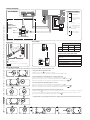
Poste extérieur d’interphonie
Clé à six pans
2 Chevilles et
2 vis avec rondelle
Contenu de l’emballage
ACCESSOIRES (à commander séparément)
Dimensions
001DC00EGMA11 Bouton simple
001DC00EGMA12 Bouton simple et
hauteur double
001DC00EGMA13 Bouton double
LTP Visière de protection murale 001DC00PLACO03 Boîtier à encastrer
001DC00PLACO02 Cadre pour
encastrement
Alimentation
Combiné

–
B
INT
M1 3/4
1/2
1
2
60
60
83.5
110
170
31
1
2
1
2
1
2
INT
1/2 3/4
INT
1/2 3/4
INT
1/2 3/4
INT
1/2 3/4
3
2
1
6
5
Page 3 - Manuel FA00955-FR - vers. 1 - 11/2017- © Came S.p.A. - Le contenu de ce manuel est susceptible de subir des modifications à tout moment et sans aucun préavis.
Installation
Retirer l’appareil du support en plastique, en le faisant glisser sur lui-même après avoir appuyé sur la touche
plastique (figure 1).
Fixer le support en plastique au boîtier d’encastrement rond Ø 60 mm (figure 2) ou au boîtier rectangulaire 503
(figure 3) ou sur le mur (figure 4), en utilisant les vis fournies et en respectant l’indication UP .
Le boîtier doit être installé à une hauteur adéquate pour l’utilisateur.
Éviter de serrer excessivement les vis.
Une fois les raccordements effectués, fixer le terminal au support en plastique (figures 5-6).
Pour retirer l’appareil du support en plastique, appuyer sur le clip en plastique et soulever le terminal (figure 7).
Caractéristiques techniques
Absorption : 80 mA max (<1 mA stand-by)
Absorption individuelle LED (Désactivation
sonnerie) : 1 mA
Dimensions : 110x170x31 mm
Température de stockage : -25°C +70 °C
Température de fonctionnement : 0 °C +35 °C
Degré IP : IP 20
Borniers
Sélections
INT
Le cavalier INT sert à créer deux groupes in-
tercom distincts : laisser le cavalier INT sur
la position “1/2” sur les dérivés du premier
groupe et déplacer le cavalier INT sur la posi-
tion “3/4” sur les dérivés du deuxième groupe.
M1
BEntrée ligne BUS (non polarisé)
–Appel depuis le palier
001CS2BNC0

43,5
45
7,5 57
70
106
A
B
64,5
70
145
A
B
M2M1
+–
1
1
2
45
3
Page 4 - Manuel FA00955-FR - vers. 1 - 11/2017- © Came S.p.A. - Le contenu de ce manuel est susceptible de subir des modifications à tout moment et sans aucun préavis.
Caractéristiques techniques
Alimentation : 230 VAC 50÷60 Hz
Courant absorbé: Imax
=200 mA
AC
AC
Puissance dissipée : 10 W max
Alimentation nominale : 18 VDC 1 A-0,5 A 1’/3’
Dimensions : 4 DIN
Température de stockage : -25 °C + 70 °C
Température de fonctionnement : 0 °C +35 °C
Degré IP : IP 30
Installation murale
À l’aide de la clé à six pans, dévisser les vis de blocage et retirer la plaque (figure 1). Fixer les chevilles fournies
et visser le poste extérieur (figure 2) à la hauteur souhaitée. Faire passer la gaine avec les conducteurs de l’ins-
tallation comme indiqué à la figure 2.
Extraire le cache-borne en plastique et effectuer les branchements (figure 3). Une fois les branchement termi-
nés, réinsérer les cache-bornes. Monter la plaque frontale (figure 1).
Installation à encastrer
Sceller le boîtier à encastrer à la hauteur souhaitée en faisant préalablement passer la gaine avec les conduc-
teurs de l’installation à travers un des points de rupture (figure 4 point A).
Lors de la mise en place du boîtier à encastrer, éviter toute déformation en utilisant la cale fournie et prévue à
cet effet (figure 4 point B).
À l’aide de la clé à six pans, dévisser les vis de blocage et retirer la plaque du poste extérieur (figure 1).
Introduire les câbles de branchement dans le trou prévu à cet effet (figure 2), fixer le poste extérieur sur le ca-
dre comme indiqué à la figure 5 ; extraire le cache-borne en plastique et effectuer les branchements (figure 3).
Une fois les branchements terminés, réinsérer les cache-bornes.
Monter la plaque frontale (figure 1).
Installation
Le bloc d’alimentation doit TOUJOURS être installé à la verticale.
L’appareil peut être installé sur rail DIN (EN 50022) dans un tableau électrique prévu à cet effet.
Pour les dimensions hors tout, voir la fig. 1.
Prévoir une ventilation suffisante en cas de bloc d’alimentation installé dans un boîtier.
Borniers
M1
~Secteur
~
M2
–
+Alimentation 18 VDC (*)
(*) L’appareil est protégé électroniquement con-
tre les surcharges et les courts-circuits.
001DC002AC
001CS2PLC0
La pagina si sta caricando...
La pagina si sta caricando...
La pagina si sta caricando...
La pagina si sta caricando...
La pagina si sta caricando...
La pagina si sta caricando...
La pagina si sta caricando...
La pagina si sta caricando...
La pagina si sta caricando...
La pagina si sta caricando...
La pagina si sta caricando...
La pagina si sta caricando...
-
 1
1
-
 2
2
-
 3
3
-
 4
4
-
 5
5
-
 6
6
-
 7
7
-
 8
8
-
 9
9
-
 10
10
-
 11
11
-
 12
12
-
 13
13
-
 14
14
-
 15
15
-
 16
16
-
 17
17
-
 18
18
-
 19
19
-
 20
20
-
 21
21
-
 22
22
-
 23
23
-
 24
24
-
 25
25
-
 26
26
-
 27
27
-
 28
28
-
 29
29
-
 30
30
-
 31
31
-
 32
32


in altre lingue
- français: CAME PERLA, PLACO Guide d'installation
Documenti correlati
-
CAME PERLA, PLACO Guida d'installazione
-
-
-
-
-
-
-
-
-