Gigabyte GA-K8NNXP-940 Manuale del proprietario
- Tipo
- Manuale del proprietario

GA-K8NNXP-940
User's Manual
AMD Socket 940 Processor Motherboard
Rev. 1001
12ME-K8NN940-1001
Copyright
© 2003 GIGABYTE TECHNOLOGY CO., LTD
Copyright by GIGA-BYTE TECHNOLOGY CO., LTD. ("GBT"). No part of this manual may be reproduced or transmitted in any from
without the expressed, written permission of GBT.
Trademarks
Third-party brands and names are the property of their respective owners.
Notice
Please do not remove any labels on motherboard, this may void the warranty of this motherboard.
Due to rapid change in technology, some of the specifications might be out of date before publication of this booklet.
The author assumes no responsibility for any errors or omissions that may appear in this document nor does the author make a
commitment to update the information ontained herein.
k8nnxp-940_1001_i.p65 2003/10/2, ¤U¤È 05:181

Mother Board
GA-K8NNXP-940
October 13,2003
k8nnxp-940_1001_i.p65 2003/10/2, ¤U¤È 05:182

Motherboard
GA-K8NNXP-940
October 13 ,2003
k8nnxp-940_1001_i.p65 2003/10/2, ¤U¤È 05:183

- 4 -GA-K8NNXP-940 Motherboard
English
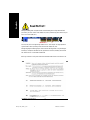
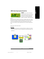
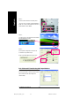
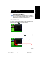
When you installing AGP card, please make sure the following notice is fully understood and
practiced. If your AGP card has "AGP 4X/8X(1.5V) notch" (show below), please make sure your
AGP card is AGP 4X/8X(1.5V).
AGP 2X(3.3V) card is not supported by nVIDIA® nForce™ 3 150 chipset. You might experience
system unable to boot up normally. Please insert an AGP 4X/8X(1.5V) card.
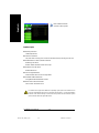
Although Gigabyte's AG32S(G) graphics card is based on ATi Rage 128 Pro chip, the design of
AG32S(G) is compliance with AGP 4X(1.5V) specification. Therefore, AG32S(G) will work fine
with nVIDIA® nForce™ 3 150 based motherboards.
Before you install PCI cards, please remove the Dual BIOS label from PCI slots if there is one.
Read Me First !
AGP 4X/8X notch
k8nnxp-940_1001_i.p65 2003/10/2, ¤U¤È 05:184

5 Read Me First
English
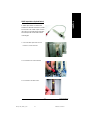
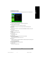
Installing the motherboard to the chassis…
If the motherboard has mounting holes, but they don't line up with the holes on the base and there
are no slots to attach the spacers, do not become alarmed you can still attach the spacers to the
mounting holes. Just cut the bottom portion of the spacers (the spacer may be a little hard to cut off,
so be careful of your hands). In this way you can still attach the motherboard to the base without
worrying about short circuits. Sometimes you may need to use the plastic springs to isolate the
screw from the motherboard PCB surface, because the circuit wire may be near by the hole. Be
careful, don't let the screw contact any printed circuit write or parts on the PCB that are near the
fixing hole, otherwise it may damage the board or cause board malfunctioning.
Preparing Your Computer
Computer motherboards and expansion cards contain very delicate Integrated Circuit (IC) chips. To
protect them against damage from static electricity, you should follow some precautions whenever
you work on your computer.
1. Unplug your computer when working on the inside.
2. Use a grounded wrist strap before handling computer components. If you do not have
one, touch both of your hands to a safely grounded object or to a metal object, such as
the power supply case.
3. Hold components by the edges and try not touch the IC chips, leads or connectors, or
other components.
4. Place components on a grounded antistatic pad or on the bag that came with the
components whenever the components are separated from the system.
5. Ensure that the ATX power supply is switched off before you plug in or remove the ATX
power connector on the motherboard.
The manufacturer assumes no liability for any damage, caused directly or indirectly, by improper
installation of any comfortable performing the installation, consult a qualified computer technician.
Damage to system components, and injury to yourself may result if power is applied during
installation.
k8nnxp-940_1001_i.p65 2003/10/2, ¤U¤È 05:185

- 6 -GA-K8NNXP-940 Motherboard
English
Table of Content
Read Me First !.......................................................................................4
Chapter 1 Introduction............................................................................8
1-1 Check List ....................................................................................8
1-2 Features Summary................................................................................ 8
1-3 GA-K8NNXP-940 Motherboard Layout............................................... 11
1-4 Block Diagram - GA-K8NNXP-940.....................................................12
Chapter 2 Hardware Installation Process.............................................15
Step 1: Installing Processor and CPU Cooling Fan..................................16
Step 2: Installing Memory Modules...........................................................18
Step 3: Installing expansion cards ............................................................21
Step 3-1: AGP Card Installation.....................................................................................21
Step 3-2: K8DPS (Dual Power System) Installation....................................................22
Step 4: Connect ribbon cables, cabinet wires and power supply ............23
Step 4-1: I/O Back Panel Introduction...........................................................................23
Step 4-2: Connectors Introduction.................................................................................25
Chapter 3 BIOS Setup .........................................................................41
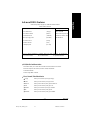
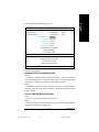
The Main Menu (For example: BIOS Ver. : E08)...................................... 42
Standard CMOS Features......................................................................... 44
Advanced BIOS Features ..........................................................................47
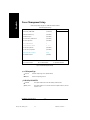
Integrated Peripherals ..............................................................................49
Power Management Setup .......................................................................54
PnP/PCI Configurations.............................................................................57
k8nnxp-940_1001_i.p65 2003/10/2, ¤U¤È 05:186

Table of Content
English
- 7 -
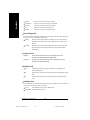
PC Health Status........................................................................................58
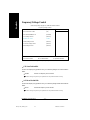
Frequency/Voltage Control........................................................................60
Load Fail-Safe Defaults............................................................................. 62
Load Optimized Defaults...........................................................................63
Set Supervisor/User Password.................................................................. 64
Save & Exit Setup.......................................................................................65
Exit Without Saving ...................................................................................66
Chapter 4 Technical Reference ...........................................................69
@BIOS™ Introduction.................................................................................69
EasyTune™ 4 Introduction .........................................................................70
K8DPS (Dual Power System) Introduction................................................71
Flash BIOS Method Introduction...............................................................72
2- / 4- / 6-Channel Audio Function Introduction ........................................ 82
Jack-Sensing Introduction......................................................................... 88
UAJ Introduction ........................................................................................90
Xpress Recovery Introduction ...................................................................92
Chapter 5 Appendix.............................................................................97
k8nnxp-940_1001_i.p65 2003/10/2, ¤U¤È 05:187

- 8 -GA-K8NNXP-940 Motherboard
English
1-1 Item Checklist
The GA-K8NNXP-940 motherboard
CD for motherboard driver & utility
GA-K8NNXP-940 user's manual
Quick PC Installation Guide
GigaRAID manual
SATA RAID manual
GC-SATA card (Optional)
(Manual; SATA cable x 1; Power cable x 1)
IDE cable x 3 / Floppy cable x 1
Serial ATA cable x 1
Serial ATA power cable x 1
USB & IEEE 1394 cable x 1
USB cable x1
Audio Combo Kit x 1
(SURROUND-Kit + SPDIF Out Kit)
I/O Shield
K8DPS x 1
Motherboard Settings Label
Chapter 1 Introduction
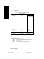
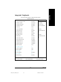
Form Factor 30.5cm x 24.4cm ATX size form factor, 6 layers PCB
CPU Socket 940 for AMD AlthlonTM 64 FX / Opteron processor (K8)
128K L1& 1-Mbyte 16-Way Associative ECC-Protected L2 Cache
Chipset nVIDIA® nForce™ 3 150
Memory 4 184-pin DDR DIMM sockets
Supports Dual Channel DDR400/DDR333/DDR266/DDR200 DIMM
Only supports Registered DIMMs with a 64-bit /128-bit data bus
with 8-bit /16-bits of Error Correcting Code (ECC)
Supports 128MB/256MB/512MB/1GB/2GB DRAM
Supports up to 8GB DRAM (Max)
I/O Control IT8712F
Slots 1 AGP slot supports 8X/4X mode,
AGP3.0 8X interface at 533MT/S
5 PCI slots support 33MHz & PCI 2.3 compliant
1-2 Features Summary
to be continued......
k8nnxp-940_1001_i.p65 2003/10/2, ¤U¤È 05:188

Introduction
English
- 9 -
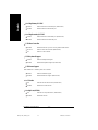
On-Board IDE 2 IDE controllers provides IDE HDD/CD-ROM (IDE1, IDE2) with
PIO, Bus Master (Ultra DMA33/ATA66/ATA100/ATA133) operation
modes
IDE3 and IDE4 compatible with RAID, Ultra ATA133/100, IDE
Built-in GigaRAID IT8212F
Hardware Monitor CPU/System/Power fan revolution detect
CPU temperature detect
CPU warning temperature
System voltage detect
CPU/System/Power fan fail warning
CPU Smart Fan control
Thermal shutdown function
On-Board Peripherals 1 Floppy port supports 2 FDD with 360K, 720K,1.2M, 1.44M
and 2.88M bytes
1 Parallel port supports Normal/EPP/ECP mode
2 Serial ports (COMA & COMB)
6 USB 2.0/1.1 ports (4 x Front by cable)
3 IEEE1394 ports (by cable),IEEE1394b can approach the
maximum speed to 800Mb/S, but the speed can be achieved only
when you use particular IEEE1394b cable.
1 IrDA connector for IR
1 Front Audio connector
On-Board LAN Dual LAN (Gigabit Ethernet RTL8110S)+(10/100 Ethernet RTL8201)
2 RJ45 ports
On-Board Sound Realtek ALC658 CODEC (UAJ)
Supports Jack Sensing function
Line Out / 2 front speaker
Line In / 2 rear speaker (by s/w switch)
Mic In / center & subwoofer (by s/w switch)
SPDIF In / Out
CD In / AUX In / Game port
On-Board SATA RAID Onboard Silicon Image SiI3512
Supports Disk striping (RAID0) or DISK Mirroring (RAID1)
Supports UDMA up to 150 MB/sec
Up to 2 SATA Device
Supports hot plug function
to be continued......
k8nnxp-940_1001_i.p65 2003/10/2, ¤U¤È 05:189

- 10 -GA-K8NNXP-940 Motherboard
English
On-Board IDE RAID Onboard GigaRAID IT8212F chipset
Supports data striping (RAID 0) or mirroring (RAID 1) or
striping+mirroring (RAID 0 + RAID 1)
Supports JBOD function
Supports concurrent dual ATA133 IDE controller operation
Support ATAPI mode for HDD
Supports IDE bus master operation
Support ATA133/RAID mode switch by BIOS
Displays status and error checking messages during boot-up
Mirroring supports automatic background rebuilds
Features LBA and Extended Interrupt 13 drive translation in
controller onboard BIOS
On-Board IEEE1394 Built-in Ti TSB82AA2
PS/2 Connector PS/2 Keyboard interface and PS/2 Mouse interface
BIOS Licensed AWARD BIOS
Supports Dual BIOS
Supports Face Wizard
Supports Q-Flash
Additional Features Supports CPU Dual Power System (DPS)
PS/2 Keyboard power on
PS/2 Mouse power on
External Modem ring on
STR(Suspend-To-RAM)
Wake on LAN (WOL)
AC Recovery
Poly fuse for keyboard over-current protection
USB KB/Mouse wake up from S3
Supports Easy Tune 4
Supports @BIOS
Overclocking Over Voltage (CPU/DDR/AGP) by BIOS
Over Clock (CPU/DDR/AGP) by BIOS
Please set the CPU host frequency in accordance with your processor's specifications.
We don't recommend you to set the system bus frequency over the CPU's specification because
these specific bus frequencies are not the standard specifications for CPU, chipset and most of the
peripherals. Whether your system can run under these specific bus frequencies properly will
depend on your hardware configurations, including CPU, Chipsets, SDRAM, Cards…etc.
k8nnxp-940_1001_i.p65 2003/10/2, ¤U¤È 05:1810

Introduction
English
- 11 -
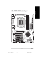
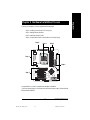
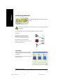
nVIDIA®
nForce™ 3
150
CD_IN
GA-K8NNXP-940
KB_MS
COMB
LPT
USB
LAN1
(Gigabit
Ethernet)
ATX_12V
SOCKET 940
CPU_FAN
IDE1
IDE2
DDR2
COMA
PWR_LED
BAT
PCI1
PCI2
PCI3
F_USB1
IT8712F
MAIN
BIOS
CODEC
PWR_FAN
DDR3
PCI4
PCI5
GAME
F_AUDIO
AUX_IN
IR
IDE3
GigaRAID
IT8212
BACKUP
BIOS
SiI3512
SATA1_SII
RAM_LED
ATX
SYS_FAN
VRM_CONN
NB_FAN
IDE4
DDR1
SPDIF_IO
SUR_CEN
2X_DET
AUDIO
F_PANEL
1-3 GA-K8NNXP-940 Motherboard Layout
F1_1394
INFO_LINK
AGP
LAN2
(10/100)
FDD
SATA0_SII
RTL8201
TSB82AA2
F2_1394
RTL8110S
TSB81BA3
F_USB2
CLR_CMOS
DDR4
k8nnxp-940_1001_i.p65 2003/10/2, ¤U¤È 05:1811

- 12 -GA-K8NNXP-940 Motherboard
English
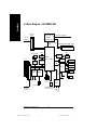
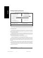
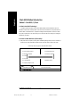
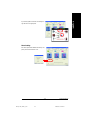
1-4 Block Diagram - GA-K8NNXP-940
CPUCLK+/- (200MHz)
HyperTransport
Bus
AGP Slot
4X/8X
AGPCLK
(66MHz)
5 PCI
PCICLK
(33MHz)
RJ45
RTL8110S
AMD
AlthlonTM 64 FX
/Opteron
processor (K8)
IDE3
SiI3512
2 Serial ATA
IDE4
GigaRAID
IT8212
DDR400/DDR333/266/200 DIMM
Registered DIMMs
nVIDIA
nForce™ 3 150
LPC BUS
6 USB
Ports
ATA33/66/100/133
IDE Channels
IT8712
24 MHz
33 MHz
Game Port
Floppy
LPT Port
PS/2 KB/Mouse
2 COM Ports
BIOS IR
LAN1
RTL8201 RJ45
LAN2
Ti1394b
AC97 Link
MIC
LINE-IN
LINE-OUT
AC97
CODEC
3 IEEE1394
k8nnxp-940_1001_i.p65 2003/10/2, ¤U¤È 05:1812

Introduction
English
- 13 -
k8nnxp-940_1001_i.p65 2003/10/2, ¤U¤È 05:1813

- 14 -GA-K8NNXP-940 Motherboard
English
k8nnxp-940_1001_i.p65 2003/10/2, ¤U¤È 05:1814

Hardware Installation Process
English
- 15 -
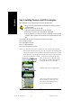
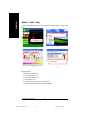
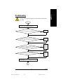
To set up your computer, you must complete the following steps:
Step 1- Installing Processor and CPU Cooling Fan
Step 2- Installing Memory Modules
Step 3- Installing Expansion Cards
Step 4- Connect ribbon Cables, Cabinet Wires, And Power Supply
Chapter 2 Hardware Installation Process
Step 2
Step 4
Step 3
Step 4
Step 1
Step 4
Congratulations! You have accomplished the hardware installation!
Turn on the power supply or connect the power cable to the power outlet. Continue with the
BIOS/software installation.
k8nnxp-940_1001_q.p65 2003/10/2, ¤U¤È 05:1815

- 16 -GA-K8NNXP-940 Motherboard
English
Socket
Actuation Lever
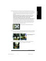
Step 1: Installing Processor and CPU Cooling Fan
The installation of the processor and cooling fan is performed in four main steps:
Step 1-1. Processor insertion
Step 1-2. Applying thermal grease
Step 1-3. Cooling fan attachment
Step 1-4. Connecting processor fan power
Before installing the processor and cooling fan, adhere to the following warning:
1. The processor will overheat without the heatsink and/or fan, resulting in permanent
irreparable damage.
2. Never force the processor into the socket.
3. Apply thermal grease between the processor and cooling fan.
4. Please make sure the CPU type is supported by the motherboard.
5. If you do not match the CPU socket Pin 1 and CPU cut edge well, it will cause improper
installation. Please change the insert orientation. Please use AMD approved cooling
fan.
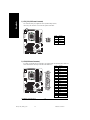
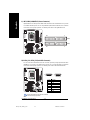
Step1-1. First, check the processor pins to see that none are bent. Move the socket lever to the
unlocked position as shown in Figure 1 & Figure 2.(90o to the plane of the motherboard) prior
to inserting the processor. The A1 pin location is designated on the processor by a copper
triangle that matches up to a triangle on the socket as shown in Figure 3. Align the processor
to the socket and gently lower it into place. Do not force the processor into the socket.
Figure 1.Angling the rod to 65-degree maybe
feel a kind of tight , and then continue pull the rod
to 90-degree when a noise “cough” made.
Figure 2.Pull the rod to the 90-degree directly.
Angling the
rod to 650
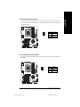
Figure 3. A1 pin location on the Socket and
Processor.Move the socket lever to the
locked position while holding pressure on
the center of the processor.
k8nnxp-940_1001_q.p65 2003/10/2, ¤U¤È 05:1816

Hardware Installation Process
English
- 17 -
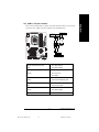
Step1-2. When the processor is installed in the socket, apply thermal grease to the processor(as
shown in Figure 4) prior to installing the heatsink. AMD recommends using a high thermal
conductivity grease for the thermal interface material rather than a phase change material.
Phase change materials develop strong adhesive forces between the heatsink and
processor.
Removing the heatsink under such conditions can cause the processor to be
removed from the socket without moving the socket lever to the unlocked
position and then damage the processor pins or socket contacts.
** We recommend you to apply the thermal tape to provide better heat conduction between your
CPU and heatsink. (The CPU cooling fan might stick to the CPU due to the hardening of the
thermal paste. During this condition if you try to remove the cooling fan, you might pull the
processor out of the CPU socket alone with the cooling fan, and might damage the processor.
To avoid this from happening, we suggest you to either use thermal tape instead of thermal
paste, or remove the cooling fan with extreme caution.)
Figure 4. Application of Thermal Grease to the processor.
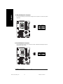
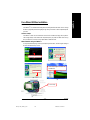
Step 1-4. Connect the fan power wires to the header on the motherboard as shown in Figure 7.
Figure 7. Connecting the Fan Power Wires
Step 1-3.Once the thermal grease has been applied to the processor, the heatsink can be attached to
the processor. Align the heatsink assembly with the support frame mating with the backer
plate standoffs as shown in Figure 5&6.
Figure 5&6 Alignment of Heatsink
Assembly with Standoffs
k8nnxp-940_1001_q.p65 2003/10/2, ¤U¤È 05:1917

- 18 -GA-K8NNXP-940 Motherboard
English
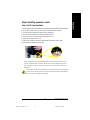
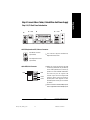
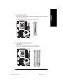
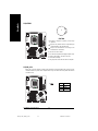
Before installing the memory modules, adhere to the following warning:
1.When DIMM LED is ON, do not install / remove DIMM from socket.
2.Please note that the DIMM module can only fit in one direction due to
the one notch. Wrong orientation will cause improper installation.
Please change the insert orientation.
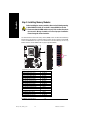
Step 2: Installing Memory Modules
The motherboard has 4 dual inline memory module (DIMM) sockets. The BIOS will automatically
detects memory type and size. To install the memory module, just push it vertically into the DIMM
socket. The DIMM module can only fit in one direction due to the notch. Memory size can vary
between sockets.(*The GA-K8NNXP-940 only support registered DIMM!)
DDR
Notch
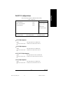
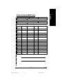
Total Memory Size Per Chip Select
Device Used on DIMMs Size Per CS
64 Mbit (4Mx4-bitsx4 banks) 128 Mbyte
64 Mbit (2Mx8-bitsx4 banks) 64 Mbyte
64 Mbit (1Mx16-bitsx4 banks) 32 Mbyte
128 Mbit(8Mx4-bitsx4 banks) 256 Mbyte
128 Mbit(4Mx8-bitsx4 banks) 128 Mbyte
128 Mbit(2Mx16-bitsx4 banks) 64 Mbyte
256 Mbit(16Mx4-bitsx4 banks) 512 Mbyte
256 Mbit(8Mx8-bitsx4 banks) 256 Mbyte
256 Mbit(4Mx16x4 banks) 128 Mbyte
512 Mbit(32Mx4-bitsx4 banks) 1 Gbyte
512 Mbit(16Mx8-bitsx4 banks) 512 Mbyte
512 Mbit(8Mx16-bitsx4 banks) 256 Mbyte
1 Gbit(64Mx4-bitsx4 banks) 2 Gbyte
1 Gbit(32Mx8-bitsx4 banks) 1 Gbyte
1 Gbit(16Mx16-bitsx4 banks) 512 Mbyte
k8nnxp-940_1001_q.p65 2003/10/2, ¤U¤È 05:1918

Hardware Installation Process
English
- 19 -
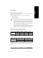
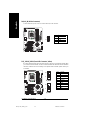
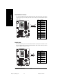
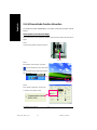
Below are the explanations:
1. One,DDR memory module is installed: The Dual Channel Technology will not operate
when one, DDR memory modules is installed and it will only work as Single Channel.
2. Two DDR memory modules are installed (the same memory size and type): The Dual
Channel Technology will operate when two DDR memory modules are inserted indi-
vidually into Channel A and Channel B (DIMM 1 pairs up with DIMM 2 and DIMM 3, 4).
However, if the two DDR memory modules are inserted into the same Channel (DIMM
1,3 or DIMM 2,4) then Dual Channel Technology will not operate.
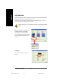
3. If four DDR memory modules are installed (two pairs of DDR memory modules with the
same memory size and type): The Dual Channel Technology will operate when a pair
of DDR memory modules are inserted into DIMM1, 2 and another pair into DIMM 3,4.
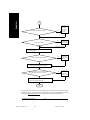
Dual Channel DDR:
GA-K8NNXP-940 supports Dual Channel Technology.
When Dual Channel Technology is activated, the bandwidth of memory bus will be double the original
one,with the fastest speed at 6.4GB/s DDR400.
GA-K8NNXP-940 includes four DIMM slots, and each Channel has 2 DIMMs as following:
Channel A : DIMM 1, 3
Channel B : DIMM 2, 4
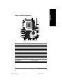
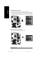
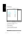
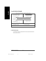
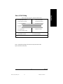
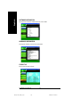
The following tables include all memory-installed combination types:
(Please note that those types not in the tables will not boot up.)
2 memory modules
4 memory modules
DIMM 1 DIMM 2 DIMM 3 DIMM4
DS/SS DS/SS X X
X X DS/SS DS/SS
DS/SS DS/SS DS/SS DS/SS
l Figure 1: Dual Channel Technology (DS: Double Side, SS: Single Side)
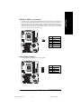
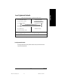
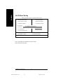
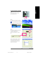
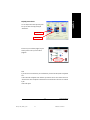
1 memory module
2 memory module
DIMM 1 DIMM 3
DS/SS X
X DS/SS
DS/SS DS/SS
l Figure 2: Don't operate Dual Channel Technology (DS: Double Side, SS: Single Side)
*The K8NNXP-940 don’t support 3 memory modules. If 3 memory modules are inserted, the system will
not boot.
k8nnxp-940_1001_q.p65 2003/10/2, ¤U¤È 05:1919

- 20 -GA-K8NNXP-940 Motherboard
English
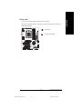
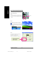
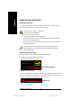
DDR Introduction
Established on the existing SDRAM infrastructure, DDR (Double Data Rate) memory is a high
performance and cost-effective solution that allows easy adoption for memory vendors, OEMs, and
system integrators.
DDR memory is a great evolutionary solution for the PC industry that builds on the existing SDRAM
architecture, yet make the awesome advances in solving the system performance bottleneck by doubling
the memory bandwidth. Nowadays, with the highest bandwidth of 3.2GB/s of DDR400 memory and
complete line of DDR400/333/266/200 memory solutions, DDR memory is the best choice for building
high performance and low latency DRAM subsystem that are suitable for servers, workstations, and full
range of desktop PCs.
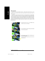
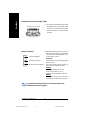
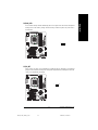
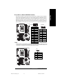
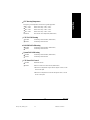
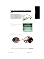
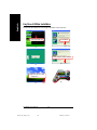
1. The DIMM socket has a notch, so the DIMM memory
module can only fit in one direction.
2. Insert the DIMM memory module vertically into the DIMM
socket. Then push it down.
3. Close the plastic clip at both edges of the DIMM sockets
to lock the DIMM module.
Reverse the installation steps when you wish to remove
the DIMM module.
k8nnxp-940_1001_q.p65 2003/10/2, ¤U¤È 05:1920
La pagina sta caricando ...
La pagina sta caricando ...
La pagina sta caricando ...
La pagina sta caricando ...
La pagina sta caricando ...
La pagina sta caricando ...
La pagina sta caricando ...
La pagina sta caricando ...
La pagina sta caricando ...
La pagina sta caricando ...
La pagina sta caricando ...
La pagina sta caricando ...
La pagina sta caricando ...
La pagina sta caricando ...
La pagina sta caricando ...
La pagina sta caricando ...
La pagina sta caricando ...
La pagina sta caricando ...
La pagina sta caricando ...
La pagina sta caricando ...
La pagina sta caricando ...
La pagina sta caricando ...
La pagina sta caricando ...
La pagina sta caricando ...
La pagina sta caricando ...
La pagina sta caricando ...
La pagina sta caricando ...
La pagina sta caricando ...
La pagina sta caricando ...
La pagina sta caricando ...
La pagina sta caricando ...
La pagina sta caricando ...
La pagina sta caricando ...
La pagina sta caricando ...
La pagina sta caricando ...
La pagina sta caricando ...
La pagina sta caricando ...
La pagina sta caricando ...
La pagina sta caricando ...
La pagina sta caricando ...
La pagina sta caricando ...
La pagina sta caricando ...
La pagina sta caricando ...
La pagina sta caricando ...
La pagina sta caricando ...
La pagina sta caricando ...
La pagina sta caricando ...
La pagina sta caricando ...
La pagina sta caricando ...
La pagina sta caricando ...
La pagina sta caricando ...
La pagina sta caricando ...
La pagina sta caricando ...
La pagina sta caricando ...
La pagina sta caricando ...
La pagina sta caricando ...
La pagina sta caricando ...
La pagina sta caricando ...
La pagina sta caricando ...
La pagina sta caricando ...
La pagina sta caricando ...
La pagina sta caricando ...
La pagina sta caricando ...
La pagina sta caricando ...
La pagina sta caricando ...
La pagina sta caricando ...
La pagina sta caricando ...
La pagina sta caricando ...
La pagina sta caricando ...
La pagina sta caricando ...
La pagina sta caricando ...
La pagina sta caricando ...
La pagina sta caricando ...
La pagina sta caricando ...
La pagina sta caricando ...
La pagina sta caricando ...
La pagina sta caricando ...
La pagina sta caricando ...
La pagina sta caricando ...
La pagina sta caricando ...
La pagina sta caricando ...
La pagina sta caricando ...
La pagina sta caricando ...
La pagina sta caricando ...
La pagina sta caricando ...
La pagina sta caricando ...
La pagina sta caricando ...
La pagina sta caricando ...
La pagina sta caricando ...
La pagina sta caricando ...
La pagina sta caricando ...
La pagina sta caricando ...
-
 1
1
-
 2
2
-
 3
3
-
 4
4
-
 5
5
-
 6
6
-
 7
7
-
 8
8
-
 9
9
-
 10
10
-
 11
11
-
 12
12
-
 13
13
-
 14
14
-
 15
15
-
 16
16
-
 17
17
-
 18
18
-
 19
19
-
 20
20
-
 21
21
-
 22
22
-
 23
23
-
 24
24
-
 25
25
-
 26
26
-
 27
27
-
 28
28
-
 29
29
-
 30
30
-
 31
31
-
 32
32
-
 33
33
-
 34
34
-
 35
35
-
 36
36
-
 37
37
-
 38
38
-
 39
39
-
 40
40
-
 41
41
-
 42
42
-
 43
43
-
 44
44
-
 45
45
-
 46
46
-
 47
47
-
 48
48
-
 49
49
-
 50
50
-
 51
51
-
 52
52
-
 53
53
-
 54
54
-
 55
55
-
 56
56
-
 57
57
-
 58
58
-
 59
59
-
 60
60
-
 61
61
-
 62
62
-
 63
63
-
 64
64
-
 65
65
-
 66
66
-
 67
67
-
 68
68
-
 69
69
-
 70
70
-
 71
71
-
 72
72
-
 73
73
-
 74
74
-
 75
75
-
 76
76
-
 77
77
-
 78
78
-
 79
79
-
 80
80
-
 81
81
-
 82
82
-
 83
83
-
 84
84
-
 85
85
-
 86
86
-
 87
87
-
 88
88
-
 89
89
-
 90
90
-
 91
91
-
 92
92
-
 93
93
-
 94
94
-
 95
95
-
 96
96
-
 97
97
-
 98
98
-
 99
99
-
 100
100
-
 101
101
-
 102
102
-
 103
103
-
 104
104
-
 105
105
-
 106
106
-
 107
107
-
 108
108
-
 109
109
-
 110
110
-
 111
111
-
 112
112


