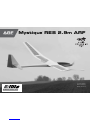
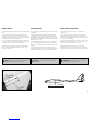
Horizon Hobby Mystique RES 2.9m ARF Manuale utente
- Categoria
- Giocattoli telecomandati
- Tipo
- Manuale utente


2
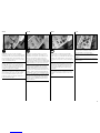
Safety warningS and precautionS
Read and follow all instructions and safety precautions
before use. Improper use can result in fire, serious injury
and damage to property.
Components
Use only with compatible components. Should any
compatibility questions exist, please refer to the product
instructions, component instructions or contact the
appropriate Horizon Hobby office.
Flight
Fly only in open areas to ensure safety. It is
recommended flying be done at radio control flying
fields. Consult local ordinances before choosing a flying
location.
Propeller
Keep loose items that can become entangled in
the propeller away from the prop. This includes
loose clothing or other objects such as pencils and
screwdrivers. Keep your hands away from the propeller
as injury can occur.
Batteries
Always follow the manufacturer’s instructions when using
and disposing of any batteries. Mishandling of Li-Po
batteries can result in fire causing serious injury and
damage.
Small Parts
This kit includes small parts and should not be left
unattended near children as choking and serious injury
could result.
Safe operating recommendationS
• Inspect your model before every flight to ensure it is
airworthy.
• Be aware of any other radio frequency user who may
present an interference problem.
• Always be courteous and respectful of other users in
your selected flight area.
• Choose an area clear of obstacles and large enough to
safely accomodate your flying activity.
• Make sure this area is clear of friends and spectators
prior to launching your aircraft.
• Be aware of other activities in the vicinity of your flight
path that could cause potential conflict.
• Carefully plan your flight path prior to launch.
• Abide by any and all established AMA National Model
Aircraft Safety Code.
NOTICE
All instructions, warranties and other collateral documents are subject to change at the sole discretion of Horizon
Hobby, Inc. For up-to-date product literature, visit horizonhobby. com and click on the support tab for this product.
Meaning of Special Language
The following terms are used throughout the product literature to indicate various levels of potential harm when
operating this product:
NOTICE: Procedures, which if not properly followed, create a possibility of physical property damage AND a little
or no possibility of injury.
CAUTION: Procedures, which if not properly followed, create the probability of physical property damage AND a
possibility of serious injury.
WARNING: Procedures, which if not properly followed, create the probability of property damage, collateral
damage, and serious injury OR create a high probability of superficial injury.
WARNING: Read the ENTIRE instruction manual to become familiar with the features of the product
before operating. Failure to operate the product correctly can result in damage to the product, personal
property and cause serious injury.
This is a sophisticated hobby product. It must be operated with caution and common sense and requires some
basic mechanical ability. Failure to operate this Product in a safe and responsible manner could result in injury
or damage to the product or other property. This product is not intended for use by children without direct adult
supervision. Do not use with incompatible components or alter this product in any way outside of the instructions
provided by Horizon Hobby, Inc. This manual contains instructions for safety, operation and maintenance. It is
essential to read and follow all the instructions and warnings in the manual, prior to assembly, setup or use, in
order to operate correctly and avoid damage or serious injury.
Age Recommendation: Not for children under 14 years. This is not a toy.
USING THE MANUAL
This manual is divided into sections to help make assembly easier to understand. Boxes () have been placed next
to each step. These help keep track of steps that have been completed.

3
warnungen und Sicherheit-
Svorkehrungen
Bitte lesen und befolgen Sie alle Anweisungen und
Sichervorkehrungen vor dem Gebrauch. Falscher,
nicht sachgemäßer Gebrauch kann Feuer, ernsthafte
Verletzungen und Sachbeschädigungen zur Folge haben.
Komponenten
Verwenden Sie mit dem Produkt nur kompatible
Komponenten. Sollten Fragen zur Kompatibilität
auftreten, lesen Sie bitte die Produkt- oder
Bedienungsanweisung oder kontaktieren den Service von
Horizon Hobby.
Fliegen
Fliegen Sie um Sicherheit garantieren zu können, nur
in weiten offenen Gegenden. Wir empfehlen hier den
Betrieb auf zugelassenen Modellflugplätzen. Bitte
beachten Sie lokale Vorschriften und Gesetze, bevor Sie
einen Platz zum Fliegen wählen.
Propeller
Halten Sie lose Gegenstände die sich im Propeller
verfangen können weg vom Propeller. Dieses gilt auch
für Kleidung oder andere Objekte wie zum Beispiel Stifte
oder Schraubendreher.
Halten Sie ihre Hände weg vom Propeller, es besteht
akute Verletzungsgefahr.
Akkus
Folgen Sie immer den Herstelleranweisungen bei
dem Gebrauch oder Entsorgung von Akkus. Falsche
Behandlung von LiPo Akkus kann zu Feuer mit
Körperverletzungen und Sachbeschädigung führen.
Kleinteile
Dieser Baukasten beinhaltet Kleinteile und darf nicht
unbeobachtet in der Nähe von Kindern gelassen werden,
da die Teile verschluckt werden könnten mit ernsthaften
Verletzung zur Folge.
empfehlungen zum Sicheren
BetrieB
• Überprüfen Sie zur Flugtauglichkeit ihr Modell vor
jedem Flug.
• Beachten Sie andere Piloten deren Sendefrequenzen
ihre Frequenz stören könnte.
• Begegnen Sie anderen Piloten in ihrem Fluggebiet
immer höflich und respektvoll.
• Wählen Sie ein Fluggebiet, dass frei von Hindernissen
und groß genug ist.
• Stellen Sie vor dem Start sicher, dass die Fläche frei
von Freunden und Zuschauern ist.
• Beobachten Sie den Luftraum und andere Flugzeuge/
Objekte die ihren Flugweg kreuzen und zu einem
Konflikt führen könnten.
• Planen Sie sorgfältig ihren Flugweg vor dem Start.
HINWEIS
Alle Anweisungen, Garantien und anderen zugehörigen Dokumente können im eigenen Ermessen von Horizon
Hobby, Inc. jederzeit geändert werden. Die aktuelle Produktliteratur finden Sie auf horizonhobby.com unter der
Registerkarte „Support“ für das betreffende Produkt.
Spezielle Bedeutungen
Die folgenden Begriffe werden in der gesamten Produktliteratur verwendet, um auf unterschiedlich hohe
Gefahrenrisiken beim Betrieb dieses Produkts hinzuweisen:
HINWEIS: Wenn diese Verfahren nicht korrekt befolgt werden, können sich möglicherweise Sachschäden UND
geringe oder keine Gefahr von Verletzungen ergeben.
ACHTUNG: Wenn diese Verfahren nicht korrekt befolgt werden, ergeben sich wahrscheinlich Sachschäden UND
die Gefahr von schweren Verletzungen.
WARNUNG: Wenn diese Verfahren nicht korrekt befolgt werden, ergeben sich wahrscheinlich Sachschäden,
Kollateralschäden und schwere Verletzungen ODER mit hoher Wahrscheinlichkeit oberflächliche Verletzungen.
WARNUNG: Lesen Sie die GESAMTE Bedienungsanleitung, um sich vor dem Betrieb mit den
Produktfunktionen vertraut zu machen. Wird das Produkt nicht korrekt betrieben, kann dies zu Schäden am
Produkt oder persönlichem Eigentum führen oder schwere Verletzungen verursachen.
Dies ist ein hochentwickeltes Hobby-Produkt. Es muss mit Vorsicht und gesundem Menschenverstand betrieben
werden und benötigt gewisse mechanische Grundfähigkeiten. Wird dieses Produkt nicht auf eine sichere und
verantwortungsvolle Weise betrieben, kann dies zu Verletzungen oder Schäden am Produkt oder anderen
Sachwerten führen. Dieses Produkt eignet sich nicht für die Verwendung durch Kinder ohne direkte Überwachung
eines Erwachsenen. Verwenden Sie das Produkt nicht mit inkompatiblen Komponenten oder verändern es in
jedweder Art ausserhalb der von Horizon Hobby, Inc. vorgegebenen Anweisungen. Diese Bedienungsanleitung
enthält Anweisungen für Sicherheit, Betrieb und Wartung. Es ist unbedingt notwendig, vor Zusammenbau,
Einrichtung oder Verwendung alle Anweisungen und Warnhinweise im Handbuch zu lesen und zu befolgen, damit es
bestimmungsgemäß betrieben werden kann und Schäden oder schwere Verletzungen vermieden werden.
Nicht geeignet für Kinder unter 14 Jahren. Dies ist kein Spielzeug.
ÜBER DIESE ANLEITUNG
Diese Anleitung ist zur Vereinfachung des Zusammenbaues in Sektionen unterteilt. Neben den Sektionen befinden
sich Kästchen () die es Ihnen leichter machen den Arbeitsschritt als erledigt abzuhaken.

4
avvertimenti e precauzioni per la
Sicurezza
Prima dell’uso leggere attentamente tutte le istruzioni
e le precauzioni per la sicurezza. In caso contrario si
potrebbero procurare incendi, danni o ferite.
Componenti
Usare solo componenti compatibili. Se ci fossero dubbi
riguardo alla compatibilità, è opportuno far riferimento
alle istruzioni relative al prodotto o ai componenti oppure
rivolgersi al reparto Horizon Hobby di competenza.
Volo
Per sicurezza volare solo in aree molto ampie. Meglio
se si va su campi volo autorizzati per modellismo.
Consultare le ordinanze locali prima di scegliere una
ubicazione.
Elica
Tenere gli oggetti liberi (vestiti, penne, cacciaviti, ecc.)
lontano dall’elica, prima che vi restino impigliati. Bisogna
fare attenzione anche con le mani perché c’è il rischio di
ferirsi anche gravemente.
Batterie
Quando si maneggiano o si utilizzano le batterie, bisogna
attenersi alle istruzioni del costruttore; il rischio è di
procurare incendi, specialmente con le batterie LiPo, con
danni e ferite serie.
Piccole parti
Questo kit comprende delle parti di piccole dimensioni
e non lo si può lasciare incustodito se c’è la presenza di
bambini che li possono inghiottire e rimanere soffocati o
intossicati.
raccomandazioni per operare in
Sicurezza
• Controllare attentamente il modello prima di ogni volo
per accertarsi che sia idoneo.
• Essere consapevoli che un altro utente della frequenza
in uso, potrebbe procurare delle interferenze.
• Essere sempre cortesi e rispettosi nei confronti degli
altri utilizzatori dell’area in cui ci si trova.
• Scegliere un’area libera da ostacoli e abbastanza
ampia da permettere lo svolgimento del volo in
sicurezza.
• Prima del volo verificare che l’area sia libera da amici
e spettatori.
• Stare attenti alle altre attività che si svolgono in
vicinanza della vostra traiettoria di volo, per evitare
possibili conflitti.
• Pianificare attentamente il volo prima di lanciare il
modello.
• Rispettare sempre scrupolosamente le regole stabilite
dall’associazione locale.
AVVISO
Tutte le istruzioni, le garanzie e gli altri documenti pertinenti sono soggetti a cambiamenti a totale discrezione di
Horizon Hobby, Inc. Per una documentazione aggiornata sul prodotto, visitare il sito www.horizonhobby.com e fare
clic sulla sezione Support per questo prodotto.
Significato dei termini particolari
In tutta la documentazione relativa al prodotto sono utilizzati iseguenti termini per indicare vari livelli di potenziale
pericolo durante il funzionamento:
AVVISO: Procedure che, se non sono seguite correttamente, possono creare danni materiali E nessuna
oscarsa possibilità di lesioni.
ATTENZIONE: Procedure che, se non sono seguite correttamente, possono creare danni materiali E possibili
gravi lesioni.
AVVERTENZA: Procedure che, se non debitamente seguite, espongono alla possibilità di danni alla proprietà
fisica opossono omportare un’elevata possibilità di provocare ferite superficiali. Ulteriori precauzioni per la
sicurezza e avvertenze.
AVVERTENZA: Leggere TUTTO il manuale di istruzioni e prendere familiarità con le caratteristiche del
prodotto, prima di farlo funzionare. Un utilizzo scorretto del prodotto può causare danni al prodotto stesso,
alle persone oalle cose, provocando gravi lesioni.
Questo è un prodotto di hobbistica sofisticato e NON un giocattolo. È necessario farlo funzionare con cautela e
responsabilità e avere conoscenze basilari di meccanica. Se questo prodotto non è utilizzato in maniera sicura
e responsabile potrebbero verificarsi lesioni odanni al prodotto stesso oad altre proprietà. Non è un prodotto
adatto aessere utilizzato dai bambini senza la diretta supervisione di un adulto. Non usare componenti non
compatibili o alterare il prodotto in nessuna maniera al di fuori delle istruzioni fornite da Horizon Hobby, Inc. Questo
manuale contiene le istruzioni per un funzionamento e una manutenzione sicuri. È fondamentale leggere e seguire
tutte le istruzioni e le avvertenze del manuale prima di montare, configurare ofar funzionare il Prodotto, al fine di
utilizzarlo correttamente e di evitare danni olesioni gravi.
Almeno 14 anni. Non è un giocattolo.
COME USARE IL MANUALE
Questo manuale è diviso in sezioni per rendere più facile la comprensione del montaggio. Vicino ad ogni passo sono
stati posti dei piccoli quadrati () per aiutare a tenere traccia delle cose fatte e di quelle da fare.

5
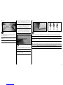
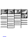
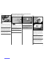
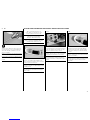
BEFORE STARTING ASSEMBLY
• Remove parts from bag.
• Inspect fuselage, wing panels, rudder and stabilator for damage.
• If you find damaged or missing parts, contact your place of purchase.
If you find any wrinkles in the covering, use a heat gun (HAN100) and
covering glove (HAN150) or covering iron (HAN101) with a sealing iron sock
(HAN141) to remove them. Use caution while working around areas where
the colors overlap to prevent separating the colors.
• Charge transmitter and receiver batteries.
• Center trims and sticks on your transmitter.
• For a computer radio, create a model memory for this particular model.
• Bind your transmitter and receiver, using your radio system’s instructions.
IMPORTANT: Rebind the radio system once all control throws are set.
This will keep the servos from moving to their endpoints until the transmitter
and receiver connect. It will also guarantee the servo reversal settings are
saved in the radio system.
VOR DEM ZUSAMMENBAU
• Entnehmen Sie zur Überprüfung jedes Teil der Verpackung.
• Überprüfen Sie den Rumpf, Tragflächen, Seiten- und Höhenruder auf
Beschädigung.
• Sollten Sie beschädigte oder fehlende Teile feststellen, kontaktieren Sie
bitte den Verkäufer.
Zum Entfernen von Falten in der Bespannung verwenden Sie den Heißluftfön
(HAN100) und Bespannhandschuh (HAN150) oder das Folienbügeleisen
(HAN141). Bitte achten Sie bei überlappenden Farben, dass Sie diese sich
bei dem Bearbeitung nicht trennen.
• Laden des Senders und Empfängers.
• Zentrieren der Trimmungen und Sticks auf dem Sender.
• Sollten Sie einen Computersender verwenden, resetten Sie einen
Speicherplatz und benennen ihn nach dem Modell.
• Sender und Empfänger jetzt nach den Bindeanweisung des Herstellers zu
binden.
WICHTIG: Wir empfehlen dringend nachdem alle Einstellungen
vorgenommen worden sind, das Modell neu zu binden. Dieses verhindert,
dass die Servos in die Endanschläge laufen bevor sich Sender und Empfänger
verbunden haben. Es garantiert auch, dass die Servoreverseeinstellungen in
der RC Anlage gesichert sind.
PRIMA DI INIZIARE IL MONTAGGIO
• Togliere tutti i pezzi dalla scatola.
• Verificare che la fusoliera, l’ala e i piani di coda non siano danneggiati.
• Se si trovano parti danneggiate, contattare il negozio da cui è stato
acquistato.
Se si trovano delle pieghe nella ricopertura, si possono togliere usando una
pistola ad aria calda (HAN100) e guanto per ricopertura (HAN150), oppure
un ferro per ricopertura (HAN101) con la sua calza di protezione (HAN141).
Usare cautela quando si lavora in aree del rivestimento dove ci sono dei
colori sovrapposti, per evitare la loro separazione.
• Caricare il trasmettitore e la batteria di volo.
• Centrare stick e trim sul trasmettitore.
• Con una radio computerizzata creare una nuova memoria per questo
modello.
• Facendo riferimento alle istruzioni del radiocomando, connettere (bind)
trasmettitore e ricevitore.
IMPORTANTE: Ripetere la procedura di connessione una volta regolate
le corse, per evitare che i servi vadano a fine corsa. Garantirà anche che le
impostazioni di inversione del servo vengano salvate nel sistema radio.
Metal Clevis
Gabelkopf
Forcella metallica
Machine screw
Maschinenschraube
Vite per metallo
Self-Tapping Washer-Head Screw
Schraube mit Unterlegscheibenkopf
Vite autofilettante flangiata
Hex Nut
Sechskantmutter
Dado esagonale
Pushrod Keeper
Sicherungsclip
Fermo per asta di comando
M

6
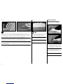
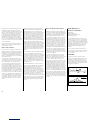
114 in (2.90 m)
1030 sq in (66.5 dm2)
58.5 in (1.48 m)
4.85–5.00 lb (2.20–2.25 kg)
Electric Power: Power 25 Brushless, 1000Kv
Elektro Antrieb: Power 25 Brushless, 1000Kv
Motore elettrico Power: 25 Brushless, 1000Kv
4-channel (or greater) with 4 servos
4-Kanal (oder größer) mit 4-Servos
a 4 canali (o più) con 4 servo
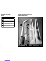
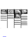
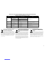
SPECIFICHE
SCHEMA DEI COMPONENTI GRANDI
6
2 1
3
4
3
5
7
8

7
Part English Deutsch Italiano
1. EFL491501 Right Wing Panel Tragfläche rechts Semiala destra
2. EFL491502 Left Wing Panel Tragfläche links Semiala sinistra
3. EFL491503 Fuselage Rumpf Fusoliera
4. EFL491504 Rudder Seitenruder Timone
5. EFL491505 Stabilator Höhenruder Stabilizzatore
6. EFL491508 Wing Rod Flächenverbinder Baionetta ala
7. EFL491509 Stabilator Rods Höhenruderverbinder Aste stabilizzatore
8. EFL490510 Canopy Kabinenhaube Capottina
EFL491506 Hardware Pack A Kleinteilepaket A Viti e accessori pacl a
EFL491507 Hardware Pack B Kleinteilepaket B Viti e accessori pack b
SPMAR7010 AR7010 7-Channel DSMX® Receiver AR7010 6-Kanal DSMX Empfänger AR7010 ricevitore DSMX a 6 canali
SPMSA4020 (2) A4020 Micro Digital Metal Gear Servo A4020 Micro Dig. Flug - Servo Metallgetriebe A4020 Micro servo digitale ingranaggi metallo
SPMSA7020 (2) A7020 Digital Wing Servo A7020 Digitales Tragflächenservo A7020 Servo digitale per ala
SPMA3058 Standard Y-Harness, 6-inch Spektrum Hochleistungs Y-Servokabel Collegamento a Y standard, 152mm
SPMA3052 (4) Servo Extension, 9-inch (228mm) Servokabelverlängerung 22.8 cm (9 inch) Collegamenti servo 9 pollici
EFLM4025C Power 25 Brushless Outrunner, 1000Kv Power 25 BL Aussenläufer Motor, 1000Kv Power 25 BL motore Outrunner, 1000Kv
EFLA1060 60-Amp Pro Brushless ESC 60-A Pro SB Brushless Regler 60-Amp Pro SB ESC Brushless
EFLB32003S30 3200mAh 3S 11.1V 30C Li-Po, 12AWG EC3™ 3200mAh 3S 11,1V 30C LiPo Akku, 12AWG EC3 Connettore EC3 3200 mAh 3S 11,1V 30C Li-Po, 12 AWG
EFLP14080FA 14x8 Folding Propeller with Aluminum Spinner, 40mm 14 x 8 Klappluftschraube mit Aluminium Spinner, 40mm Elica Pieghevole 14X8 con ogiva in alluminio, 40mm
Receiver Battery Empfängerakku Batteria ricevitore
Switch Harness Schalterkabel Interruttore
DLMBD38 Liquid Gravity; Weight System Liquid Gravity Weight System Sistema di peso liquido per il centraggio
EFLA110 Power Meter E-flite Lastmessgerät Misuratore di potenza
EFLC3020 Celectra™ 200W DC Charger E-flite 200W DC Multi-Akku Ladegerät Celectra 200W DC Caricabatterie

8
Part English Deutsch Italiano
PAAPT03 Medium CA Sekundenkleber mittel Medio CA
PAAPT09 Thin CA Sekundenkleber dünnflüssig Sottile CA
PAAPT42 Threadlock Schraubensicherungslack Frenafiletti
PAAPT35 15-Minute Epoxy 15 Minuten Epoxy Colla epoxy 15 minuti
Glue stick Klebestift Stick colla
English Deutsch Italiano
C-clamp Schraubzwinge Morsetto a C
Drill Bohrer Trapano
Drill bit: 1/16-inch, 5/64-inch Bohrer: 1,5 mm. 2mm Punte per trapano: 1,5 mm, 2mm
Electrical tape-white Isolierband weiss Nastro elettrico bianco
Felt-tipped pen Faserstift Pennarello
Hemostat Klemme Pinzetta
Hobby and craft square Rechteck Squadra
Hobby knife: #11 blade Hobbymesser mit # 11 Klinge Taglierino: #11 lama
Isopropyl alcohol Isopropyl Alkohol Alcol isopropilico
Low-tack tape Klebeband m. geringer Klebekraft Nastro a bassa aderenza
Paper towels Papiertücher Asciugamani di carta
Pencil Stift Matita
Petroleum jelly Vaseline Vaselina
Phillips screwdriver: #1, #2 Phillips Schraubendreher: #1,#2 Cacciavite a croce: #1, #2
Pin vise Handbohrer Trapano manuale
Pliers Spitzzange Pinze
Ruler Lineal Righello
Sandpaper Schleifpapier Carta vetrata
Scissors Schere Forbici
Side cutters Seitenschneider Lama laterale
Toothpicks Zahnstocher Stuzzicadenti

9
15
30
OIL
L
R
L
R
x2
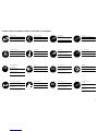
Use a pencil
Verwenden Sie einen Bleistift
Usare una matita
Use medium CA
Mittelflüssigen
Sekundenkleber verwenden
Usare colla ciano acrilica media
Use thin CA
Dünnflüssigen
Sekundenkleber verwenden
Usare colla ciano acrilica fine
Use a felt-tipped pen
Verwenden Sie einen Faserstift
Usare un pennarello
Use 15-minute epoxy
Verwenden Sie 15 Minuten Epoxy
Usare una resina epossidica con
indurimento di 15 minuti
Ensure free rotation
Rotation sicherstellen
Assicurarsi rotazione libera
Push tightly
Fest drücken
Spingere forte
Apply oil
Öl verwenden
Applicare olio
Attach temporarily
Vorübergehend anbringen
Attaccare temporaneamente
Apply threadlock
Schraubensicherungslack verwenden
Applicare fuido threadlock
Assemble right and left
Links und rechts montieren
Assemblare destra e sinistra
Repeat multiple times
(as indicated)
Vorgang wiederholen
(wie angezeigt)
Ripetere piu’ volte
(come indicato)
Ensure proper orientation
Ausrichtung/Richtung sicherstellen
Assicurarsi dell’appropriato
orientamento
Use 30-minute epoxy
Verwenden Sie 30 Minuten Epoxy
Usare una resina epossidica con
indurimento di 30 minuti
Fully tighten
Vollständig festziehen/festschrauben
Stringere al massimo
Use hobby knife with
#11 blade
Verwenden Sie ein Hobbymesser mit
# 11 Klinge
Usare taglierino per hobbistica con
lama numero 11

10
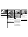
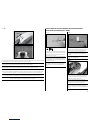
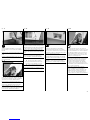
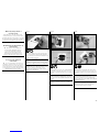
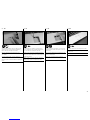
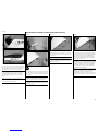
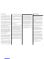
1
Use sandpaper to lightly sand the bottom of the control
horn where it fits into the rudder. Remove any dirt
and oils from the control horn using a paper towel and
isopropyl alcohol.
Schleifen Sie die Unterseite des Rudershornes dort
an wo es Kontakt mit dem Ruder hat. Entfernen Sie
mit Reinigungsalkohol und einem Papiertuch sämtliche
Verschmutzungen.
Scartavetrare leggermente la squadretta sulla parte che
sarà incollata. Con alcool e un fazzoletto di carta togliere
unto e sporcizia dalla parte carteggiata.
ÎThe rudder horn has a hole at the bottom, while
the spoiler control horns have the bottoms trimmed.
Make sure to use the correct horn for the rudder.
ÎDas Seitenruderhorn hat ein Loch an der
Unterseite während die Klappenhörner eine
angeschnittene Unterseite haben. Bitte achten
Sie darauf das richtige Ruderhorn zu wählen.
ÎLa squadretta del timone ha un foro nella
parte inferiore, mentre quelle dello spoiler
hanno la parte inferiore rifilata. Occorre fare
attenzione a usare la squadretta corretta.
2
Place low-tack tape so it is spaced 1/32 inch (1mm)
from the base of the control horn. This will prevent epoxy
from getting on the rudder surface when the control horn
is glued in place.
Kleben Sie Kreppband in 1mm Abstand zur
Ruderhornöffnung auf. So verhindern Sie, dass beim
Kleben Epoxy auf die Oberfläche des Seitenruders
gelangt.
Mettere del nastro a bassa adesività ad 1mm dalla base
della squadretta per proteggere il timone dalla colla
eccedente.
3
15
Mix a small amount of 15-minute epoxy. Use a toothpick
to apply epoxy in the slot for the control horn, and to the
area of the control horn that fits into the rudder. Fit the
control horn in the rudder. The horn will fit snug in the
slot. Use a paper towel and isopropyl alcohol to remove
any excess epoxy from around the control horn. Before
the epoxy fully cures, remove the tape from around the
control horn.
Mischen Sie etwas 15 Minuten Epoxy an. Geben Sie
mit einem Zahnstocher Epoxy in den Schlitz und auf die
Fläche des Ruderhorns das eingepaßt wird. Das Horn
paßt saugend in das Ruder. Wischen Sie überschüssigen
Klebstoff mit Reinigungsalkohol und einem Papiertuch
ab. Entfernen Sie das Klebeband bevor der Klebstoff
vollständig getrocknet ist.
Mescolare una piccola quantità di colla epoxy 15 minuti e
applicarla con uno stuzzicadenti sulla squadretta e nella
fessura in cui andrà inserita. Inserire la squadretta nel
timone in cui entrerà con perfetta aderenza. Con alcool
e un fazzoletto di carta togliere la colla epoxy in eccesso
intorno alla squadretta. Prima che la colla si asciughi
togliere il nastro messo intorno alla squadretta.
INCERNIERARE IL TIMONE
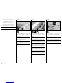
1
Remove the stabilator bellcrank cover from the fuselage.
Set it aside in a safe location until it is required later in
this manual.
Nehmen Sie die hintere Leitwerksklappe vom Rumpf ab
und legen diese zur Seite.Die Klappe wird erst später
wieder benötigt.
Togliere il coperchio della squadretta dello stabilizzatore.
Metterlo da parte in un luogo sicuro poiché servirà più
avanti.

11
2
x4
Use a toothpick to apply a small amount of petroleum
jelly to the flex point of the hinge. This will prevent epoxy
from entering the hinge.
Geben Sie mit einem Zahnstocher etwas Vaseline auf das
Drehgelenk des Scharnieres. Das verhindert eindringen
von Epoxy.
Mettere una piccola quantità di vaselina sullo snodo della
cerniera per evitare che la colla lo blocchi.
ÎThe following steps outline the installation of the
rudder hinges. Their alignment must be correct for
the rudder to move through its full range of motion.
Do not use any epoxy on the hinges until instructed.
ÎDie folgenden Schritte beschreiben den
Einbau der Seitenruderscharniere. Damit
sich das Ruder richtig bewegen kann müssen
die Scharniere korrekt ausgerichtet sein.
Bitte kleben Sie erst nach Anweisung.
ÎI passaggi seguenti illustrano l’installazione
delle cerniere del timone. Il loro allineamento deve
essere corretto, altrimenti il timone non potrà
avere tutta la sua corsa. Non mettere colla sulle
cerniere finché non verrà detto espressamente.
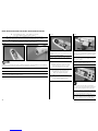
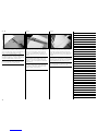
3
Position the hinges such that, when deflected, they are
perpendicular to the hinge line of the control surface.
Positionieren Sie die Scharniere so, dass wenn dieses
gekippt sind im rechten Winkel zum Ruder stehen.
Posizionare le cerniere in modo che, quando vengono
deflesse, restino perpendicolari alla linea di cerniera
della superficie di controllo.
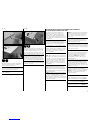
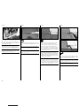
4
Position the hinge so the pin is aligned with the center of the leading edge radius. Each hinge must be positioned
individually, as the radius changes along the length of the control surface.
Positionieren Sie das Scharnier so dass das Gelenk in der Mitte des Kantenradius ist. Jedes Scharnier muß individuell
positioniert werden, da sich der Radius ändert.
Posizionare la cerniera in modo che il suo perno sia allineato con il centro del raggio del bordo di entrata. Ogni
cerniera deve essere posizionata singolarmente, poiché il raggio cambia lungo l’estensione della superficie di
controllo.
ÎFailure to position the hinges correctly can result in binding of the control surface or limited control throw.
ÎFalsches Ausrichten der Scharniere kann zum Blockieren des Ruders oder zu geringen Ruderausschlag führen.
ÎSe le cerniere non fossero posizionate correttamente si avrebbe un
bloccaggio della superficie di controllo o una sua corsa limitata.

12
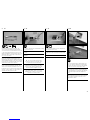
5
Fit the rudder to the fin using the hinges. The gap
between the front edge (leading edge) of the rudder and
fin must be as small as possible.
Passen Sie das Ruder an die Finne mit den drei
Scharnieren an. Der Spalt an der Vorderseite zwischen
Ruder und Finne muß so klein wie möglich sein.
Mettere il timone sul direzionale usando le cerniere. La
fessura tra il bordo di entrata del timone e il direzionale,
deve essere la più piccola possibile.
6
Check to make sure the rudder can move freely through
its full range of motion BEFORE gluing the hinges. If not,
check the hinge alignment to correct any problems.
Überprüfen Sie ob sich das Ruder frei bewegen kann
BEVOR Sie die Scharniere einkleben. Falls nicht,
überprüfen Sie die Ausrichtung der Scharniere um das
Problem zu korrigieren.
Prima di incollare le cerniere, verificare che il timone
si muova liberamente e su tutta la sua corsa. In caso
contrario verificare l’allineamento delle cerniere per
correggere il problema.
7
x4
15
Once the positioning of the hinges has been determined,
remove the rudder from the fin and remove the hinges
from the rudder. Mix 1/8 ounce (3.55 ml) of 15-minute
epoxy. Apply the epoxy in the holes for the hinges in the
rudder and to the area of the hinge that fits into the
rudder.
Haben Sie die Scharnierpositionen festgelegt, nehmen
Sie das Ruder von der Finne und entfernen die
Scharniere. Mischen Sie ca. 3,6ml 15 Minuten Epoxy
und geben dieses in die Löcher am Ruder und auf die
Enden der Scharniere wo sie in das Ruder gesteckt
werden.
Dopo aver posizionato le cerniere, togliere il timone dal
direzionale e le cerniere dal timone. Miscelare un po’ di
colla epoxy 15 minuti e metterla nei fori per le cerniere e
sulla parte delle cerniere che entra nel timone.
8
x4
Fit the epoxy-covered hinges into the rudder. Make sure
they are aligned as described, then use a paper towel
and isopropyl alcohol to remove any excess epoxy that
may interfere with the operation of the rudder. Allow the
epoxy to fully cure before proceeding.
Setzen Sie die mit Epoxy bestrichenen Scharniere in das
Ruder ein. Stellen Sie sicher, dass diese wie beschrieben
ausgerichtet sind und wischen überschüssigen Klebstoff
der die Funktion beeinflussen könnte mit einem
Papiertuch und Reinigungsalkohol weg.
Inserire nel timone le cerniere con la colla, accertandosi
che siano allineate correttamente. Togliere poi la colla
in eccesso con alcool e un fazzoletto di carta. Prima di
procedere aspettare che la colla si asciughi.

13
9
x4
15
Mix 1/8 ounce (3.55 ml) of 15-minute epoxy. Apply the
epoxy in the holes for the hinges in the fin and to the
area of the hinge that fits into the fin.
Mischen Sie ca. 3,6ml 15 Minuten Epoxy und geben
dieses in die Löcher an der Finne und auf die Stellen der
Scharniere die in die Finne gesteckt werden.
Usare poi altra colla epoxy 15 minuti per incollare le
cerniere al direzionale.
10
x4
Fit the epoxy-covered hinges into the fin. Make sure the
gap between the rudder and fin is as small as possible.
Use a paper towel and isopropyl alcohol to remove any
excess epoxy that may interfere with the operation of the
rudder. Allow the epoxy to fully cure before proceeding.
Setzen Sie die Epoxy bestrichenen Scharniere in die Finne
ein. Stellen Sie bitte sicher, dass der Spalt zwischen
Finne und Ruder so klein wie möglich ist. Wischen Sie
überschüssigen Klebstoff der die Funktion beeinflussen
könnte mit einem Papiertuch und Reinigungsalkohol weg.
Inserendo il timone nel direzionale accertarsi che la
fessura tra il bordo di entrata del timone e il direzionale,
sia la più piccola possibile.
There are two possible radio configurations for the
Mystique RES. The first is more commonplace to
motorized sailplane, or powered sailplane operation,
and is how we recommend you build the airplane. The
second is an option that some may find better suits their
preferred flying style, especially when moving up from a
powered aircraft.
Es gibt zwei RC Konfigurationen für die Mystique RES.
Die erste Option ist mehr für den Seglerbetrieb und
entspricht unserer Empfehlung das Modell zu bauen. Die
zweite Option richtet sich mehr an die Motorflieger.
Per il Mystique RES ci sono due configurazioni possibili.
La prima è la più comune per la motorizzazione
dell’aliante ed è quella che raccomandiamo. La seconda
opzione è quella che alcuni preferiscono perché è la più
rispondente al loro modo di volare, specialmente se si
ricorre ad un trainatore.
Option 1: This is where the motor is used purely as a
launch method, and is activated by a momentary switch
or other switch or slider. The throttle stick is then used
to activate the spoilers, which are modulated in much
the same way the throttle would be used on a powered
airframe to control the descent rate. This provides a
natural and intuitive way to control the model’s descent
rate and landing.
Option 1: Hier wird der Motor nur als Starthilfe
genutzt und wird durch einen Taster, Schalter oder
Schieber aktiviert. Der Gashebel dient zum Stellen der
Klappen in gleicher Weise wie bei einem Motorflugzeug
die Sinkrate reguliert wird. Diese bietet dem Piloten eine
gewohnt intuitive Kontrolle.
Opzione 1: In questo caso si usa il motore solamente
per far salire il modello ed è attivato con un interruttore
o un cursore. Lo stick del motore viene usato per
attivare gli spoiler, che in questo modo sono modulati nel
migliore dei modi per regolare la discesa e l’atterraggio
in modo naturale e intuitivo.
Option 2: In this setup the throttle is activated by the
throttle stick, allowing the model to be flown at various
throttle settings in the same manner as a powered
airplane. The spoilers would then be operated by a
switch or slider.
Option 2: In dieser Einstellung ist das Gas über den
Gashebel aktiviert und das Modell fliegt sich wie ein
Motorflugzeug. Die Klappen werden dann über einen
Schalter oder Schieber angesteuert.
Opzione 2: In questa configurazione il motore viene
comandato dallo stick, permettendo di volare con regimi
del motore variabili, proprio come un normale modello a
motore. In questo caso gli spoiler saranno comandati da
un interruttore o da un cursore.
In either case, use extreme caution around the propeller
and check the transmitter switch and throttle stick
positions before connecting the motor battery. We
recommend using Option 1 with the throttle on
a momentary button or switch so that it cannot be
inadvertently activated.
In beiden Konfigurationen sollten Sie im Propellerbereich
extrem vorsichtig sein und grundsätzlich die Stellung
der Schalter und des Gashebel vor dem Anstecken des
Akkus überprüfen. Wir empfehlen die Gasfunktion auf
einen Taster oder Schalter zu legen, so dass diese nicht
zufällig aktiviert werden kann.
In entrambi i casi bisogna stare molto attenti all’elica
e controllare i comandi sul trasmettitore prima di
collegare la batteria del motore. Noi consigliamo di usare
l’Opzione 1 con il motore comandato da un pulsante
momentaneo o da un interruttore in modo da non
attivarlo inavvertitamente.
ÎThe parts and text listed in this manual are
targeted toward building your model using Option 1.
ÎDie Teile und die in dieser Anleitung ausgeführten
Beschreibungen sind für die Option 1.
ÎTutte le parti e i testi di questo manuale sono
orientati a questa versione, cioè con l’Opzione 1.
ReceiveR and SeRvo inStallation•empfängeR und SeRvoeinbau•
inStallazione del ricevitore e del Servo

14
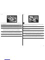
2
Rudder•Seitenruder•Timone
Stabilator•Höhenruder•Elevatore
Use side cutters to trim the remaining arms so they don’t interfere with the operation of the servos. Repeat the
previous step to prepare the stabilator servo. Make sure the servo is plugged into the elevator port of the receiver,
and that the elevator stick and trim are centered before installing the servo arm.
Schneiden Sie die überzählige Arme ab, so dass diese die Servofunktion nicht beeinflussen. Bitte stellen Sie sicher,
dass das Servo in den Höhenruder (Elevator Port) des Empfängers gesteckt ist und das der Steuerhebel und die
Trimmung zentriert sind bevor sie den Arm aufsetzen.
Usare un tronchesino per eliminare i bracci delle squadrette che non vengono utilizzati in modo che non interferiscano
nei movimenti. Preparare allo stesso modo il servo per l’elevatore e collegarlo al corrispondente canale sul ricevitore.
Verificare che stick e trim siano centrati prima di fissare la squadretta sul servo.
1
Install the servo grommets and brass eyelets in the servos. Plug the rudder servo into the aileron port of the receiver.
With the radio system on, make sure the programming has been cleared (if using a computer radio) and that the
aileron stick and trim are centered. Place the servo arm on the servo so it is aligned with the centerline of the servo.
Rotate the arm 90 degrees until the best alignment can be determined.
Setzen Sie die Gummipuffer und Messingösen in die Servos ein. Schließen Sie das Seitenruderservo in den
Querruderanschluss (Aileron) des Empfängers an. Stellen Sie mit eingeschalteter Fernsteuerung sicher, dass
die Programmierung frei und unbenutzt ist (gilt für Computersender) und das die Querrudertrimmung und der
Steuerhebel neutral ist. Setzen Sie den Servoarm so auf, dass er mit der Mittellinie ausgerichtet ist.Drehen Sie den
Servoarm weiter um 90° bis die beste Ausrichtung zur Mittellinie erreicht ist.
Montare sul servo i gommini e i distanziali in ottone. Collegare il servo del timone sul canale degli alettoni. Con
il radiocomando acceso, accertarsi che tutte le programmazioni precedenti siano state azzerate (se si usa un
radiocomando computerizzato e che lo stick degli alettoni e il suo trim siano centrati. Mettere sul servo la sua
squadretta in modo che sia allineata con la sua linea centrale. Ruotare la squadretta fino a determinare il miglior
allineamento.
ÎBecause the Mystique sailplane uses only the elevator and rudder to control the
aircraft in flight, the rudder servo is plugged into the aileron port of the receiver.
ÎDa die Mystique für die Flugsteuerung nur das Höhen und Seitenruder verwendet
wird das Seitenruderservo in den Querruderanschluss des Empfängers gesteckt.
ÎSiccome il Mystique usa solo i controlli di timone ed elevatore, il
servo del timone sarà collegato al canale degli alettoni.

15
3
Fit the rudder servo into the radio tray inside the
fuselage. The output of the servo faces toward the front
of the fuselage. Leave a gap of 1/8-inch (3mm) between
the servo and edge of the servo tray. Hold the servo in
position, and mark the locations for the servo mounting
screws on the plywood radio tray.
Setzen Sie das Seitenruderservo in die Servoplatte im
Rumpf ein. Der Abtrieb des Servos zeigt nach vorne
zur Rumpfspitze. Lassen Sie einen 3mm breiten Spalt
zur Seite der Servoplatte (siehe Pfeil) Halten Sie das
Servo in Position und markieren die Positionen für die
Servohalterschrauben auf der Servoplatte.
Mettere il servo del timone sul supporto radio all’interno
della fusoliera. L’uscita del servo è rivolta verso la parte
anteriore della fusoliera. Lasciare uno spazio di 3mm
tra il servo e il bordo del supporto. Tenere il servo
posizionato e segnare sul compensato del supporto la
posizione delle viti di fissaggio.
4
Remove the servo from the fuselage. Use a pin vise
and 5/64-inch (2mm) drill bit to drill the two holes in
the plywood servo tray for the servo mounting screws.
Thread a servo mounting screw into the two holes
to cut threads in the surrounding wood. Remove the
screw before proceeding to the next step. Apply a small
amount of thin CA into each of the holes. This will harden
the threads made by the screws in the previous step.
Nehmen Sie das Servo aus dem Rumpf heraus. Bohren
Sie mit einem 1,5mm Handbohrer die Löcher für die
Servobefestigungsschrauben. Drehen Sie mit einem
#1 Phillips Schraubendreher eine Servoschraube in die
Löcher. Drehen Sie die Schraube wieder heraus bevor Sie
fortfahren. Geben Sie eine kleine Menge dünnflüssigen
Sekundenkleber in jedes Loch um die Gewinde zu härten.
Togliere il servo dalla fusoliera e con una punta da 2mm
fare i due fori per le viti di fissaggio. Avvitare una vite
nei fori per creare una filettatura e poi toglierla prima
di mettere una piccola quantità di colla CA nei fori per
indurire la filettatura.
5
Place the rudder servo back into the fuselage with
the output of the servo facing toward the front of the
fuselage. Route the servo lead under the radio tray and
through the hole shown in the photo. Secure the servo
in the radio tray using the two screws provided with the
servo.
Setzen Sie das Seitenruderservo in den Rumpf mit
dem Abtrieb in Richtung Rumpfspitze. Führen Sie das
Servokabel unter der Servoplatte und dann durch das
Loch wie im Foto abgebildet. Sichern Sie das Servo in
der Servoplatte mit den beiden Schrauben aus dem
Lieferumfang.
Rimettere il servo del timone in fusoliera con la sua
uscita in avanti. Far passare il cavetto del servo sotto
al supporto e nel foro illustrato. Fissare il servo con le
sue viti.
6
Repeat the steps for installing the rudder servo to
secure the stabilator servo in the fuselage.
Wiederholen Sie die Schritte für den Einbau des
Seitenruderservos um das Höhenruderservo im Rumpf
einzubauen.
Ripetere la stessa procedura per fissare in fusoliera il
servo dell’elevatore.

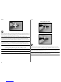
16
9
Place the receiver in the fuselage. Route the lead(s) for
the spoilers under the radio tray and through the holes
behind the servos.
Setzen Sie den Empfänger in den Rumpf ein. Führen Sie
die Kabel für die Klappen unter der Einbauplatte durch
und durch die Rumpföffnungen hinter den Servos nach
draussen.
Piazzare il ricevitore in fusoliera facendo passare i
cavetti per il servo degli spoiler sotto al supporto radio a
attraverso i fori dietro ai servi.
ÎWe used the radio system to move the servo
arms on the rudder and stabilator servos forward to
make sure there is adequate clearance between the
receiver and servos. This prevents the servos from
hitting the receiver during the operation of the model.
ÎWir haben hier mit der Fernsteuerung die
Servoarme nach vorne gefahren um zu überprüfen
dass zwischen Servo und Empfänger ausreichend
Platz ist. Das verhindert dass die Servos den
Empfänger während des Betriebes berühren.
ÎConviene controllare, mettendo in funzione
il radiocomando, che le squadrette dei servi
di timone ed elevatore non vadano a toccare
contro il ricevitore durante il funzionamento.
8
Plug the rudder servo into the aileron port and stabilator
servo into the elevator port of the receiver. Plug a
Y-harness into the throttle (or flap) channel of the
receiver, then connect a 9-inch (228mm) extension to
each of the leads from the Y-harness. Place the hook
portion of the tape to the bottom of the receiver.
Stecken Sie das Servokabel des Seitenruderservos in
die Querruderbuchse des Empfängers. Stecken Sie ein
Y-Kabel in den Gas (Klappen) Kanal und schließen dann
je eine 228mm lange Verlängerung an das Y-Kabel
an. Kleben Sie Hakenseite auf die Unterseite des
Empfängers.
Inserire il servo del timone nel canale degli alettoni
e quello dell’elevatore nel canale dell’elevatore sul
ricevitore. Collegare una prolunga a Y al canale del
motore o a quello dei flap, poi collegare una prolunga da
228mm su ciascun lato della Y. Mettere l’altra parte del
nastro a strappo sul retro del ricevitore.
ÎThe spoilers can be operated using the throttle
channel or the flap channel from your transmitter.
We prefer the use of the throttle channel, as this
allows the amount of spoiler to be varied to control
the decent rate of the model during landings.
ÎDie Klappen können über den Gaskanal
oder über den Klappenkanal des Senders
angesteuert werden. Wir bevorzugen den
Gaskanal, da man damit den Klappenausschlag
bei Landungen feinfühlig steuern kann.
ÎLo spoiler si può comandare dal trasmettitore
sia con il canale del motore che con quello dei flap.
Noi preferiamo il canale del motore poiché permette
di avere un controllo più diretto soprattutto durante
le fasi delicate della discesa e dell’atterraggio.
10
Route the leads for the spoilers through the holes in
the side of the fuselage. Use clear tape to secure the
leads inside the fuselage so they don’t interfere with the
rudder and stabilator pushrod when they are installed
later in this manual.
Führen Sie die Kabel für die Klappen durch die Löcher an
der Rumpfseite nach draussen. Befestigen Sie die Kabel
im Rumpf mit Klebeband so dass sie das Höhen- und
Seitenrudergestänge nicht berühren wenn diese später
eingebaut werden.
Far passare i cavi per gli spoiler attraverso i fori sui
fianchi della fusoliera, fissandoli con del nastro adesivo
all’interno della fusoliera per evitare che vadano ad
interferire con i comandi di timone ed elevatore quando
verranno installati più avanti seguendo questo manuale.
7
Cut two 1/4-inch (6mm) wide pieces from the hook and
loop tape. Apply the loop portion of the tape to the radio
tray.
Schneiden Sie zwei 6mm breite Streifen Klettband
zurecht und kleben die Schlaufenseite auf die
Einbauplatte.
Tagliare due pezzi di nastro a strappo e applicarne uno
sul supporto radio.
ÎPrepare the area for the hook and loop tape
by applying a small amount of medium CA to the
area of the radio tray where the hook and loop
tape will be placed. Remove the excess CA using a
paper towel. Allow the CA to cure before applying
the tape. This will make the tape stick much better
than applying it to the unprepared plywood.
ÎBereiten Sie die Montagefläche mit etwas
Sekundenkleber vor. Entfernen Sie überschüssigen
Kleber mit einem Papiertuch und lassen den
Kleber vollständig trocknen. Dadurch hält das
Klettband erheblich besser als wenn es auf
unbehandeltes Sperrholz geklebt wird.
ÎSul supporto radio preparare l’area dove
applicare il nastro a strappo mettendoci una
piccola quantità di colla CA media. Togliere
l’eccesso di colla con un fazzoletto di carta.
Attendere che la colla si asciughi prima di mettere
il nastro. Tutto questo migliora l’aderenza rispetto
all’applicazione diretta sul legno non preparato.

17
11
1/2 inch
(13mm)
Use hook and loop tape to attach the remote receiver inside the fuselage. Make sure the receiver is back far enough
to allow clearance for the canopy mounting retainer when the canopy is installed.
Befestigen Sie die Satellitenempfänger mit Klettband im Rumpf. Bitte achten Sie darauf dass der Empfänger weit
genug nach hinten befestigt wird um den Kabinenhaubenverschluss nicht zu behindern.
Sempre con nastro a strappo attaccare il ricevitore satellite all’interno della fusoliera. Accertarsi che il ricevitore sia
abbastanza indietro per lasciare spazio al montaggio del fermo per la capottina, quando si dovrà fare.
ÎUse a paper towel and isopropyl alcohol to clean the area for the remote receiver before installing it in the
fuselage. This will remove any debris or oils that may interfere with the adhesion of the hook and loop tape.
ÎReinigen Sie die Klebefläche des Satellitenempfängers mit einem Papiertuch und Reinigungsalkohol
bevor Sie ihn einkleben. Das verhindert dass Verschmutzungen die Haltekraft des Klettband beeinflussen.
ÎPer avere una adesione perfetta, usare un fazzoletto di carta con alcool per pulire
l’area del ricevitore satellite su cui andrà incollato il nastro a strappo.
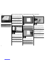
1
x1
M2
x1
M
Thread a nut, then a clevis on the brass fitting that has
been soldered onto the pushrod wire. Thread the clevis
on so the threads from the brass fitting can be seen
between the forks of the clevis.
Drehen Sie zuerst eine Mutter, dann den Gabelkopf auf
die Löthülse die auf das Gestänge gelötet wurde. Drehen
Sie den Gabelkopf so auf, dass das Gewinde zwischen
den Gabeln zu sehen ist.
Avvitare un dado e una forcella sul terminale in ottone
che è già stato saldato sul filo del comando. Avvitare
la forcella finché non si vede la parte filettata al suo
interno.
2
Remove the servo horn from the rudder servo. Attach
the clevis to the servo horn as shown in the photo.
Entfernen Sie das Servohorn vom Seitenruderservo.
Verbinden Sie den Gabelkopf mit dem Servohorn wie
abgebildet.
Togliere la squadretta dal servo del timone e collegarvi la
forcella come si vede dalla foto.
3
Slide the pushrod wire through the tube located in the
fuselage. The pushrod wire will exit at the rear of the
fuselage near the rudder control horn.
Schieben Sie die Anlenkung durch das im Rumpf
befindliche Röhrchen. Die Anlenkung tritt am Rumpfende
in der Nähe des Seitenruderhorns wieder heraus.
Inserire il filo del comando nel suo tubetto guida fissato
all’interno della fusoliera. Il suddetto filo uscirà nella
parte posteriore della fusoliera, vicino alla squadretta del
timone.
INSTALLAZIONE DEL COMANDO PER IL TIMONE

18
4
Place the rudder servo arm back on the rudder servo.
Make sure to use the radio system to verify the servo
arm is installed perpendicular to the servo centerline as
outlined earlier in this manual.
Setzen Sie den Seitenruderservoarm zurück auf
das Seitenruderservo. Stellen Sie mit dem Sender
sicher, dass der Servoarm rechtwinklig zur Mittellinie
ausgerichtet ist wie vorher in der Anleitung beschrieben.
Rimettere sul servo la sua squadretta, avendo cura
di accendere il radiocomando per essere certi che sia
perpendicolare alla linea centrale del servo.
5
Align the rudder with the fuselage centerline. Use care
not to move the rudder accidentally during the next few
steps.
Richten Sie das Seitenruder mit der Rumpfmittellinie
aus. Bitte sein sie vorsichtig das Ruder nicht
versehentlich in den nächsten Schritten zu bewegen.
Allineare il timone con la linea centrale della fusoliera.
Fare attenzione a non muovere accidentalmente il timone
durante i passi seguenti.
6
With the radio system on and the rudder servo and
rudder centered, mark the pushrod wire where it
crosses the hole in the rudder control horn. Carefully
bend the wire 90 degrees at the mark made in the
previous step using pliers. Use side cutters to trim the
wire so 1/4 inch (6mm) of wire remains past the bend
made in the previous step. Insert the wire through the
hole in the rudder control horn.
Markieren Sie mit eingeschalteter Fernsteuerung die
Position am Gestänge auf der Höhe des Lochs im
Ruderhorn. Biegen Sie den Draht vorsichtig um 90°an
der Markierung. Kürzen Sie mit einem Seitenscheider
den Draht nach der Biegung auf 6mm Länge. Stecken Sie
den Draht durch das Ruderhorn.
Con il radiocomando acceso e il timone con il suo servo
centrati, segnare il filo del comando dove incrocia il foro
sulla squadretta del timone. Con delle pinze piegare il
filo a 90° nel punto segnato prima. Usare un tronchesino
per tagliare il filo in eccesso, lasciandone circa 6mm da
inserire nel foro della squadretta del timone.
7
x1
Slide the pushrod keeper on the end of the wire. The slot
in the keeper will snap on the wire, keeping it in position.
Use pliers to snap the keeper into position.
Schieben Sie den Halteclip mit einer Zange auf das Ende
des Drahtes. Der Schlitz im Halteclip fasst um den Draht
und hält ihn so in Position.
Inserire un fermo al termine del filo e agganciarlo ad
esso, aiutandosi magari con delle pinze.

19
8
While the radio is still on, check to make sure the rudder
is centered when the rudder servo is centered. If not,
adjust the clevis at the servo to bring the rudder into
alignment. Once set, use pliers to tighten the nut against
the clevis to prevent it from vibrating loose and changing
position.
Überprüfen Sie mit eingeschalteter Fernsteuerung und
zentriertem Seitenrudersteuerhebel und Servo ob das
Seitenruder zentriert ist. Falls nicht justieren Sie den
Gabelkopf um das Ruder zu zentrieren. Drehen Sie
danach mit einer Zange die Mutter gegen den Gabelkopf
damit sich dieser nicht lösen oder verdrehen kann.
Mantenendo il radiocomando accesso, verificare che il
timone e il relativo servo siano centrati. In caso contrario
regolare la posizione della forcella, stringendole contro il
dado quando la regolazione è terminata.
2
Remove the servo horn from the stabilator servo. Attach
the clevis to the servo horn as shown in the photo.
Nehmen Sie das Servohorn vom Höhenruderservo und
verbinden es mit dem Gabelkopf wie abgebildet.
Togliere la squadretta dal servo dell’elevatore e collegarvi
la forcella come si vede dalla foto.
3
The pushrod can now be inserted into the pushrod tube
near the stabilator servo. The end of the wire will exit
through the stabilator access cover opening. Place the
servo arm back on the servo once the servo has been
centered. Do not put the screw in the servo, as the arm
will need to be removed to bend the pushrod wire later in
this section of the manual.
Führen Sie das Gestänge in das Röhrchen am
Höhenruderservo ein. Das Ende des Gestänges tritt an
der Höhenruderklappe aus. Setzen Sie den Servoarm
nach zentrieren des Servos auf. Schrauben Sie den Arm
jetzt noch nicht fest, da er zum Biegen des Gestänges
später nochmal abgenommen werden muss.
Inserire il filo del comando nel suo tubetto guida fissato
all’interno della fusoliera. Il suddetto filo uscirà nella
parte posteriore della fusoliera, vicino all’elevatore.
Dopo che il servo è stato centrato, rimettergli la sua
squadretta. Non mettere la vite della squadretta
perché dovrà essere ancora rimossa nel prosieguo del
montaggio.
1
x1
M2
x1
M
Thread a nut, then a clevis, on the brass fitting that has
been soldered onto the pushrod wire. Thread the clevis
on so the threads from the brass fitting can be seen
between the forks of the clevis.
Drehen Sie auf die Löthülse des Höhenrudergestänges
die Mutter auf und dann den Gabelkopf, so dass Sie das
Gewinde zwischen den Gabeln sehen können.
Avvitare un dado e una forcella sul terminale in ottone
che è già stato saldato sul filo del comando. Avvitare
la forcella finché non si vede la parte filettata al suo
interno.
INSTALLAZIONE DEL COMANDO PER L’ELEVATORE

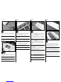
20
4
Use a glue stick (available at a craft store or discount
store) to apply a small amount of adhesive to the first
1 inch (25mm) of the larger carbon stabilator joiner rod.
This will keep the rod secure in the stabilator, yet allow it
to be removed for transport.
Tragen Sie mit einem handelsüblichen Klebestift
etwas Klebstoff auf die ersten 25mm des größeren
Leitwerksverbinder. Das sichert das Leitwerk auf
dem Verbinder, ermöglicht aber zum Transport die
Demontage.
Con uno stick di colla comune, applicare una piccola
quantità di adesivo sui primi 25mm della baionetta
più grande dello stabilizzatore; questo per rendere il
suo inserimento sicuro, ma allo stesso tempo poterla
togliere per il trasporto.
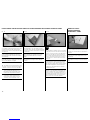
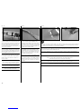
6
Fit the rods into the bellcrank inside the fuselage. Make
sure the smaller rod is inserted into the bellcrank toward
the rudder. Slide the stabilator against the fuselage
so there is a very small gap between the fuselage and
stabilator.
Stecken Sie die Verbinder in den Winkelhebel im Rumpf.
Bitte achten Sie darauf dass der kleinere Verbinder in
den Winkelhebel Richtung Ruder gesteckt wird. Schieben
Sie das Höhenruder an den Rumpf, so dass nur ein sehr
kleiner Spalt zwischen Rumpf und Leitwerk bleibt.
Inserire le baionette nella squadretta che si trova
all’interno della fusoliera, accertandosi che quella più
piccola sia verso il timone. Spingere lo stabilizzatore
contro la fusoliera in modo che ci sia la minima distanza
possibile.
5
Slide the larger and smaller stabilator rods into the
stabilator. They will slide easily, so don’t force them any
farther than they will easily slide.
Schieben Sie den größeren und kleinen
Leitwerksverbinder in das Höhenruder. Schieben Sie
diese nicht weiter rein als sie ohne Kraft in die Öffnung
gehen.
Inserire le due baionette nello stabilizzatore. Esse
dovrebbero entrare facilmente, quindi non forzarle troppo
una volta che sono entrate.
7
Position the stabilator so the trailing edge is 21/2 inches
(63.5mm) from the bottom of the fuselage. This is the
neutral position for the stabilator for your first flights.
Richten Sie das Höhenruder so aus, dass die Hinterkante
des Ruders 63,5mm von der Unterkante des Seitenruder
entfernt ist. Das ist die Neutralstellung für die ersten
Flüge.
Posizionare lo stabilizzatore in modo che il suo bordo di
uscita sia a 63,5mm dalla parte inferiore della fusoliera.
Questo è il punto neutro dell’elevatore per i primi voli.
ÎPlace a piece of low-tack tape on the fin in
the area along the stabilator trailing edge. The
neutral position can be marked on the tape so
it can be easily aligned if it happens to move
accidentally while installing the stabilator linkage.
ÎKleben Sie ein Stück Kreppband auf die Finne.
Die Neutralposition kann so auf dem Klebeband
auf der Finne eingezeichnet werden sollten Sie
versehentlich die Neutralstellung verstellen.
ÎMettere un pezzo di nastro a bassa adesività sul
direzionale all’altezza dello stabilizzatore per potervi
segnare la posizione neutra come riferimento.
La pagina si sta caricando...
La pagina si sta caricando...
La pagina si sta caricando...
La pagina si sta caricando...
La pagina si sta caricando...
La pagina si sta caricando...
La pagina si sta caricando...
La pagina si sta caricando...
La pagina si sta caricando...
La pagina si sta caricando...
La pagina si sta caricando...
La pagina si sta caricando...
La pagina si sta caricando...
La pagina si sta caricando...
La pagina si sta caricando...
La pagina si sta caricando...
La pagina si sta caricando...
La pagina si sta caricando...
La pagina si sta caricando...
La pagina si sta caricando...
La pagina si sta caricando...
La pagina si sta caricando...
La pagina si sta caricando...
La pagina si sta caricando...
La pagina si sta caricando...
La pagina si sta caricando...
La pagina si sta caricando...
La pagina si sta caricando...
La pagina si sta caricando...
La pagina si sta caricando...
La pagina si sta caricando...
La pagina si sta caricando...
-
 1
1
-
 2
2
-
 3
3
-
 4
4
-
 5
5
-
 6
6
-
 7
7
-
 8
8
-
 9
9
-
 10
10
-
 11
11
-
 12
12
-
 13
13
-
 14
14
-
 15
15
-
 16
16
-
 17
17
-
 18
18
-
 19
19
-
 20
20
-
 21
21
-
 22
22
-
 23
23
-
 24
24
-
 25
25
-
 26
26
-
 27
27
-
 28
28
-
 29
29
-
 30
30
-
 31
31
-
 32
32
-
 33
33
-
 34
34
-
 35
35
-
 36
36
-
 37
37
-
 38
38
-
 39
39
-
 40
40
-
 41
41
-
 42
42
-
 43
43
-
 44
44
-
 45
45
-
 46
46
-
 47
47
-
 48
48
-
 49
49
-
 50
50
-
 51
51
-
 52
52


Horizon Hobby Mystique RES 2.9m ARF Manuale utente
- Categoria
- Giocattoli telecomandati
- Tipo
- Manuale utente
in altre lingue
Altri documenti
-
E-flite J-3 Cub 450 Manuale utente
-
Evolution EVOE10GX Manuale utente
-
Hangar 9 HAN5015 Manuale del proprietario
-
E-flite Mystique EFL4905 Manuale utente
-
E-flite Extra 330SC BP Manuale utente
-
-
 Hangar 9 Sbach 342 60 Manuale utente
-
E-flite Beast 60e Manuale utente
-
-
 Hangar 9 P-47D-1 Thunderbolt 60 Manuale utente

