
Operator‘s manual
GB
+ INSTRUCTIONS FOR PRODUCT DELIVERY . . . Page 3
"Translation of the original Operating Manual" Nr. 99 285.GB.80N.0
Rotary Swather
ALPINTOP 300 U
(Type SK285: + . . 02180)

1300_GB-SEITE 2
Product liability, information obligation
Product liability obliges manufacturers and dealers to issue operating instructions with the sale of machinery and to instruct
the customer at the machine pointing out the operating, safety and maintenance regulations.
A confirmation is required to verify that the machine and operating instructions have been handed over correctly.
For this purpose
- Document A is to be signed and returned to Pöttinger
- Document B remains with the specialist company handing over the machine.
- The customer receives document C.
Every farmer is an entrepreneur within the meaning of the product liability law.
Damage to property within the meaning of the product liability law is any damage arising due to the machine; however
not that to the machine - a damage excess (euro 500) is provided for this liability.
Corporate damage to property within the meaning of the product liability law is ruled out of this liability.
Be advised! The operating instructions must also be passed on with any subsequent transfer of the machine and the
transferee of the machine must be instructed with regard to the regulations stated.
GB
Pöttinger - trust creates proximity - since 1871
"Quality pays for itself" Therefore we apply the highest quality standards to our products; these standards are constantly
monitored by our quality management system and our management. Because the safety, perfect function, top quality and
absolute reliability of our machines in use are the core competencies we stand for.
There may be deviations between these Instructions and the product because we constantly develop our products.
Therefore no claims may be derived from the data, illustrations and descriptions. Please request binding information on
the specific properties of your machine from your service authorised dealer.
We would ask for your understanding for the fact that changes to the scope of supply in form, equipment and technology
are possible at any time.
Any reprint, translation or reproduction in any form including excerpts requires the written approval of Alois Pöttinger
Maschinenfabrik Ges.m.b.H.
All rights according to copyright law are reserved expressly by Alois Pöttinger Maschinenfabrik Ges.m.b.H.
© Alois Pöttinger Maschinenfabrik Ges.m.b.H – 31st October 2012
Pöttinger Newsletter
www.poettinger.at/landtechnik/index_news.htm
Current information, useful links and entertainment

Dokument D
GB-0600 Dokum D Anbaugeräte
PÖTTINGER Landtechnik GmbH
Industriegelände 1
A-4710 Grieskirchen
Tel. 07248 / 600 -0
Telefax 07248 / 600-2511
T Machine checked according to delivery note. All attached parts removed. All safety equipment, drive shaft and operating
devices at hand.
T Operation and maintenance of machine and/or implement according to operating instructions explained to the customer.
T Tyres checked re. correct pressure.
T Wheel nuts checked re. tightness.
T Drive shaft cut to correct lenght.
T *VYYLJ[WV^LY[HRLVɈZWLLKPUKPJH[LK
T Fitting to tractor carried out: to three-point linkage
T Trial run carried out and no defects found.
T Functions explained during trial run.
T Pivoting in transporting and operating position explained.
T Information given re. optional extras.
T Absolute need to read the operating manual indicated.
Please check. X
According to the product liability please check the above mentioned items.
INSTRUCTIONS FOR
PRODUCT DELIVERY
GB
In order to prove that the machine and the operating manual have been properly delivered, a confirmation is necessary.
For this purpose please do the following:
- sign the document A and send it to the company Pöttinger or via the internet to www.poettinger.at
- document B stays with the specialist factory delivering the machine.
- document C stays with the customer.

- 4 -
1200_GB-INHALT_285
GB
TABLE OF CONTENTS
CE sign
The CE sign, which is affixed by the
manufacturer, indicates outwardly
that this machine conforms to the
engineering guideline regulations
and the other relevant EU guidelines.
EU Declaration of Conformity
By signing the EU Declaration of Conformity, the
manufacturer declares that the machine being brought
into service complies with all relevant safety and health
requirements.
Meaning of warning signs
Never reach into the
crushing danger area
as long as parts may
move.
Do not enter rotor area
while driving motor is
running.
495.173
Observe
Safety
Hints in
the supplement!
Table of contents
TABLE OF CONTENTS
CE sign ...................................................................... 4
Meaning of warning signs .......................................... 4
HITCHING
Attaching in general ................................................... 5
Road Transport .......................................................... 5
Drive shaft .................................................................. 5
Working position ........................................................ 5
Parking the implement ............................................... 5
TRANSPORT AND WORKING POSITION
Conversion to transport position ................................ 6
Position of running wheels ......................................... 6
Driving on public roads .............................................. 6
Conversion to working position .................................. 6
OPERATION
General guidelines for working with the machine ...... 7
Setting the tine height “10 – 20 mm” .......................... 7
P.t.o. speed ................................................................ 7
FRONT AND REAR MOUNTING
Mounting and working possibilities ............................ 8
Front mounting ........................................................... 8
Mounting kit (4) and tension spring (4a) .................... 8
Mounting to the Reform METRAC ............................. 8
Additional gearing ..................................................... 9
Rear mounting – forward travel .................................. 9
Using a feeler wheel with rear mounting .................. 10
Lateral offset attachment ......................................... 10
MAINTENANCE
Maintenance and servicing ...................................... 12
Drive shafts .............................................................. 12
Lubrication chart ...................................................... 12
Cleaning of machine parts ....................................... 12
Winter storage.......................................................... 12
Lubrication chart(GB) .............................................. 13
TECHNICAL DATA
Technical Data ..........................................................14
Defined use of the Rotary Swather ...........................14
Mounting and working possibilities .......................... 15
Position of Vehicle Identification ............................. 15
Plate ......................................................................... 15
Optional equipment .................................................. 16
SUPPLEMENT
Lubricants ................................................................ 24
Combination of tractor and mounted implement ...... 26

- 5 -
9500_GB-ANBAU_285
GB
HITCHING
Drive shaft
- Before using for the first time, the length of the drive
shaft must be checked and adjusted if necessary (see
also supplement B „Drive shaft adaption“).
Working position
Before commencing work
Turn the p.t.o. on only when all safety devices
(coverings, protective aprons, casings, etc.) are in
proper condition and attached to the implement
in the correct protective positions.
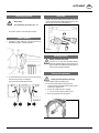
Parking the implement
Always park the implement securely!
- secure against rolling and tipping over
- Do not rest on feeler wheel, use support foot.
1. Lower the machine with the tractor hydraulic system
and place on support foot.
2. Pull off drive shaft and rest on support.
• Do not rest drive shaft on safety chain!
3. Uncouple implement from lifting gear.
Attaching in general
Safety hints:
see supplement-A1 points 7.) 8a. - h.)
- Pinning the machine to the three point linkage.
Road Transport
• Travelling on open roads may only be carried out as
described in chapter "Transport position".
• Fix the hydraulic lower link (4) in such a way that the
machine cannot swing out sideways.
- Push in the support foot (5) and secure.

- 6 -
9600_GB-TRANSPORT_285
GB
TRANSPORT AND WORKING POSITION
Driving on public roads
• Observe the official regulations of your country.
• Travelling on open roads may only be carried out as
described in chapter „Transport position“.
Total width of implement in the work position: more
than 3m
Total width of implement in the transport position: see
Technical Data
Hydraulic lower link
• Fix the hydraulic lower link (U) in such a way that the
machine cannot swing out sideways.
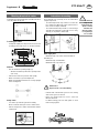
Conversion to working position
- Lower implement to ground.
- Mount all tine carriers onto rotor.
- Raise right and left guard (10) rail and secure with cotter
pin.
- Pull trap sheet out (X) and
secure with T-screw.
- Adjust gap (X) as
required.
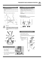
Conversion to transport position
- Lower implement to ground.
- Raise left and right guard rail (10) and secure with cotter
pin (6).
- Push trap sheet (9) right in and secure with T-screw
(K).
- Detach tine arms and put on (position 1).
Take note!
So that the rotor doesn’t turn by itself
when travelling, tine carriers (1a and 1b)
must remain fixed to rotor in the position
shown.
Position of running wheels
• The running wheels must be unlocked
during operation.
Secure in position 2.
• The running wheels should be locked
when moving the implement by hand.
Secure in position 1.
1a
1
TD31/95/10
1b
1

- 7 -
9500_GB-EINSATZ_285
GB
OPERATION
P.t.o. speed
- P.t.o. speed max. = 540 rpm
The most favourable p.t.o. rpm is
about 450 rpm.
- Should the forage be pulled back from
the swath into the raked strips (untidy operation), then
the p.t.o. rpm is to be reduced.
- Tractor's lower link (U) must be set so that there is no
sideways play in order to prevent tedder from swinging
back and forth.
- When working, the landwheels of the rotor assemblies
must be unlocked (Lever position 2).
- Put tractor control device (ST) into "free gear" (floating
position or "lower").
General guidelines for working with the
machine
Observe hints given in chapter “Front and rear
mounting”.
Safety hints:
see supplement-A1 points. 1.) 3.) 4.) 8i.)
• Do not work under the machine without safe
support.
• All work in the immediate area of the rotors may only
be carried out when the p.t.o. is switched off.
Caution!
Do not enter
rotor area
while driving
motor is
running.
- Choose the speed of travel so that all crops are picked
up thoroughly.
- In cases of overloading, shift down one gear.
- In order to obtain tidy raking operation, the rotor must
be as horizontal as possible. A very slight inclination
forward is allowed. This inclination is to be adjusted
using the upper link (7).
Setting the tine height “10 – 20 mm”
- Tines should lightly touch the ground. An adjustment
that is to deep will dirty the forage or damage the
turf.
• Carry out adjustment on firm even ground
1. Raise the implement using the tractor's lifting
gear.
2. Support machine
securely.
3. Loosen screw (8)
4. Adjust both wheels
accordingly then
retighten using screw
(8).
TD8/95/6a
495.173

- 8 -
1300-GB FRONT UND HECKANBAU (285)
GB
FRONT AND REAR MOUNTING
Mounting to the Reform METRAC
• Instead of the above mentioned mounting kits (4, 4a), use
the “Counterweight for front lifting gear” subassembly.
- Please observe the manufacturer’s advice when using
this subassembly
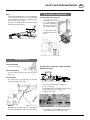
Preparing the front mounted – forward travelling
implement for work:
Note
Use a step-down gear (2) for a power take-
off speed of 1000 r.p.m. (see next page).
1. Raise implement with tractor’s lifting gear.
2. Loosen screws (S2).
3. By turning lever (8) the curved path for the tine control
and carrying axle is turned 180° (pos. F).
4. Retighten screws (S2).
5. Lower implement to ground with tractor’s lifting gear
and mount trap sheet to swath deposit side.
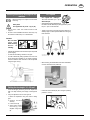
Mounting and working possibilities
Front mounting
The advantage of this working method is that the fodder
is not run over by the tractor. The swath is deposited to
the right in the direction of travel.
• In this type of operation a feeler wheel (5) is necessary
Upper link
- For implements equipped with a feeler wheel (5) a chain
upper link (6) is used through which the implement
adapts lengthwise to the ground independent of tractor
movement.
. As the tines are located so close to the feeler wheel
they can also optimally follow the uneven ground. The
result is very clean raking
Note:
If the bracket collides with the lower link
during normal mounting (holes 1 and 2), fit
the bracket to holes 2 and 3. Proceed in the
same manner if the bracket was originally
mounted at holes 4 and 5.
Mounting kit (4) and tension spring (4a)
The force the feeler wheel applies to the ground can
be improved by using both tension springs (4a). The
uneven ground can be followed more exactly.
The tension springs are fixed to the tractor with mounting
kits (4).
TD8/95/6a
KAT. II
6
TD 31/95/7a
4
4a
TD 31/95/5
5
Pos. FPos. H
1
25
36
4

- 9 -
1300-GB FRONT UND HECKANBAU (285)
FRONT AND REAR MOUNTING GB
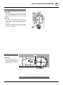
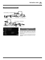
Additional gearing
For rear mounting
- use a reverse gear (1)
For front mounting
- use a step-down gear (2) for a power take-off speed of
1000 r.p.m.
Fitting the gear
The relevant gear is secured directly to the mounting
frame with an M12 safety nut (4)
Beware!
When fitting the gear always place the hexagonal bolts
(5) from the bearing fixture with head facing forward.
Preparing the rear mounted – forward travelling
implement for work:
1. Raise implement with tractor’s lifting gear.
2. Loosen screws (S2).
3. By turning lever (8) the curved path for the tine control
and carrying axle is turned 180° (pos. H).
4. Retighten screws (S2).
5. Lower implement to ground with tractor’s lifting gear
and mount trap sheet to swath deposit side.
TD 31/95/8
Pos. HPos. F
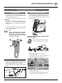
Rear mounting – forward travel
If a feeler wheel (5) is not used
• A rear mounted
ALPINTOP 300 U can
be operated without a
feeler wheel. A rigid upper
link (7) is necessary with
this operating method.
• The swath is deposited to
the right in the direction of
travel.
TD 31/95/15
7
Note
Front mounted ALPINTOP 300 U can be operated without
a feeler wheel (5). However this is not recommended
because without a feeler wheel, tine adaptation to the
ground would not be as optimal.
• Implements not equipped with a feeler wheel (5) must
travel with a rigid upper link (7).

- 10 -
1300-GB FRONT UND HECKANBAU (285)
FRONT AND REAR MOUNTING GB
TD 31/95/9a
0°
8°
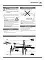
Lateral offset attachment
Advantage
Prevents swath from being run over.
• For this operating method the tractor
linkage drawbar is attached to the
implement in the “8°” position.
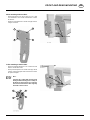
Using a feeler wheel with rear mounting
Feeler wheel
A feeler wheel (5) can be used with front mounting as
well as rear mounting. Only with rear mounting is a feeler
wheel attachment kit (5b) to be fitted to the mounting
frame.
Upper link
- For implements equipped with a feeler wheel (5) a chain
upper link (6) is used through which the implement
adapts lengthwise to the ground independent of tractor
movement.
As the tines are located so close to the feeler wheel
they can also optimally follow the uneven ground. The
result is very clean raking.
5
6

- 11 -
1300-GB FRONT UND HECKANBAU (285)
FRONT AND REAR MOUNTING GB
Offset mounting of the machine:
- Fit the left bracket, in the line of travel, to holes 1 and
2 to maintain the offset Fit the 2 flat washers outside
the bracket.
- Fit the perforated plate to the outside of the pipe elbows
using its own bolts.
In-line mounting of the machine:
- Fit the left and right bracket to holes 3 and 4. Fit a flat
washer outside the bracket.
- Fit the perforated plate to the outside of the pipe elbow
using its own bolts and put another flat washer outside
the perforated plate .
Note:
If the bracket collides with the lower link
during normal mounting (holes 1 and 2), fit
the bracket to holes 2 and 3. Proceed in the
same manner if the bracket was originally
mounted at holes 4 and 5. in each case one flat
washer
two flat washers outside
1
23
4
1
25
3
6
4

- 12 -
9600_GB-WARTUNG_285
GB
MAINTENANCE
Maintenance and servicing
Safety hints:
• see supplement-A1 points 1b.), 2.), 8i.),
9.)
• Do not work under the machine without
safe support.
In order to keep the implement in good condition after
long periods of ope ra ti on, please observe the following
points:
- After the first hours of operation, tighten
all screws.
In particular the tine connections and the
slewing headstock connections should
be checked.
- Always keep the stipulated air pressure in the tyres.
- Grease the lubrication points in accordance with the
regulation (see lubrication schedule).
Grease the lubrication nipples with universal grease
after every 20 hours of operation.
- Before leaving the machine over winter, oil all the joints
well and grease all bearings.
Drive shafts
- Lubricate the drive shafts every 8 hours of
operation.
- Pull sliding sections apart and grease well.
Cleaning of machine parts
Attention! Do not use high-pressure washers for the
cleaning of bearing- and hydraulic parts.
- Danger of rust!
- After cleaning, grease the machine according to the
lubrication chart and carry out a short test run.
- Cleaning with too high pressure may do damage to
varnish.
Winter storage
- Thoroughly clean machine before storage.
- Put up protection against weather.
- Protect exposed parts from rust.
- Lubricate all greasing points according to lubrication
chart.
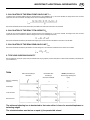
Lubrication chart
IV
20
h
1x 8x
1x
1x
2x
TD 31/95/18
20
h
IV
8h
FETT

9900-ZENTRAL_LEGENDE-SCHMIERPLAN - 13 -
Schmierplan
X
h alle X Betriebsstunden
40 F alle 40 Fuhren
80 F alle 80 Fuhren
1 J 1 x jährlich
100 ha alle 100 Hektar
FETT FETT
= Anzahl der Schmiernippel
= Anzahl der Schmiernippel
(IV) Siehe Anhang "Betriebsstoffe"
Liter Liter
* Variante
Siehe Anleitung des Herstellers
Smeerschema
X
h alle X bedrijfsuren
40 F alle 40 wagenladingen
80 F alle 80 wagenladingen
1 J 1 x jaarlijks
100 ha alle 100 hectaren
FETT VET
= Aantal smeernippels
= Aantal smeernippels
(IV) Zie aanhangsel "Smeermiddelen"
Liter Liter
* Varianten
zie gebruiksaanwijzing van de fabrikant
Schema di lubrificazione
X
h ogni X ore di esercizio
40 F ogni 40 viaggi
80 F ogni 80 viaggi
1 J volta all'anno
100 ha ogni 100 ettari
FETT GRASSO
= Numero degli ingrassatori
= Numero degli ingrassatori
(IV) vedi capitolo “materiali di esercizio”
Liter litri
* variante
vedi istruzioni del fabbricante
Plan de graissage
X
h Toutes les X heures de service
40 F Tous les 40 voyages
80 F Tous les 80 voyages
1 J 1 fois par an
100 ha tous les 100 hectares
FETT GRAISSE
= Nombre de graisseurs
= Nombre de graisseurs
(IV) Voir annexe "Lubrifiants"
Liter Litre
* Variante
Voir le guide du constructeur
Lubrication chart
X
h after every X hours operation
40 F all 40 loads
80 F all 80 loads
1 J once a year
100 ha every 100 hectares
FETT GREASE
= Number of grease nipples
= Number of grease nipples
(IV) see supplement "Lubrificants"
Liter Litre
* Variation
See manufacturer’s instructions
FETT
Esquema de lubricación
X
h Cada X horas de servicio
40 F Cada 40 viajes
80 F Cada 80 viajes
1 J 1 vez al año
100 ha Cada 100 hectáreas
FETT LUBRICANTE
= Número de boquillas de engrase
= Número de boquillas de engrase
(IV) Véase anexo “Lubrificantes”
Liter Litros
* Variante
Véanse instrucciones del fabricante
Plano de lubrificação
X
h Em cada X horas de serviço
40 F Em cada 40 transportes
80 F Em cada 80 transportes
1 J 1x por ano
100 ha Em cada100 hectares
FETT Lubrificante
= Número dos bocais de lubrificação
= Número dos bocais de lubrificação
(IV) Ver anexo ”Lubrificantes"
Liter Litro
* Variante
Ver instruções do fabricante
I
P
NL
D GBF
E

- 14 -
1200-GB Tech. Daten_285
GB
TECHNICAL DATA
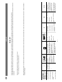
1 Only applies to basic implements
Defined use of the Rotary Swather
The "ALPINTOP 300 U (Type SK 285)" Rotary Swather is intended solely for normal use in agricultural work.
• The swathing of forage, silage fodder and straw.
Any other uses are regarded as not included in this definition.
The manufacturer takes no responsibility henceforth for any resulting damage which may occur. The user carries
sole risk.
• The keeping of operating, service and maintenance requirements layed down by the manufacturer also come under
the heading of „defined use“.
Technical Data
ALPINTOP 300 U Type SK 285
Number of rotors 1
Number of tine arms 8
Number of double tines per tine arm 3
Working width bis 3 m
Machine width in working position (without trap sheet) 2,5 m
Transport width - folded up 1,3 m
Working length12,7 m
Transport length12,7 m
Maximum height 1,6 m
Required power ab 12 kW (17 PS)
Weight1 without drive shaft 250 kg
P.t.o. speed1 max. 450 U/min
P.t.o. speed with step-down gear* max. 1000 U/min
Torque limiter 450 Nm (45 kpm)
Tyres (Running gear) 16x6,5-8
Tyres (Feeler wheel) 15x6-6
Tyre pressure 1 - 1,5 bar
Permanent Sound Emmission Level <70 dB(A)
* Optional equipment
All data subject to alteratio

- 15 -
1200-GB Tech. Daten_285
TECHNICAL DATA GB
Mounting and working possibilities
TD 31/95/3
Front mounting – forward travel
TD 31/95/4
Rear mounting – forward travel
Position of Vehicle Identification
Plate
The chassis number is engraved on the name plate
illustrated on the left. Warranty claims, enquiries and
spare parts orders cannot be made without quoting the
chassis number.
Please enter the number on the title page of the Operating
Instructions immediately on taking delivery of the vehicle/
equipment.

- 16 -
1200-GB Tech. Daten_285
TECHNICAL DATA GB
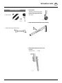
• Warning table
• Cardan shaft long (for AEBI tractors)
• Feeler wheel
Suitable for use with front mounting and
rear mounting (only in combination with
the feeler wheel attachment kit which
goes with it).
• Feeler wheel attachment kit for front mounting
• Feeler wheel attachment kit for rear
mounting
chassis number + …. 02179
Optional equipment
TD47/94/14

- 17 -
1200-GB Tech. Daten_285
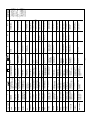
TECHNICAL DATA GB
FRONTANBAU -
ZAPFWELLENDREHZAHL = 540 U/min
M10 x 20
DIN 933
25,2 / 40 x 3
M8 x 12
8,5 / 18 x 2
RECHTSDREHEND
RECHTSDREHEND (standard)
RECHTSDREHEND
LINKSDREHEND
LINKSDREHEND
Z=16
Z=16
Z=28
Z=32
Z=28 Z=32
Z=16
Z=28
Z=32
FRONTANBAU -
ZAPFWELLENDREHZAHL = 1000 U/min
FRONTANBAU -
ZAPFWELLENDREHZAHL = 1000 U/min
HECKANBAU -
ZAPFWELLENDREHZAHL = 540 U/min
KEIN GETRIEBE!
FRONTANBAU -
ZAPFWELLENDREHZAHL = 540 U/min
11 / 34 x 3
TD 075-12-11
540 r.p.m. / 1000 r.p.m. (chassis number
+ … 02179)
• Reverse gear for rear mounting
• Reverse gear for front mounting
• Step-down gear for front mounting
Maintenance
0.15 kg of grease (IV)

GB-Anhang Titelblatt _BA-Allgemein
GB
SUPPLEMENT

GB-Anhang Titelblatt _BA-Allgemein
GB
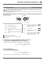
The decision must be made, ”original” or ”imitation”? The decision is often governed
by price and a ”cheap buy” can sometimes be very expensive.
Be sure you purchase the ”Original” with the cloverleaf sym-
bol!
• Quality and precise fitting
- Operating safety.
• Reliable operation
• Longer lasting
- Economy
• Guaranteed availability through your
Pöttinger Sales Service.
Things will run better with
genuine Pöttinger parts
The original cannot be copied ...

- 20 -
1200_GB-ANHANGA_SICHERHEIT
SUPPLEMENT - A GB
Recommendations for work safety
Recommendations for work safety
All points refering to safety in this manual are
in di ca ted by this sign.
1. Operating instructions
a. The operating instructions are important for the correct
operation of the machine. Make sure that the operating
instructions are always on hand when operating the
machine.
b. Keep the operating instructions as long as the machine
is in your hands.
c. Pass the operating instructions on to the buyer when
selling the machine.
d. Make sure that all safety and warning symbols remain
attached on the machine and keep them readable. The
hazard warnings provide important information for a
safe operation and, thus, your safety.
2. Qualified personnel
a. Only persons of legal age, mentally and physically able
and having been trained or familiarized accordingly must
operate this machine.
b. Persons not yet trained or familiarized or under training
must only operate this machine under the supervision
of an experienced person.
c. Inspection, setting and repair work must only be
performed by authorized persons.
3. Repair work
a. These instructions only refer to service, maintenance
and repair operations the user is able to carry out
without assistance. Any work beyond this scope has
to be carried out at authorized workshops only.
b. Repairs on the electrical and hydraulic system, preloaded
springs, pressure accumulators, etc. require sufficient
knowledge, correct tools and protective clothing and,
thus, must only be performed at authorized workshops.
4.) Defined use
a. See "Technical Data".
b. The keeping of operating, service and maintenance
re qui re ments layed down by the manufacturer also
come under the heading of "defined use".
5.) Spare parts
a. The original com po nents and ac ces so ries have been
de sig ned especially for these machines and appliances.
b. We want to make it quite clear that com po nents and
accesories that have not been sup plied by us have not
been tested by us.
c. The installation and/or use of such pro ducts can,
therefore, negatively chan ge or influence the
con struc tion characteristics of the appliance. We are not
liable for damages caused by the use of components
and accessories that have not been supplied by us.
d. Alterations and the use of auxiliary parts that are not
per mit ted by the manufacturer render all liability invalid.
6.) Protection devices
a. All protection devices must remain on the machine and
be maintained in proper con di tion. Punctual replacement
of worn and damaged covers is essential.
7.) Before starting work
a. Before commencing work, the operator must be aware
of all operating devices and functions. The learning
of these is too late after ha ving already commenced
operation!
b. The vehicle is to be tested for traffic and operating sa fe ty
before each operation.
8.) Asbestos
a. Certain sub-supplied com po nents
of the vehicle may contain asbestos
due to technical reasons. Ob ser ve
the warning on spare parts.
La pagina si sta caricando...
La pagina si sta caricando...
La pagina si sta caricando...
La pagina si sta caricando...
La pagina si sta caricando...
La pagina si sta caricando...
La pagina si sta caricando...
La pagina si sta caricando...
La pagina si sta caricando...
La pagina si sta caricando...
-
 1
1
-
 2
2
-
 3
3
-
 4
4
-
 5
5
-
 6
6
-
 7
7
-
 8
8
-
 9
9
-
 10
10
-
 11
11
-
 12
12
-
 13
13
-
 14
14
-
 15
15
-
 16
16
-
 17
17
-
 18
18
-
 19
19
-
 20
20
-
 21
21
-
 22
22
-
 23
23
-
 24
24
-
 25
25
-
 26
26
-
 27
27
-
 28
28
-
 29
29
-
 30
30


Pottinger TOP 300 U Istruzioni per l'uso
- Tipo
- Istruzioni per l'uso
- Questo manuale è adatto anche per
in altre lingue
Documenti correlati
-
Pottinger EUROTOP 280 Istruzioni per l'uso
-
-
-
-
-
-
-
-
-