CHAUVET DJ Vivid Drive 23N Guida di riferimento
- Tipo
- Guida di riferimento

Quick Reference Guide

1
EN
QUICK REFERENCE GUIDE
Vivid Drive 23N QRG Rev. 2
About This Guide
The Vivid Drive 23N Quick Reference Guide (QRG) has basic product information such as mounting and menu options.
Download the User Manual from www.chauvetdj.com
for more details.
Disclaimer
The information and specifications contained in this QRG are subject to change without notice.
Safety Notes
These Safety Notes include important information about installation, use, and maintenance.
Contact
Outside the U.S., United Kingdom, Ireland, Benelux, France, Germany, or Mexico, contact your distributor to request
support or return a product. Visit www.chauvetdj.com for contact information.
What is Included
• Vivid Drive 23N
• Power Cord
• Rack Mount Adapter
• DVI-to-DVI Jumper
• USB Cable
• Warranty Card
• Quick Reference Guide
To Begin
Unpack your Vivid Drive 23N and make sure you have received all parts in good condition. If the box or contents appear
damaged, notify the carrier immediately, not Chauvet.
AC Power
This product has an auto-ranging power supply that works with an input voltage range of 100 to 240 VAC, 50/60 Hz.
• ONLY connect this product to a grounded and protected circuit.
• DISCONNECT from power before cleaning.
• Make sure the power cord is not crimped or damaged.
• Never disconnect this product from power by pulling on the cord.
• DO NOT allow flammable materials close to the product when it is operating.
• DO NOT touch the product’s housing when it is on because it will be hot.
• The voltage of the outlet to which you are connecting this product must be within the range stated
on the decal or rear panel of the product.
• This product is for indoor use only! (IP20) To prevent risk of fire or shock, do not expose this
product to rain or moisture.
• Always mount this product in a location with adequate ventilation, at least 20 in (50 cm) from
adjacent surfaces.
• Be sure that no ventilation slots on the unit’s housing are blocked.
• Never connect this product to a dimmer or rheostat.
• Never carry the product by the power cord.
• The maximum ambient temperature is 104 °F (40 °C). Do not operate this product at higher
temperatures.
• In the event of a serious operating problem, stop using immediately.
• DO NOT open this product. It contains no user-serviceable parts.
• To eliminate unnecessary wear and improve its lifespan, during periods of non-use completely
disconnect the product from power via breaker or by unplugging it.
To eliminate wear and improve its lifespan, during periods of non-use completely disconnect the
product from power via breaker or by unplugging it.

EN
2
Vivid Drive 23N QRG Rev. 2
QUICK REFERENCE GUIDE
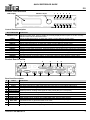
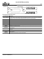
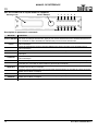
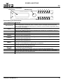
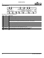
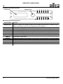
Product Front Overview
Control Panel Description
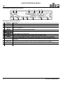
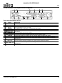
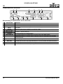
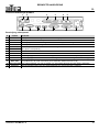
Product Rear Overview
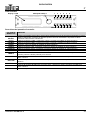
Rear Panel Description
BUTTON/KNOB FUNCTION
SELECT Knob
Rotate to navigate upwards or downwards through the menu list, and increase or decrease a
selected numeric value. Push to enable the currently displayed menu option or set the currently
selected value into the selected function.
<CV/1> Selects CVBS input source, or enters the number 1 when editing a number value
<HDMI/2> Selects HDMI input source, or enters the number 2 when editing a number value
<SDI/3> Enters the number 3 when editing a number value
<VGA/4> Selects VGA input source, or enters the number 4 when editing a number value
<YPbPr/5> Selects YPbPr input source, or enters the number 5 when editing a number value
<BLACK/6> Blacks out the video output, or enters the number 6 when editing a number value
<MENU> Exits the current menu or function. Press and hold for 3 seconds to lock or unlock the control panel.
<SCALE/7> Navigates directly to the Scale menu, or enters the number 7 when editing a number value
<SPLIT/8> Navigates directly to the Split menu, or enters the number 8 when editing a number value
<COM/9> Enters the number 9 when editing a number value
<SAVE/0> Navigates directly to the Save menu, or enters the number 0 when editing a number value
<LOAD/10+> Navigates directly to the Load menu
# PORT FUNCTION
1RS232RJ12 port for remote control system connection.
2 USB B 1 USB B port for firmware updates
3 DVI In DVI input connector for video signal from DVI1 OUT (11) or a pre-scaled video source
4 USB B 2 USB B port for connecting to NovaLCT Mars
5 Ethernet Out 2
Ethernet ports for sending video signal to video panels (6 is port 1, 5 is port 2)
6 Ethernet Out 1
7CVBS INBNC connector for CVBS input
8 VGA/YPbPr IN DE-15 connector for video input from a VGA or YPbPr source
9 HDMI IN HDMI input port to scaler. This port must be used to use the scaler.
10 HDMI LOOP HDMI output port for sending non-scaled HDMI video signal to other devices
11 DVI1 OUT
DVI output connector for sending scaled video signal to the DVI In port (3). This port must be
connected to DVI In (3) for the scaler to be used.
12 DVI2+VGA OUT DVI output connector for sending scaled video signal to other devices
13 Power In Power input socket for a voltage range of 100 to 240 VAC, 50/60 Hz
LCD Display
SELECT Knob
1
MENU
10+
23456
7890
12 3 4 56
1178 910 1312

3
EN
QUICK REFERENCE GUIDE
Vivid Drive 23N QRG Rev. 2
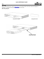
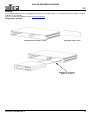
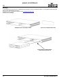
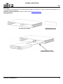
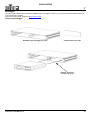
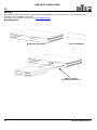
Mounting
Before mounting this product, read the Safety Notes. The Vivid Drive 23N comes with a Rack Mount Adapter for
mounting 1 or 2 Vivid Drive 23N products in a standard 19-inch rack.
Mounting Diagram
Insert into slot and
secure with screws
Rack Mount Adapter Empty Slot Cover

EN
4
Vivid Drive 23N QRG Rev. 2
QUICK REFERENCE GUIDE
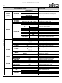
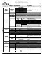
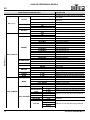
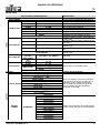
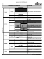
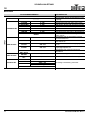
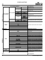
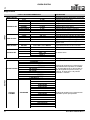
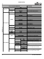
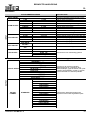
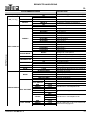
Menu Map
PROGRAMMING LEVELS DESCRIPTION
INPUT INPUT Main Level
INPUT
INPUT DETAIL _ _ _ _ _ Displays the currently selected input
ZOOM ADJUST
V UP 0–768 Stretches the video upwards
V DOWN 0–768 Stretches the video downwards
V UP/DOWN 0–384 Stretches the video up and down
H LEFT 0–1024 Stretches the video leftwards
H RIGHT 0–1024 Stretches the video rightwards
H LEFT/RIGHT 0–512 Stretches the video left and right
CENTER 0–384 Stretches the video in all directions
RESET Resets all Zoom Adjust settings
VGA ADJUST
H POS -100–100 Adjusts horizontal position of VGA video
V POS -100–100 Adjusts vertical position of VGA video
CLOCK -100–100 Adjusts the VGA input signal clock
PHASE -100–100 Adjusts the VGA input signal phase
AUTO ADJUST Automatically adjusts VGA input signal
ADC ADJUST
ADC AUTO
ADJUST
YES <SEL>, NO <MENU> Automatically adjusts the brightness
ADC RESET
ALL
YES <SEL>, NO <MENU> Resets the ADC setting
SDI ADJUST
H POS 27–227
Reserved for future use
V POS 27–227
ANTI-ALIAS
STEP_126
STEP_7
RESET
OUTPUT OUTPUT Main Level
OUTPUT
OUTPUT
DETAIL
_ _ _ _x_ _ _ _x_ _
Displays currently set output resolution and
frequency, DVI mode, bit depth, data range,
DE (VGA or YPbPr) signal status, position,
and size, and the horizontal and vertical
polarity.
DVI MODE: _ _ _
BIT DEPTH: _ _ BIT
DATA RANGE: _ _ _ _ _
DE: _ _ _
DE H POS: _ _ _ _ _
DE V POS: _ _ _ _ _
DE H SIZE: _ _ _ _ _
DE V SIZE: _ _ _ _ _
H POLARITY: _ _ _
V POLARITY: _ _ _
OUTPUT
FORMAT
STANDARD
800x600x60
Selects output resolution and frequency
from preset options
1024x768x60
1024x768x75
1280x720x60
1280x720x50
1280x768x60
1280x800x60
1280x1024x60
1360x768x60
1366x768x60
1400x1050x60
1440x800x60
1440x900x60
1600x1200x60
1680x1050x60
1920x1080x60

5
EN
QUICK REFERENCE GUIDE
Vivid Drive 23N QRG Rev. 2
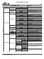
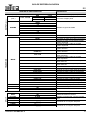
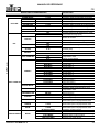
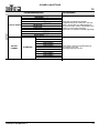
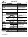
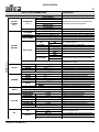
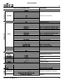
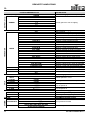
OUTPUT (cont.) OUTPUT Main Level (cont.)
OUTPUT (cont.)
OUTPUT
FORMAT
(cont.)
STANDARD
(cont.)
1920x1080x50
Selects output resolution and frequency
from preset options
1920x1120x60
1920x1200x60
2048x1152x60
2560x812x60
1560x816x60
CUSTOM
_ _ _ _x_ _ _ _x_ _
Sets custom resolution and frequency
OUTPUT
ADJUST
DVI MODE
DVI Sets the protocol to DVI (default)
HDMI Sets the protocol to HDMI
BIT DEPTH 8 BIT (DVI) / 8–12 BIT (HDMI) Sets bit depth in HDMI mode
DATA RANGE
IMAGE RGB color space
VIDEO YUV color space
DE ADJUST
DE
OFF
Enables or disables adjusting the signal
from the DE-15 connector
ON
H POS 0–_ _ _ _ _ Adjusts the horizontal position
V POS 0–_ _ _ _ _ Adjusts the vertical position
H SIZE 61–_ _ _ _ Adjusts the horizontal size (width)
V SIZE 61–_ _ _ _ Adjusts the vertical size (height)
H POLARITY
POS
Sets the phase of the horizontal scan
NEG
V POLARITY
POS
Sets the phase of the vertical scan
NEG
RESET Resets all output adjust settings
SCALE
H SIZE 61–_ _ _ _ Sets the width of DVI1 OUT
V SIZE 61–_ _ _ _ Sets the height of DVI1 OUT
H POS -100–_ _ _ _ Sets the horizontal position of DVI1 OUT
V POS -16–_ _ _ _ Sets the vertical position of DVI1 OUT
RESET Resets scale settings
SCREEN
H SIZE 61–_ _ _ _ Sets the width of DVI2+VGA OUT
V SIZE 61–_ _ _ _ Sets the Height of DVI2+VGA OUT
H POS 0–_ _ _ _
Sets the horizontal position of DVI2+VGA
OUT
V POS 0–_ _ _ _ Sets the vertical position of DVI2+VGA OUT
MODE
FULL SIZE DVI2+VGA OUT outputs unscaled video
SCREEN SIZE DVI2+VGA OUT outputs scaled video
RESET Resets screen settings
RATIO
4:3 Sets the aspect ratio to 4:3
16:9 Sets the aspect ration to 16:9
NORMAL Does not alter the aspect ratio
PICTURE
BRIGHTNESS 0–100 Adjusts the brightness of the output
CONTRAST 0–100 Adjusts the contrast of the output
SATURATION 0–100 Adjusts the saturation of the output
SHARPNESS 0–100 Adjusts the sharpness of the output
COLOR RED 0–100 Adjusts the overall red level
COLOR GRN 0–100 Adjusts the overall green level
COLOR BLUE 0–100 Adjusts the overall blue level
RESET Resets all picture settings
PIP
PIP
OFF
Enables or disables PIP
ON
LAYOUT
PIP L+T PIP appears at top left of output
PBP L+R Output is split vertically (left and right)
PBP T+B Output is split horizontally (top and bottom)
PROGRAMMING LEVELS DESCRIPTION

EN
6
Vivid Drive 23N QRG Rev. 2
QUICK REFERENCE GUIDE
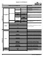
OUTPUT (cont.) OUTPUT Main Level (cont.)
OUTPUT (cont.)
PIP (cont.)
SWAP IMAGE
OFF
Switches Image A with Image B
ON
ALPHA 0–16 Sets transparency of PIP
SELECT
IMAGE A Enables scaling of Image A
IMAGE B Enables scaling of Image B
TEXT OVERLAY
TEXT OVERLAY
OFF
Enables or disables overlay
ON
PRESET
User Custom color
WhOnBk1 White on black 1
WhOnBk2 White on black 2
BkOnWh1 Black on white 1
BkOnWh2 Black on white 2
GrnOnBk1 Green on black 1
GrnOnBk2 Green on black 2
GrnOnWh1 Green on white 1
GrnOnWh2 Green on white 2
RedOnBk1 Red on black 1
RedOnBk2 Red on black 2
RedOnWh1 Red on white 1
RedOnWh2 Red on white 2
BLEND MODE
MODE1 Overlay is solid, background is transparent
MODE2 Overlay is transparent, no background
BLEND LEVEL 0–15 Sets overlay transparency
ABOVE/BELOW
BELOW Below mode
ABOVE Above mode
AND/OR
OR Or mode (left)
AND And mode (right)
RED 0–248 Sets custom red level of overlay
GREEN 0–252 Sets custom green level of overlay
BLUE 0–248 Sets custom blue level of overlay
DISPLAY MODE
MODE
BLACK SCREEN Blacks out the output
LIVE IMAGE Video output
FREEZE IMAGE Freezes the output on a single frame
FLAT IMAGE Displays a single color
TEST PATTERN Displays a test pattern
TEST PATTERN
TEST PATTERN 1–66 Selects from 66 available test patterns
AUTO SWITCH
OFF Test patterns will not switch automatically
1–10s Sets the interval between test patterns
RED 0–255
Sets the color of test pattern 65GREEN 0–255
BLUE 0–255
HOR STEP 0–64
Sets the number of steps in test pattern 66
VER STEP 0–64
COLOR
RED
Sets the color of test pattern 66
GREEN
BLUE
WHITE
FLAT COLOR
RED 0–255
Sets the single color to be displayed in Flat
Image mode
GREEN 0–255
BLUE 0–255
PROGRAMMING LEVELS DESCRIPTION

7
EN
QUICK REFERENCE GUIDE
Vivid Drive 23N QRG Rev. 2
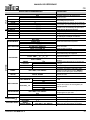
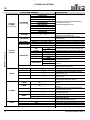
OUTPUT (cont.) OUTPUT Main Level (cont.)
OUTPUT (cont.)
GAMMA
LINEAR
Sets the gamma of the output
sRGB
-1.2
1.2
-1.4
1.4
-1.6
1.6
TRANSITION TRANSITION Main Level
TRANSITION
MODE
CUT No transition
FADE Video sources fade with transitioning
POP L+T Video source 2 enters from top left
PUSH L+T Video source 1 exits at top left
POP R+T Video source 2 enters from top right
PUSH R+T Video source 1 exits at top right
POP L+B Video source 2 enters from bottom left
PUSH L+B Video source 1 exits at bottom left
POP R+B Video source 2 enters from bottom right
PUSH R+B Video source 1 exits at bottom right
POP CENT Video source 2 expands from the center
PUSH CENT Video source 1 shrinks into the center
POP LEFT Video source 2 enters from the left
PUSH LEFT Video source 1 exits to the left
POP RIGHT Video source 2 enters from the right
PUSH RIGHT Video source 1 exits to the right
POP TOP Video source 2 enters from the top
PUSH TOP Video source 1 exits to the top
POP BOTTOM Video source 2 enters from the bottom
PUSH BOTTOM Video source 1 exits to the bottom
FADE TIME 0.0–1.0s Sets time a transition takes
ALPHA 0–16 Sets transparency
DEINTERLACE
ON
Enables or disables deinterlacing
OFF
SPLIT SPLIT Main Level
SPLIT
SPLIT
OFF
Enable/Disable Split
ON
H TOTAL 0–4096
Sets the size of the total panel assembly
V TOTAL 0–4096
H POS 0–_ _ _ _
Sets the position of this driver’s output on
the panel assembly
V POS 0–_ _ _ _
H SIZE 0–_ _ _ _
Sets the size of this driver’s output on the
panel assembly
V SIZE 0–_ _ _ _
SAVE SETUP SAVE SETUP Main Level
SAVE TO SAVE 1–10 Saves the current settings
LOAD FROM SAVE 1–10 Loads the desired saved settings
DELAY CALL 0–255s Sets output delay for multi-driver chains
SYSTEM SYSTEM Main Level
SYSTEM
SYSTEM INFO
MCU VER: _._ _
Displays system informationVIDEO VER: _._ _
SN: _ _ _ _
TECH
SUPPORT
SALES HOTLINE: (800) 762-1084
Displays phone numbers for assistance
AFTER-SALE SERVICE:
PROGRAMMING LEVELS DESCRIPTION

EN
8
Vivid Drive 23N QRG Rev. 2
QUICK REFERENCE GUIDE
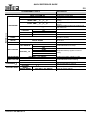
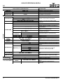
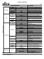
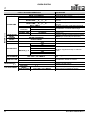
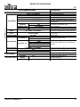
SYSTEM (cont.) SYSTEM Main Level (cont.)
SYSTEM (cont.)
DATE&TIME
DATE: YYYY-MM-DD Displays the current date
TIME: HH:MM:SS Displays the current time
WORK TIME: _ _d:_ _h:_ _m
Displays how long the product has been
running
TOTAL TIME: _ _d:_ _h:_ _m
Displays the total time for which the product
has run
BOOT TIMES: _ _
Displays number of times the product has
been turned on
TIMING
CONTROL
ON
Enables/Disables clock control
OFF
CHANGE DATE YYYY-MM-DD Sets the date
CHANGE TIME HH:MM:SS Sets the time
LOCK FRONT
PANEL
YES <SEL>, NO <MENU>
Locks the front panel (hold <MENU> for 3
seconds to unlock)
LICENSE
SETUP
ENTER PASSWORD
000000–999999
No function
CAN USE TIME NO LIMIT No function
HOT BACKUP
HOT BACKUP
OFF
Enables/Disables hot backup
ON
BACKUP_1–5
CV1
Designates backup signals in order of
priority
HDMI
YPbPr
VGA
SDI
USB UPGRADE YES <SEL>, NO <MENU> Enables a firmware update by USB
EDID FOLLOW
OFF
Enables/Disables EDID following
ON
LANGUAGE
ENG Sets the language to English
Sets the language to Chinese
FACTORY RESET
FACTORY
RESET
YES <SEL>, NO <MENU> Resets the product to factory settings
SAVE IP RESET YES <SEL>, NO <MENU> Clears all saved settings
PROGRAMMING LEVELS DESCRIPTION

9
ES
GUÍA DE REFERENCIA RÁPIDA
Vivid Drive 23N GRR Rev. 2
Acerca de esta guía
La Guía de referencia rápida (GRR) del Vivid Drive 23N contiene información básica sobre el producto, como montaje y
opciones de menú. Descargue el manual de usuario de www.chauvetdj.com
para una información más detallada.
Exención de responsabilidad
La información y especificaciones contenidas en esta GRR están sujetas a cambio sin previo aviso.
Notas de seguridad
Estas notas de seguridad incluyen información importante sobre el montaje, uso y mantenimiento.
Contacto
Fuera de EE. UU., Reino Unido, Irlanda, Benelux, Francia, Alemania o México póngase en contacto con su distribuidor
para solicitar asistencia o devolver un producto. Visite www.chauvetdj.com para información de contacto.
Qué va incluido
• Vivid Drive 23N
• Cable de alimentación
• Adaptador de montaje en rack
• Puente DVI a DVI
•Cable USB
• Tarjeta de garantía
• Guía de referencia rápida
Para empezar
Desembale su Vivid Drive 23N y asegúrese de que ha recibido todas las partes en buen estado. Si la caja o los
componentes parecen dañados, notifíqueselo inmediatamente al transportista, no a Chauvet.
Corriente alterna
Este producto tiene una fuente de alimentación con detección automática que puede funcionar con un rango de tensión
de entrada de 100–240 VCA, 50/60 Hz.
• Conecte este producto SOLO a un circuito con toma de tierra y protegido.
• Desconecte siempre de la alimentación antes de la limpieza.
• Asegúrese de que el cable de alimentación no está retorcido ni estropeado.
• Nunca desconecte este producto de la alimentación tirando del cable.
• NO permita la presencia de materiales inflamables cerca de la unidad cuando esté en
funcionamiento.
• NO toque este producto cuando esté en funcionamiento, pues podría estar caliente.
• La tensión del enchufe al que conecte este producto ha de estar en el rango establecido en el
grabado o en el panel posterior del producto.
• ¡Este producto es para uso en interiores solamente! (IP20) Para evitar riesgos de incendio o
descarga, no exponga este producto a la lluvia o la humedad.
• Monte siempre este producto en una ubicación con ventilación adecuada, al menos a 20 in (50
cm) de superficies adyacentes.
• Asegúrese de que ninguna ranura de ventilación en la carcasa de la unidad queda bloqueada.
• Nunca conecte este producto a un atenuador o reostato.
• Nunca transporte el producto por el cable de alimentación.
• La temperatura ambiente máxima es de 104 °F (40 °C). No haga funcionar este producto a
temperaturas más altas.
• En caso de un problema grave de funcionamiento, deje de usarlo inmediatamente.
• NO abra este producto. No contiene piezas reparables por el usuario.
• Para evitar un desgaste innecesario y alargar su vida útil, desconecte completamente el producto
mediante el interruptor o desenchufándolo durante periodos en que no se use.
Para evitar un desgaste innecesario y alargar su vida útil, desconecte completamente el producto
mediante el interruptor o desenchufándolo durante periodos en que no se use.

ES
10
Vivid Drive 23N GRR Rev. 2
GUÍA DE REFERENCIA RÁPIDA
Vista general frontal del producto
Descripción del panel de control
BOTÓN/MANDO FUNCIÓN
Mando SELECT
Gire para desplazarse hacia adelante o hacia atrás por la lista del menú, y aumente o disminuya
un valor numérico seleccionado. Pulse para habilitar la opción de menú actualmente visualizada o
configurar el valor seleccionado actualmente dentro de la función seleccionada.
<CV/1> Selecciona la fuente de entrada CVBS o introduce el número 1 cuando se edita un valor numérico
<HDMI/2> Selecciona la fuente de entrada HDMI o introduce el número 2 cuando se edita un valor numérico
<SDI/3> Introduce el número 3 cuando se edita un valor numérico
<VGA/4> Selecciona la fuente de entrada VGA o introduce el número 4 cuando se edita un valor numérico
<YPbPr/5> Selecciona la fuente de entrada YPbPr o introduce el número 5 cuando se edita un valor numérico
<BLACK/6> Apaga la salida de vídeo o introduce el número 6 cuando se edita un valor numérico
<MENU>
Sale del menú o función actual. Mantenga pulsado durante 3 segundos para bloquear o
desbloquear el panel de control.
<SCALE/7>
Se desplaza directamente al menú Scale (Escala) o introduce el número 7 cuando se edita un
valor numérico
<SPLIT/8>
Se desplaza directamente al menú Split (Dividir) o introduce el número 8 cuando se edita un valor
numérico
<COM/9> Introduce el número 9 cuando se edita un valor numérico
<SAVE/0>
Se desplaza directamente al menú Save (Guardar) o introduce el número 0 cuando se edita un
valor numérico
<LOAD/10+> Se desplaza directamente al menú Load (Cargar)
Pantalla LCD
Mando SELECT
1
MENU
10+
23456
7890

11
ES
GUÍA DE REFERENCIA RÁPIDA
Vivid Drive 23N GRR Rev. 2
Vista general trasera del producto
Descripción del panel posterior
# PUERTO FUNCIÓN
1RS232Puerto RJ12 para la conexión del sistema de control remoto.
2 USB B 1 Puerto USB B para actualizaciones de firmware
3 DVI In
Conector de entrada DVI para la señal de vídeo desde DVI1 OUT (11) o una fuente de vídeo con la
escala ya modificada
4 USB B 2 Puerto USB B para conexión a NovaLCT Mars
5 Ethernet Out 2
Puertos Ethernet para enviar señal de vídeo a los paneles de vídeo (6 es puerto 1, 5 es puerto 2)
6 Ethernet Out 1
7CVBS INConector BNC para entrada CVBS
8 VGA/YPbPr IN Conector DE-15 para entrada de vídeo desde una fuente VGA o YPbPr
9 HDMI IN Puerto de entrada HDMI a escalador. Se debe utilizar este puerto para usar el escalador.
10 HDMI LOOP
Puerto de entrada HDMI para enviar señal de vídeo HDMI sin la escala modificada a otros
dispositivos
11 DVI1 OUT
Conector de salida DVI para enviar señal de vídeo con la escala modificada al puerto DVI de
entrada (3). Este puerto se debe conectar a DVI In (3) para poder usar el escalador.
12 DVI2+VGA OUT Puerto de entrada DVI para enviar señal de vídeo con la escala modificada a otros dispositivos
13 Power In Conector de entrada de alimentación para un rango de tensión de 100 a 250 V CA, 50/60 Hz
12 3 4 56
1178 910 1312

ES
12
Vivid Drive 23N GRR Rev. 2
GUÍA DE REFERENCIA RÁPIDA
Montaje
El Vivid Drive 23N viene con un adaptador de montaje en rack para montar 1 o 2 productos Vivid Drive 23N en un rack
estándar de 19 pulgadas.
Antes de montar este producto, lea las Notas de seguridad
.
Diagrama de montaje
Insértela en la ranura y
fíjela con tornillos
Adaptador de montaje en rack Tapa para ranura vacía

13
ES
GUÍA DE REFERENCIA RÁPIDA
Vivid Drive 23N GRR Rev. 2
Mapa de menú
NIVELES DE PROGRAMACIÓN DESCRIPCIÓN
INPUT INPUT Nivel Principal
INPUT
INPUT DETAIL _ _ _ _ _
Muestra la entrada actualmente seleccionada
ZOOM ADJUST
V UP 0–768 Expande la imagen hacia arriba
V DOWN 0–768 Expande la imagen hacia abajo
V UP/DOWN 0–384
Expande la imagen hacia arriba y hacia abajo
H LEFT 0–1024 Expande la imagen hacia la izquierda
H RIGHT 0–1024 Expande la imagen hacia la derecha
H LEFT/RIGHT 0–512 Expande la imagen a izquierda y derecha
CENTER 0–384
Expande la imagen en todas las direcciones
RESET
Restablece la configuración de los ajustes de zoom
VGA ADJUST
H POS -100–100 Ajusta la posición horizontal del vídeo VGA
V POS -100–100 Ajusta la posición vertical del vídeo VGA
CLOCK -100–100 Ajusta el reloj de la señal de entrada VGA
PHASE -100–100 Ajusta la fase de la señal de entrada VGA
AUTO ADJUST
Ajusta automáticamente la señal de entrada VGA
ADC ADJUST
ADC AUTO
ADJUST
YES <SEL>, NO <MENU> Ajusta automáticamente el brillo
ADC RESET
ALL
YES <SEL>, NO <MENU> Restablece la configuración del CAD
SDI ADJUST
H POS 27–227
Reservado para usos futuros
V POS 27–227
ANTI-ALIAS
STEP_126
STEP_7
RESET
OUTPUT OUTPUT Nivel Principal
OUTPUT
OUTPUT DETAIL
_ _ _ _x_ _ _ _x_ _
Muestra la resolución y frecuencia de salida
actualmente configuradas; modo DVI;
profundidad de bits; intervalo de datos;
estado, posición y tamaño de la señal DE
(VGA o YPbPr); y la polaridad vertical y
horizontal.
DVI MODE: _ _ _
BIT DEPTH: _ _ BIT
DATA RANGE: _ _ _ _ _
DE: _ _ _
DE H POS: _ _ _ _ _
DE V POS: _ _ _ _ _
DE H SIZE: _ _ _ _ _
DE V SIZE: _ _ _ _ _
H POLARITY: _ _ _
V POLARITY: _ _ _
OUTPUT
FORMAT
STANDARD
800x600x60
Selecciona la resolución y frecuencia de
salida a partir de las opciones
preestablecidas
1024x768x60
1024x768x75
1280x720x60
1280x720x50
1280x768x60
1280x800x60
1280x1024x60
1360x768x60
1366x768x60
1400x1050x60
1440x800x60
1440x900x60
1600x1200x60
1680x1050x60
1920x1080x60

ES
14
Vivid Drive 23N GRR Rev. 2
GUÍA DE REFERENCIA RÁPIDA
OUTPUT (cont.) OUTPUT Nivel Principal (cont.)
OUTPUT (cont.)
OUTPUT
FORMAT
(cont.)
STANDARD
(cont.)
1920x1080x50
Selecciona la resolución y frecuencia de
salida a partir de las opciones
preestablecidas
1920x1120x60
1920x1200x60
2048x1152x60
2560x812x60
1560x816x60
CUSTOM
_ _ _ _x_ _ _ _x_ _
Establece la resolución y frecuencia personalizadas
OUTPUT
ADJUST
DVI MODE
DVI
Establece el protocolo a DVI (predeterminado)
HDMI Establece el protocolo a HDMI
BIT DEPTH 8 BIT (DVI) / 8–12 BIT (HDMI)
Establece la profundidad de bits en el modo HDMI
DATA RANGE
IMAGE Espacio de color RGB
VIDEO Espacio de color YUV
DE ADJUST
DE
OFF
Habilita o deshabilita el ajuste de la señal
desde el conector DE-15
ON
H POS 0–_ _ _ _ _ Ajusta la posición horizontal
V POS 0–_ _ _ _ _ Ajusta la posición vertical
H SIZE 61–_ _ _ _ Ajusta el tamaño horizontal (anchura)
V SIZE 61–_ _ _ _ Ajusta el tamaño vertical (altura)
H POLARITY
POS
Establece la fase de exploración horizontal
NEG
V POLARITY
POS
Establece la fase de exploración vertical
NEG
RESET
Restablece todas las configuraciones de
ajuste de salida
SCALE
H SIZE 61–_ _ _ _ Establece la anchura de DVI1 OUT
V SIZE 61–_ _ _ _ Establece la altura de DVI1 OUT
H POS -100–_ _ _ _
Establece la posición horizontal de DVI1 OUT
V POS -16–_ _ _ _ Establece la posición vertical de DVI1 OUT
RESET Restablece la configuración de la escala
SCREEN
H SIZE 61–_ _ _ _ Establece la anchura de DVI2+VGA OUT
V SIZE 61–_ _ _ _ Establece la altura de DVI2+VGA OUT
H POS 0–_ _ _ _
Establece la posición horizontal de
DVI2+VGA
OUT
V POS 0–_ _ _ _
Establece la posición vertical de
DVI2+VGA
OUT
MODE
FULL SIZE
DVI2+VGA OUT
emite vídeo sin modificar la
escala
SCREEN SIZE
DVI2+VGA OUT
emite vídeo con la escala
modificada
RESET Restablece la configuración de la pantalla
RATIO
4:3 Establece la relación de aspecto a 4:3
16:9 Establece la relación de aspecto a 16:9
NORMAL No altera la relación de aspecto
PICTURE
BRIGHTNESS 0–100 Ajusta el brillo de la salida
CONTRAST 0–100 Ajusta el contraste de la salida
SATURATION 0–100 Ajusta la saturación de la salida
SHARPNESS 0–100 Ajusta la nitidez de la salida
COLOR RED 0–100 Ajusta el nivel de rojo general
COLOR GRN 0–100 Ajusta el nivel de verde general
COLOR BLUE 0–100 Ajusta el nivel de azul general
RESET Restablece todos los ajustes de imagen
PIP PIP
OFF
Habilita o deshabilita el PIP
ON
NIVELES DE PROGRAMACIÓN DESCRIPCIÓN

15
ES
GUÍA DE REFERENCIA RÁPIDA
Vivid Drive 23N GRR Rev. 2
OUTPUT (cont.) OUTPUT Nivel Principal (cont.)
OUTPUT (cont.)
PIP (cont.)
LAYOUT
PIP L+T
PIP aparece en la parte superior izquierda
de la salida
PBP L+R
La salida se divide verticalmente (izquierda
y derecha)
PBP T+B
La salida se divide horizontalmente (arriba y abajo)
SWAP IMAGE
OFF
Intercambia la imagen A con la imagen B
ON
ALPHA 0–16 Establece la transparencia del PIP
SELECT
IMAGE A Habilita el escalado de la imagen A
IMAGE B Habilita el escalado de la imagen B
TEXT OVERLAY
TEXT OVERLAY
OFF
Habilita o deshabilita la superposición
ON
PRESET
User Color personalizado
WhOnBk1 Blanco sobre negro 1
WhOnBk2 Blanco sobre negro 2
BkOnWh1 Negro sobre blanco 1
BkOnWh2 Negro sobre blanco 2
GrnOnBk1 Verde sobre negro 1
GrnOnBk2 Verde sobre negro 2
GrnOnWh1 Verde sobre blanco 1
GrnOnWh2 Verde sobre blanco 2
RedOnBk1 Rojo sobre negro 1
RedOnBk2 Rojo sobre negro 2
RedOnWh1 Rojo sobre blanco 1
RedOnWh2 Rojo sobre blanco 2
BLEND MODE
MODE1
La superposición es opaca, el fondo es transparente
MODE2 La superposición es transparente, sin fondo
BLEND LEVEL 0–15
Establece la transparencia de la superposición
ABOVE/BELOW
BELOW Bajo modo
ABOVE Sobre modo
AND/OR
OR OR modo (izquierda)
AND AND modo (derecho)
RED 0–248
Establece el nivel de rojo de la superposición
GREEN 0–252
Establece el nivel de verde de la superposición
BLUE 0–248
Establece el nivel de azul de la superposición
DISPLAY MODE
MODE
BLACK SCREEN Apaga la salida
LIVE IMAGE Salida de vídeo
FREEZE IMAGE Congela la salida en un solo fotograma
FLAT IMAGE Muestra un solo color
TEST PATTERN Muestra un patrón de prueba
TEST PATTERN
TEST PATTERN 1–66
Selecciona entre 66 patrones de prueba disponibles
AUTO SWITCH
OFF Los patrones no cambian automáticamente
1–10s
Establece el intervalo entre patrones de prueba
RED 0–255
Establece el color del patrón de prueba 65GREEN 0–255
BLUE 0–255
HOR STEP 0–64
Establece el número de pasos del patrón de
prueba 66
VER STEP 0–64
COLOR
RED
Establece el color del patrón de prueba 66
GREEN
BLUE
WHITE
NIVELES DE PROGRAMACIÓN DESCRIPCIÓN

ES
16
Vivid Drive 23N GRR Rev. 2
GUÍA DE REFERENCIA RÁPIDA
OUTPUT (cont.) OUTPUT Nivel Principal (cont.)
OUTPUT (cont.)
DISPLAY MODE
(cont.)
FLAT COLOR
RED 0–255
Establece el único color que se visualizará
en el modo Imagen plana
GREEN 0–255
BLUE 0–255
GAMMA
LINEAR
Establece la gama de salida
sRGB
-1.2
1.2
-1.4
1.4
-1.6
1.6
TRANSITION TRANSITION Nivel Principal
TRANSITION
MODE
CUT Sin transición
FADE
Las fuentes de vídeo hacen fade con transición
POP L+T
La fuente de vídeo 2 entra desde la parte
superior izquierda
PUSH L+T
La fuente de vídeo 1 sale por la parte
superior izquierda
POP R+T
La fuente de vídeo 2 entra desde la parte
superior derecha
PUSH R+T
La fuente de vídeo 1 sale por la parte
superior derecha
POP L+B
La fuente de vídeo 2 entra desde la parte
inferior izquierda
PUSH L+B
La fuente de vídeo 1 sale por la parte
inferior izquierda
POP R+B
La fuente de vídeo 2 entra desde la parte
inferior derecha
PUSH R+B
La fuente de vídeo 1 sale por la parte
inferior derecha
POP CENT
La fuente de vídeo 2 se expande desde el centro
PUSH CENT
La fuente de vídeo 1 se encoge hacia el centro
POP LEFT
La fuente de vídeo 2 entra desde la izquierda
PUSH LEFT La fuente de vídeo 1 sale por la izquierda
POP RIGHT
La fuente de vídeo 2 entra desde la derecha
PUSH RIGHT La fuente de vídeo 1 sale por la derecha
POP TOP La fuente de vídeo 2 entra desde arriba
PUSH TOP La fuente de vídeo 1 sale por arriba
POP BOTTOM La fuente de vídeo 2 entra desde abajo
PUSH BOTTOM La fuente de vídeo 1 sale por abajo
FADE TIME 0.0–1.0s
Establece el tiempo que tarda una transición
ALPHA 0–16 Establece la transparencia
DEINTERLACE
ON
Habilita o deshabilita el desentrelazado
OFF
SPLIT SPLIT Nivel Principal
SPLIT
SPLIT
OFF
Habilita/deshabilita la división
ON
H TOTAL 0–4096
Establece el tamaño del conjunto total del
panel
V TOTAL 0–4096
H POS 0–_ _ _ _
Establece la posición de la salida de este
controlador en el conjunto del panel
V POS 0–_ _ _ _
H SIZE 0–_ _ _ _
Establece el tamaño de la salida de este
controlador en el conjunto del panel
V SIZE 0–_ _ _ _
NIVELES DE PROGRAMACIÓN DESCRIPCIÓN

17
ES
GUÍA DE REFERENCIA RÁPIDA
Vivid Drive 23N GRR Rev. 2
SAVE SETUP SAVE SETUP Nivel Principal
SAVE TO SAVE 1–10 Guarda la configuración actual
LOAD FROM SAVE 1–10 Carga la configuración guardada elegida
DELAY CALL 0–255s
Establece el retardo de salida para cadenas
de múltiples controladores
SYSTEM SYSTEM Nivel Principal
SYSTEM
SYSTEM INFO
MCU VER: _._ _
Muestra la información del sistemaVIDEO VER: _._ _
SN: _ _ _ _
TECH SUPPORT
SALES HOTLINE: (800) 762-1084
Muestra los números de teléfono para
asistencia
AFTER-SALE SERVICE:
DATE&TIME
DATE: YYYY-MM-DD Muestra la fecha actual
TIME: HH:MM:SS Muestra la hora actual
WORK TIME: _ _d:_ _h:_ _m
Muestra cuánto ha estado el producto en
funcionamiento
TOTAL TIME: _ _d:_ _h:_ _m
Muestra el tiempo total que ha estado el
producto en funcionamiento
BOOT TIMES: _ _
Muestra el número de veces que se ha
encendido el producto
TIMING
CONTROL
ON
Habilita/deshabilita el control del reloj
OFF
CHANGE DATE YYYY-MM-DD Establece la fecha
CHANGE TIME HH:MM:SS Establece la hora
LOCK FRONT
PANEL
YES <SEL>, NO <MENU>
Bloquea el panel frontal (mantenga pulsado
<MENU>
durante 3 segundos para desbloquear)
LICENSE
SETUP
ENTER PASSWORD
000000–999999
Sin función
CAN USE TIME NO LIMIT Sin función
HOT BACKUP
HOT BACKUP
OFF
Habilita/deshabilita la copia de seguridad en
caliente
ON
BACKUP_1–5
CV1
Designa las señales de la copia de
seguridad en orden de prioridad
HDMI
YPbPr
VGA
SDI
USB UPGRADE YES <SEL>, NO <MENU>
Habilita una actualización de firmware por
USB
EDID FOLLOW
OFF
Habilita/deshabilita el seguimiento EDID
ON
LANGUAGE
ENG Establece el idioma inglés
Establece el idioma chino
FACTORY RESET
FACTORY
RESET
YES <SEL>, NO <MENU>
Restablece el producto a los valores de
fábrica
SAVE IP RESET YES <SEL>, NO <MENU>
Elimina todas las configuraciones
guardadas
NIVELES DE PROGRAMACIÓN DESCRIPCIÓN

FR
18
Vivid Drive 23N MdR Rév. 2
MANUEL DE RÉFÉRENCE
A propos de ce manuel
Le Manuel de Référence (MR) du Vivid Drive 23N reprend des informations de base sur cet appareil notamment en
matière de montage et d'options de menu. Veuillez télécharger le manuel d'utilisation à partir du site internet
www.chauvetdj.com
pour plus de détails.
Clause de non Responsabilité
Les informations et caractéristiques contenues dans ce MR sont sujettes à modification sans préavis.
Consignes de Sécurité
Ces consignes de sécurité contiennent des informations importantes en matière d'installation, d'utilisation et d'entretien.
Nous contacter
En dehors des États-Unis, du Royaume-Uni, de l'Irlande, du Benelux, de la France, de l’Allemagne, ou du Mexique,
contactez votre fournisseur si vous avez besoin d'assistance ou pour retourner un appareil. Veuillez consulter le site
internet www.chauvetdj.com
pour obtenir des informations pour nous contacter.
Contenu
• Vivid Drive 23N
• Cordon d'alimentation
• Adaptateur pour montage en rack
• Cavalier DVI vers DVI
• Câble USB
• Fiche de garantie
• Manuel de référence
Préalable
Déballez votre Vivid Drive 23N et assurez-vous que vous avez reçu toutes les pièces en bon état. Si la boîte et/ou son
contenu semble endommagés, contactez immédiatement le transporteur, et non pas Chauvet.
Alimentation CA
Cet appareil est doté d'une alimentation universelle qui peut prendre en charge toute tension d'entrée comprise entre 100
et 240 VCA, 50/60 Hz.
• Cet appareil DOIT être relié à un circuit mis à la terre et protégé.
• Toujours débrancher l'appareil de la source d'alimentation avant de le nettoyer.
• Veillez à ce que le cordon d'alimentation ne soit jamais pincé ou endommagé.
• Ne débranchez jamais cet appareil en tirant sur le cordon d'alimentation.
• NE PAS laisser de produit inflammable à proximité de l'appareil lorsque celui-ci fonctionne.
• NE PAS toucher au boîtier de l'appareil lorsqu'il est en fonctionnement, celui-ci pouvant être très
chaud.
• La tension de la source d'énergie à laquelle est connecté cet appareil doit être dans la plage
indiquée sur l'étiquette ou sur le panneau arrière de l'appareil.
• Cet appareil doit uniquement être utilisé en intérieur ! (IP20) Afin d'éviter tout risque d'incendie ou
de décharge électrique, veillez à n'exposer cet appareil ni à la pluie ni à l'humidité.
• Installez toujours cet appareil dans un endroit bien ventilé à au moins 50 cm (20 po) des surfaces
adjacentes.
• Assurez-vous qu'aucune fente de ventilation de l'appareil n'est obstruée.
• Ne connectez jamais cet appareil à un variateur ou un rhéostat.
• Ne transportez jamais le produit par le cordon d'alimentation.
• La température ambiante maximale est de 40 °C (104 °F). Ne faites pas fonctionner cet appareil
à des températures plus élevées.
• En cas de sérieux problèmes de fonctionnement, arrêtez l'appareil immédiatement.
• NE PAS ouvrir cet appareil. Il ne contient aucune pièce réparable par l'utilisateur.
• Durant les périodes de non-utilisation, pour éviter tout usure inutile et pour prolonger la durée de
vie, éteignez complètement l'appareil en le débranchant ou en coupant le disjoncteur.
Durant les périodes de non-utilisation, pour éviter toute usure inutile et pour prolonger la durée
de vie, éteignez complètement l'appareil en le débranchant ou en coupant le disjoncteur.

19
FR
MANUEL DE RÉFÉRENCE
Vivid Drive 23N MdR Rév. 2
Vue d'ensemble de la façade avant de l'appareil
Description du panneau de commande
BOUTON FONCTION
Bouton SELECT
Tourner pour naviguer vers le haut ou vers le bas dans la liste du menu et augmenter ou diminuer
une valeur numérique sélectionnée. Appuyer pour activer l'élément de menu actuellement affiché ou
pour confirmer la valeur actuellement sélectionnée pour la fonction sélectionnée.
<CV/1>
Permet de sélectionner la source d'entrée CVBS ou de saisir le numéro 1 lors de l'édition d'une
valeur numérique
<HDMI/2>
Permet de sélectionner la source d'entrée HDMI ou de saisir le numéro 2 lors de l'édition d'une
valeur numérique
<SDI/3> Permet de saisir le numéro 3 lors de l'édition d'une valeur numérique
<VGA/4>
Permet de sélectionner la source d'entrée VGA ou de saisir le numéro 4 lors de l'édition d'une valeur
numérique
<YPbPr/5>
Permet de sélectionner la source d'entrée YPbPr ou de saisir le numéro 5 lors de l'édition d'une
valeur numérique
<BLACK/6> Permet de couper la sortie vidéo ou de saisir le numéro 6 lors de l'édition d'une valeur numérique
<MENU>
Permet de sortir du menu ou de la fonction en cours. Appuyez et maintenez enfoncé pendant 3
secondes pour verrouiller ou déverrouiller le panneau de commande.
<SCALE/7>
Permet de naviguer directement vers le menu Scale (mise à l'échelle) ou de saisir le numéro 7 lors
de l'édition d'une valeur numérique
<SPLIT/8>
Permet de naviguer directement vers le menu Split (fractionnement) ou de saisir le numéro 8 lors de
l'édition d'une valeur numérique
<COM/9> Permet de saisir le numéro 9 lors de l'édition d'une valeur numérique
<SAVE/0>
Permet de naviguer directement vers le menu Save (sauvegarde) ou de saisir le numéro 0 lors de
l'édition d'une valeur numérique
<LOAD/10+> Permet de naviguer directement vers le menu Load (chargement)
1
MENU
10+
23456
7890
Affichage LCD Bouton SELECT
La pagina si sta caricando...
La pagina si sta caricando...
La pagina si sta caricando...
La pagina si sta caricando...
La pagina si sta caricando...
La pagina si sta caricando...
La pagina si sta caricando...
La pagina si sta caricando...
La pagina si sta caricando...
La pagina si sta caricando...
La pagina si sta caricando...
La pagina si sta caricando...
La pagina si sta caricando...
La pagina si sta caricando...
La pagina si sta caricando...
La pagina si sta caricando...
La pagina si sta caricando...
La pagina si sta caricando...
La pagina si sta caricando...
La pagina si sta caricando...
La pagina si sta caricando...
La pagina si sta caricando...
La pagina si sta caricando...
La pagina si sta caricando...
La pagina si sta caricando...
La pagina si sta caricando...
La pagina si sta caricando...
La pagina si sta caricando...
La pagina si sta caricando...
La pagina si sta caricando...
La pagina si sta caricando...
La pagina si sta caricando...
La pagina si sta caricando...
La pagina si sta caricando...
La pagina si sta caricando...
La pagina si sta caricando...
-
 1
1
-
 2
2
-
 3
3
-
 4
4
-
 5
5
-
 6
6
-
 7
7
-
 8
8
-
 9
9
-
 10
10
-
 11
11
-
 12
12
-
 13
13
-
 14
14
-
 15
15
-
 16
16
-
 17
17
-
 18
18
-
 19
19
-
 20
20
-
 21
21
-
 22
22
-
 23
23
-
 24
24
-
 25
25
-
 26
26
-
 27
27
-
 28
28
-
 29
29
-
 30
30
-
 31
31
-
 32
32
-
 33
33
-
 34
34
-
 35
35
-
 36
36
-
 37
37
-
 38
38
-
 39
39
-
 40
40
-
 41
41
-
 42
42
-
 43
43
-
 44
44
-
 45
45
-
 46
46
-
 47
47
-
 48
48
-
 49
49
-
 50
50
-
 51
51
-
 52
52
-
 53
53
-
 54
54
-
 55
55
-
 56
56


CHAUVET DJ Vivid Drive 23N Guida di riferimento
- Tipo
- Guida di riferimento
in altre lingue
Documenti correlati
Altri documenti
-
ATEN ACS-1602 Guida Rapida
-
IBM P260 Manuale utente
-
Yamaha DPX-1300 Manuale utente
-
-
Yamaha DPX-1200 Manuale del proprietario
-
-
Barco Barco F12 WUXGA Manuale utente
-
Barco F22 Manuale utente
-
Projectiondesign Barco F22 WUXGA Manuale utente