
www.lg.com
P/NO : MFL67785703 (1310-REV00)
Printed in Korea
EA98**
EA88**
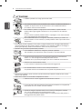
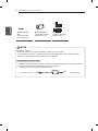
Please read this manual carefully before operating your set and retain it
for future reference.
OWNER’S MANUAL

A-2
TABLE OF CONTENTS
TABLE OF CONTENTS
A-3 SETTING UP THE TV
A-3 Attaching the stand
A-4 Assembling the AV Cover
A-4 Attaching the Video Call Camera
A-5 Tidying cables
A-7 MAKING CONNECTIONS
A-7 Antenna Connection
A-7 Satellite dish Connection
A-8 HDMI Connection
A-8 - ARC (Audio Return Channel)
A-9 DVI to HDMI Connection
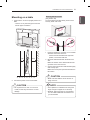
A-10 MHL Connection
A-11 Component Connection
A-12 Composite Connection
A-12 Headphone Connection
A-13 Audio Connection
A-13 - Digital optical audio connection
A-14 - Canvas speaker connection
A-14 USB Connection
A-15 CI module Connection
A-16 Euro Scart Connection
LANGUAGE LIST
English
Italiano
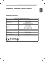
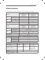
B-1 SPECIFICATIONS
COMMON
COMMON
LANGUAGE

A-3
SETTING UP THE TV
SETTING UP THE TV
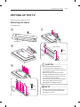
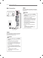
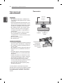
Image shown may differ from your TV.
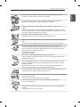
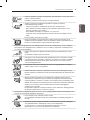
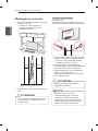
Attaching the stand
(Only EA88**-ZA)
CAUTION
When attaching the stand to the TV
set, place the screen facing down on a
cushioned table or flat surface to protect the
screen from scratches.
Make sure that the screws are inserted
correctly and fastened securely. (If they are
not fastened securely enough, the TV may
tilt forward after being installed.)
Do not use too much force and over tighten
the screws; otherwise screw may be
damaged and not tighten correctly.
NOTE
Remove the stand before installing the TV
on a wall mount by performing the stand
attachment in reverse.
1
2
Stand Base
Front
3
9EA
M4 x L20
4
4EA
M4 x L10
Stand Cover

A-4
SETTING UP THE TV
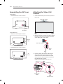
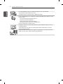
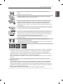
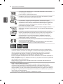
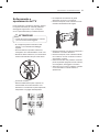
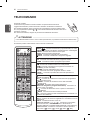
Attaching the Video Call
Camera
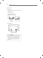
1 Unfold the stand and put it on the top center of
the TV set.
Video call camera
2 Bend the stand of the Video call camera. Attach
the stand of the Video call camera to the back
of the display with a Velcro Tape.
Video call camera
TV
Velcro
Tape
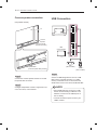
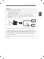
3 Insert the Video call camera’s cable into the
Stand-cable holder. Please open the USB
Camera Cover for Video call camera’s cable
connection.The camera shall be connected to
the CAM terminal as shown.
(Image shown may differ from your TV.)
Stand-cable
holder
USB
Camera Cover
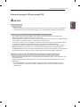
Assembling the AV Cover
(Only EA98**)
1 Assemble the AV Cover as shown.
AV Cover
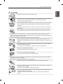
(Only EA88**-ZA)
1 Attach the Velcro Tapes as shown.
Velcro
Tape
2 Assemble the AV Cover as shown.
AV
Cover

A-5
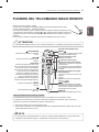
SETTING UP THE TV
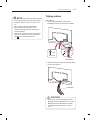
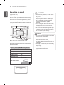
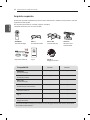
Tidying cables
(Only EA98**)
1 Fix the Cable Management with Cable
Management Screw and arrange the cables.
M4 x L20
1 EA
Cable
Management
2 Wrap the arranged cables with the Cable Band,
then pull the zip down.
Cable Band
CAUTION
Do not move the TV by holding the Cable
Management and Cable Band, as the Cable
Management and Cable Band may break,
and injuries and damage to the TV may
occur.
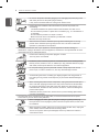
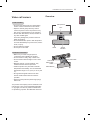
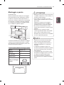
NOTE
For the best quality video and audio outputs,
install the camera on the top-center of your
TV.
Set up with the television switched off.
When using external speakers, allow
sufficient space between the microphones
and the speakers.
Make sure to connect the Video call camera
cable to the CAM port with the USB trident
logo
on the cable facing the front.

A-6
SETTING UP THE TV
(Only EA88**-ZA)
** Stand Type **
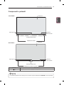
1 Use Cable Holder to neatly secure and position
cables together.
Cable Holder
Power Cable Hoder
** Wall Mount Type **
Power Cable Hoder
CAUTION
Do not move the TV by holding the Cable
Holder and Power Cable Holder, as the
Cable Holder and Power Cable Holder may
break, and injuries and damage to the TV
may occur.

A-7
MAKING CONNECTIONS
MAKING
CONNECTIONS
This section on MAKING CONNECTIONS mainly
uses diagrams for the 55EA98** models.
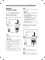
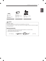
Antenna Connection
Wall Antenna
Socket
IN
ANTENNA/
CABLE
English
Connect the TV to a wall antenna socket with an
RF cable (75 Ω).
NOTE
Use a signal splitter to use more than 2 TVs.
If the image quality is poor, install a signal
amplifier properly to improve the image
quality.
If the image quality is poor with an antenna
connected, try to realign the antenna in the
correct direction.
An antenna cable and converter are not
supplied.
Supported DTV Audio: MPEG, Dolby Digital,
Dolby Digital Plus, HE-AAC
Italiano
Collegare il televisore all’antenna centralizzata con
un cavo RF (75 Ω).
NOTA
Utilizzare uno sdoppiatore del segnale per
usare più di 2 televisori.
Se la qualità dell’immagine è scarsa,
installare correttamente un amplificatore del
segnale per migliorarla.
Se la qualità dell’immagine è scarsa con
un’antenna collegata, provare a riallineare
l’antenna nella direzione corretta.
Il cavo e il convertitore dell’antenna non
sono in dotazione.
Audio DTV supportato: MPEG, Dolby Digital,
Dolby Digital Plus, HE-AAC
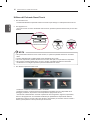
Satellite dish Connection
(Only satellite models)
IN
13 / 18 V
700mA Max
LNB IN
Satellite
Satellite
Dish
English
Connect the TV to a satellite dish to a satellite
socket with a satellite RF cable (75 Ω).
Italiano
Collegare la TV a un’antenna satellitare e a una
presa satellitare con un cavo RF satellitare (75 Ω).

A-8
MAKING CONNECTIONS
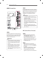
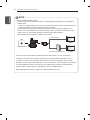
HDMI Connection
HDMI
DVD / Blu-Ray /
HD Cable Box /
HD STB / PC
(*Not Provided)
English
Transmits the digital video and audio signals from
an external device to the TV. Connect the external
device and the TV with the HDMI cable as shown.
Choose any HDMI input port to connect. It does
not matter which port you use.
NOTE
It is recommended to use the TV with the
HDMI connection for the best image quality.
Use the latest High Speed HDMI™ Cable
with CEC (Customer Electronics Control)
function.
High Speed HDMI™ Cables are tested to
carry an HD signal up to 1080p and higher.
Supported HDMI Audio format : Dolby
Digital, DTS, PCM (Up to 192 KHz, 32 KHz
/ 44.1 KHz / 48 KHz / 88 KHz / 96 KHz / 176
KHz / 192 KHz)
Italiano
Il segnale digitale audio e video viene trasmesso
da un dispositivo esterno al televisore. Collegare il
dispositivo esterno e il televisore mediante il cavo
HDMI come mostrato nell’illustrazione di seguito.
Scegliere una porta di ingresso HDMI per il
collegamento. La scelta della porta è libera.
NOTA
Si consiglia di utilizzare il televisore con il
collegamento HDMI per ottenere la migliore
qualità delle immagini.
Utilizzare un cavo HDMI™ ad alta velocità
dotato dei requisiti più recenti con funzione
CEC (Customer Electronics Control).
I cavi HDMI™ ad alta velocità sono testati
per trasmettere un segnale HD fino a 1080p
e superiore.
Formato audio HDMI supportato: Dolby
Digital, DTS, PCM (fino a 192 KHz, 32 KHz
/ 44,1 KHz / 48 KHz / 88 KHz / 96 KHz / 176
KHz / 192 KHz)
ARC (Audio Return Channel)
English
An external audio device that supports
SIMPLINK and ARC must be connected
using HDMI/DVI IN 1 (ARC) port.
When connected with a high-speed HDMI
cable, the external audio device that
supports ARC outputs optical SPDIF without
additional optical audio cable and supports
the SIMPLINK function.
Italiano
Per il collegamento di un dispositivo
audio esterno che supporta le funzionalità
SIMPLINK e ARC, usare la porta HDMI/DVI
IN 1 (ARC).
Se si effettua il collegamento con un cavo
HDMI ad alta velocità, il dispositivo audio
esterno che supporta ARC trasmette
il segnale SPDIF senza il cavo ottico
aggiuntivo e supporta la funzione SIMPLINK.

A-9
MAKING CONNECTIONS
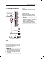
DVI to HDMI Connection
IN
AV2
( Audio in)
DVI OUT
AUDIO OUT
DVD / Blu-Ray / HD Cable Box / PC
(*Not Provided)
English
Transmits the digital video signal from an external
device to the TV. Connect the external device and
the TV with the DVI-HDMI cable as shown. To
transmit an audio signal, connect an audio cable.
Choose any HDMI input port to connect. It does
not matter which port you use.
NOTE
Depending on the graphics card, DOS mode
may not work if a HDMI to DVI Cable is in use.
When using the DVI/HDMI cable, single link
is supported.
Italiano
Il segnale digitale video viene trasmesso da
un dispositivo esterno al televisore. Collegare
il dispositivo esterno e il televisore mediante il
cavo DVI-HDMI come mostrato nell’illustrazione
di seguito. Per trasmettere un segnale audio,
collegare un cavo audio.
Scegliere una porta di ingresso HDMI per il
collegamento. La scelta della porta è libera.
NOTA
A seconda della scheda grafica in uso, la
modalità DOS potrebbe non funzionare se si
utilizza un cavo da HDMI a DVI.
Quando si utilizza il cavo HDMI/DVI, è
supportata solo l’interfaccia Single link.

A-10
MAKING CONNECTIONS
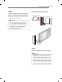
MHL Connection
Mobile phone
(*Not Provided)
MHL passive cable
English
Mobile High-denition Link (MHL) is an interface
for transmitting digital audiovisual signals from
mobile phones to television sets.
NOTE
Connect the mobile phone to the HDMI/DVI
IN 4 (MHL) port to view the phone screen on
the TV.
The MHL passive cable is needed to
connect the TV and a mobile phone.
This only works for the MHL-enabled phone.
Some applications can be operated by the
remote control.
For some mobile phones supporting MHL,
you can control with the magic remote control.
Remove the MHL passive cable from the TV
when:
- The MHL function is disabled
- Your mobile device is fully charged in
standby mode
Italiano
Mobile High-denition Link (MHL) è un’interfaccia
per la trasmissione di segnali audiovisivi digitali dai
cellulari ai TV.
NOTA
Collegare il cellulare alla porta HDMI/DVI
IN 4 (MHL) per visualizzare lo schermo del
telefono sul TV.
È necessario un cavo passivo MHL per
collegare il TV a un cellulare.
Questa funzione è disponibile soltanto sui
telefoni che supportano l’interfaccia MHL.
È possibile utilizzare alcune applicazioni
tramite il telecomando.
Per alcuni cellulari che supportano la
tecnologia MHL, è possibile utilizzare il
telecomando magico.
Rimuovere il cavo passivo MHL dal TV
quando:
- The MHL function is disabled
- Il dispositivo mobile è completamente
carico in modalità standby

A-11
MAKING CONNECTIONS
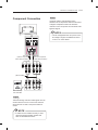
Component Connection
(*Not Provided)
IN
COMPONENT
YPB
AUDIO
AV2
PR
VIDEO
AV2
VIDEO
AUDIO
L R
YELLOW
WHITE
RED
RED
BLUE
GREEN
WHITE WHITE
RED
RED
BLUE
GREEN
RED
RED
BLUE
GREEN
DVD / Blu-Ray /
HD Cable Box
YELLOW
(Use the composite
video cable provided.)
GREEN
(Use the component
video cable provided.)
English
Transmits analog video and audio signals from an
external device to the TV. Connect the external
device and the TV with a component cable as
shown.
NOTE
If cables are not installed correctly, it could
cause this image to display in black and
white or with distorted colours.
Italiano
Il segnale audio e video analogico viene
trasmesso da un dispositivo esterno al televisore.
Collegare il dispositivo esterno al televisore
usando un cavo component come mostrato nella
gura di seguito.
NOTA
L’errato collegamento dei cavi può far sì che
le immagini vengano visualizzate in bianco
e nero o con colori distorti.

A-12
MAKING CONNECTIONS
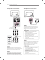
Composite Connection
IN
COMPONENT
YP
B
AUDIO
AV2
P
R
VIDEO
AV2
VIDEO
MONO
( )
AUDIO
L R
VCR / DVD /
Blu-Ray /
HD Cable Box
YELLOW
(Use the composite
video cable provided.)
YELLOW YELLOWYELLOW
WHITE WHITEWHITE
RED REDRED
(*Not Provided)
English
Transmits analog video and audio signals from an
external device to the TV. Connect the external device
and the TV with the composite cable as shown.
Italiano
Il segnale audio e video analogico viene trasmesso
da un dispositivo esterno al televisore. Collegare il
dispositivo esterno e il televisore mediante il cavo
composite come mostrato nell’illustrazione di seguito.
Headphone Connection
(*Not Provided)
OUT
Ext.Speaker /
H/P
English
Transmits the headphone signal from the TV to
an external device. Connect the external device
and the TV with the headphone as shown.
NOTE
AUDIO menu items are disabled when
connecting a headphone.
Optical Digital Audio Out is not available
when connecting a headphone.
Headphone impedance: 16 Ω
Max audio output of headphone: 0.627 mW
to 1.334 mW
Headphone jack size: 0.35 cm
Italiano
Consente la trasmissione del segnale delle cufe
dalla TV a un dispositivo esterno. Collegare il
dispositivo esterno e la TV con le cufe come
mostrato nell’illustrazione di seguito.
NOTA
Le voci del menu AUDIO sono disabilitate
se sono collegate le cuffie.
L’uscita audio ottica digitale non è
disponibile se sono collegate le cuffie.
Impedenza cuffie: 16 Ω
Uscita audio max delle cuffie: da 0,627 mW
a 1,334 mW
Dimensioni jack per cuffia: 0,35 cm

A-13
MAKING CONNECTIONS
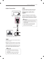
Audio Connection
(*Not Provided)
OUT
OPTICAL
DIGITAL
AUDIO
OPTICAL
AUDIO IN
Digital Audio System /
Canvas Speaker (Only EA88**-ZC/ZF)
English
You may use an external audio system instead of
the built-in speaker.
Digital optical audio connection
Transmits a digital audio signal from the TV to an
external device. Connect the external device and
the TV with the optical audio cable as shown.
NOTE
Do not look into the optical output port.
Looking at the laser beam may damage
your vision.
Audio with ACP (Audio Copy Protection)
function may block digital audio output.
Italiano
È possibile utilizzare un sistema audio esterno
opzionale al posto dell’altoparlante integrato.
Collegamento audio ottico
digitale
Il segnale audio digitale viene trasmesso dal
televisore su un dispositivo esterno. Collegare il
dispositivo esterno e il televisore con il cavo audio
ottico come mostrato nell’illustrazione di seguito.
NOTA
Non guardare nella porta dell’uscita ottica.
Guardare il raggio laser potrebbe provocare
danni alla vista.
Contenuti audio con funzione anticopia
(ACP, Audio Copy Protection) possono
bloccare l’uscita audio digitale.

A-14
MAKING CONNECTIONS
Canvas speaker connection
(Only EA88**-ZC/ZF)
TV
Optical cable
(Use the Optical cable provided.)
(Use the Canvas
Speaker provided.)
Canvas
Speaker
English
Connect the Canvas speaker and the TV set with
the optical cable as shown.
Italiano
Collegare l’altoparlante canvas e l’apparecchio TV
con il cavo ottico, come mostrato.
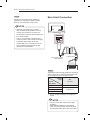
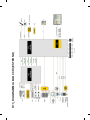
USB Connection
USB IN
1
2
HDD IN
(USB 3.0 IN)
3
USB IN
PCMCIA CARD
S
L
OT
HDD
(*Not Provided)
Hub
(*Not Provided)
USB
(*Not Provided)
English
Connect a USB storage device such as a USB
ash memory, external hard drive, or a USB
memory card reader to the TV and access the
Smart Share menu to use various multimedia les.
NOTE
Some USB Hubs may not work. If a USB
device connected using a USB Hub is not
detected, connect it to the USB IN port on
the TV directly.
Connect the external power source if your
USB is needed.

A-15
MAKING CONNECTIONS
Italiano
Collegare una periferica di archiviazione USB, ad
esempio una memoria ash USB, un hard disk
esterno, o un lettore di schede di memoria USB
al televisore e accedere al menu Smart Share per
utilizzare diversi le multimediali.
NOTA
Alcuni hub USB potrebbero non funzionare.
Se una periferica USB collegata tramite
un hub USB non viene rilevata, collegarla
direttamente alla porta USB della TV.
Collegarsi all’alimentazione esterna se il
dispositivo USB lo richiede.
CI module Connection
PCMCIA CARD SLOT
(*Not Provided)
PCMCIA CARD SLOT
English
View the encrypted (pay) services in digital TV
mode. This feature is not available in all countries.
NOTE
Check if the CI module is inserted into the
PCMCIA card slot in the right direction. If the
module is not inserted properly, this can cause
damage to the TV and the PCMCIA card slot.
If the TV does not display any video and audio
when CI+ CAM is connected, please contact to
the Terrestrial/Cable/Satellite Service Operator.

A-16
MAKING CONNECTIONS
Italiano
Consente la visione dei servizi codicati (a
pagamento) in modalità TV digitale. Questa
funzione non è disponibile in tutti i paesi.
NOTA
Verificare che il modulo CI sia inserito
nello slot della scheda PCMCIA nel verso
corretto. Se il modulo non è inserito nel
modo corretto, possono verificarsi danni alla
TV e allo slot stesso.
Se il TV non visualizza o riproduce alcun
contenuto video e audio quando è collegata
la funzione CAM (modulo di accesso
condizionale) con CI+ (Interfaccia comune
plus), contattare l’operatore del servizio
terrestre/via cavo/satellitare.
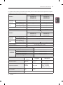
Euro Scart Connection
AUDIO / VIDEO
IN/OUT
(RGB)
AV 1
(*Not Provided)
(Use the Scart gender
cable provided.)
English
Transmits the video and audio signals from an external
device to the TV set. Connect the external device and
the TV set with the euro scart cable as shown.
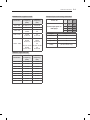
Output
Type
Current
input mode
AV1
(TV Out
1
)
Digital TV Digital TV
Analogue TV, AV
Analogue TVComponent
HDMI
1 TV Out : Outputs Analogue TV or Digital TV
signals.
NOTE
Any Euro scart cable used must be signal
shielded.
When watching digital TV in 3D imaging
mode, only 2D out signals cannot be output
through the SCART cable. (Only 3D models)

A-17
MAKING CONNECTIONS
Italiano
Consente la trasmissione dei segnali audio e video
da un dispositivo esterno al televisore. Collegare il
dispositivo esterno e il televisore con il cavo Euro
Scart come mostrato nell’illustrazione di seguito.
Tipo di uscita
Modalità
di ingresso
corrente
AV1
(Uscita TV
1
)
TV digitale TV digitale
TV analogica, AV
TV analogicaComponent
HDMI
1 Uscita TV: uscite segnali TV analogica o TV
digitale.
NOTA
I cavi Euro Scart devono essere schermati.
Quando si guarda il TV digitale in modalità
immagini 3D, solo i segnali di uscita 2D
possono passare attraverso il cavo SCART.
(Solo modelli 3D)
English
Connect various external devices to the TV
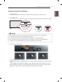
and switch input modes to select an external
device. For more information of external device’s
connection, refer to the manual provided with each
device.
Available external devices are: HD receivers,
DVD players, VCRs, audio systems, USB storage
devices, PC, gaming devices, and other external
devices.
NOTE
The external device connection may differ
from the model.
Connect external devices to the TV
regardless of the order of the TV port.
If you record a TV program on a DVD
recorder or VCR, make sure to connect the
TV signal input cable to the TV through a
DVD recorder or VCR. For more information
of recording, refer to the manual provided
with the connected device.
Refer to the external equipment’s manual for
operating instructions.
If you connect a gaming device to the TV,
use the cable supplied with the gaming
device.
In PC mode, there may be noise associated
with the resolution, vertical pattern, contrast
or brightness. If noise is present, change
the PC output to another resolution, change
the refresh rate to another rate or adjust the
brightness and contrast on the PICTURE
menu until the picture is clear.
In PC mode, some resolution settings may
not work properly depending on the graphics
card.

A-18
MAKING CONNECTIONS
Italiano
Collegare diversi dispositivi esterni al televisore e
modicare la modalità di ingresso per selezionare
un dispositivo esterno. Per ulteriori informazioni
sul collegamento di un dispositivo esterno,
consultare il manuale fornito in dotazione con
ciascun dispositivo.
È possibile collegare i seguenti dispositivi esterni:
ricevitori HD, lettori DVD, VCR, sistemi audio,
periferiche di archiviazione USB, PC, console per
videogiochi e altri dispositivi esterni.
NOTA
Il collegamento del dispositivo esterno può
variare in base al modello.
Collegare i dispositivi esterni al televisore
a prescindere dall’ordine della porta del
televisore.
Se si registra un programma TV su un
registratore DVD o VCR, accertarsi di
collegare il cavo di ingresso del segnale al
televisore attraverso un registratore DVD
o VCR. Per ulteriori informazioni sulla
registrazione, consultare il manuale fornito
in dotazione con il dispositivo collegato.
Consultare il manuale dell’apparecchiatura
esterna per le istruzioni operative.
Se si collega una console per videogiochi
alla TV, utilizzare il cavo fornito con il
dispositivo.
In modalità PC, possono essere presenti
interferenze relative alla risoluzione, schemi
verticali, contrasto o luminosità. In caso
di interferenze, modificare la modalità
PC impostando un’altra risoluzione o
modificando la frequenza di aggiornamento
oppure regolare luminosità e contrasto
sul menu IMMAGINE finché non si ottiene
un’immagine nitida.
A seconda della scheda grafica utilizzata,
alcune impostazioni di risoluzione
potrebbero non essere adatte alla modalità
PC.

www.lg.com
OWNER’S MANUAL
OLED TV
Please read this manual carefully before operating your set and retain it
for future reference.

2
ENG
ENGLISH
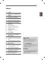
TABLE OF CONTENTS
TABLE OF CONTENTS
3 LICENSES
3 OPEN SOURCE SOFTWARE NOTICE
4 SAFETY INSTRUCTIONS
10 - Viewing 3D Imaging (Only 3D models)
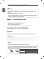
12 INSTALLATION PROCEDURE
12 ASSEMBLING AND PREPARING
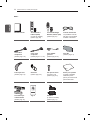
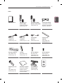
12 Unpacking
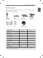
17 Separate purchase
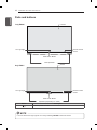
18 Parts and buttons
19 - Using the Smart Touch Button
20 Lifting and moving the TV
21 Mounting on a table
22 Mounting on a wall
23 Video call camera
23 - Overview
25 REMOTE CONTROL
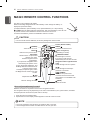
26 MAGIC REMOTE CONTROL
FUNCTIONS
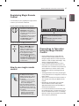
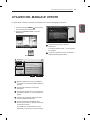
27 Registering Magic Remote Control
27 How to use magic remote control
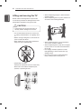
27 Precautions to Take when Using the Magic
Remote Control
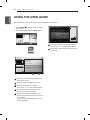
28 USING THE USER GUIDE
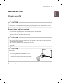
29 MAINTENANCE
29 Cleaning your TV
29 - Screen, frame, cabinet and stand
29 - Power cord
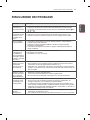
30 TROUBLESHOOTING
31 EXTERNAL CONTROL DEVICE
SETUP
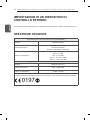
31 SPECIFICATIONS
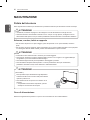
WARNING
If you ignore the warning message, you may
be seriously injured or there is a possibility
of accident or death.
CAUTION
If you ignore the caution message, you may
be slightly injured or the product may be
damaged.
NOTE
The note helps you understand and use
the product safely. Please read the note
carefully before using the product.
La pagina si sta caricando...
La pagina si sta caricando...
La pagina si sta caricando...
La pagina si sta caricando...
La pagina si sta caricando...
La pagina si sta caricando...
La pagina si sta caricando...
La pagina si sta caricando...
La pagina si sta caricando...
La pagina si sta caricando...
La pagina si sta caricando...
La pagina si sta caricando...
La pagina si sta caricando...
La pagina si sta caricando...
La pagina si sta caricando...
La pagina si sta caricando...
La pagina si sta caricando...
La pagina si sta caricando...
La pagina si sta caricando...
La pagina si sta caricando...
La pagina si sta caricando...
La pagina si sta caricando...
La pagina si sta caricando...
La pagina si sta caricando...
La pagina si sta caricando...
La pagina si sta caricando...
La pagina si sta caricando...
La pagina si sta caricando...
La pagina si sta caricando...
La pagina si sta caricando...
La pagina si sta caricando...
La pagina si sta caricando...
La pagina si sta caricando...
La pagina si sta caricando...
La pagina si sta caricando...
La pagina si sta caricando...
La pagina si sta caricando...
La pagina si sta caricando...
La pagina si sta caricando...
La pagina si sta caricando...
La pagina si sta caricando...
La pagina si sta caricando...
La pagina si sta caricando...
La pagina si sta caricando...
La pagina si sta caricando...
La pagina si sta caricando...
La pagina si sta caricando...
La pagina si sta caricando...
La pagina si sta caricando...
La pagina si sta caricando...
La pagina si sta caricando...
La pagina si sta caricando...
La pagina si sta caricando...
La pagina si sta caricando...
La pagina si sta caricando...
La pagina si sta caricando...
La pagina si sta caricando...
La pagina si sta caricando...
La pagina si sta caricando...
La pagina si sta caricando...
La pagina si sta caricando...
La pagina si sta caricando...
La pagina si sta caricando...
La pagina si sta caricando...
La pagina si sta caricando...
La pagina si sta caricando...
La pagina si sta caricando...
La pagina si sta caricando...
La pagina si sta caricando...
La pagina si sta caricando...
La pagina si sta caricando...
La pagina si sta caricando...
-
 1
1
-
 2
2
-
 3
3
-
 4
4
-
 5
5
-
 6
6
-
 7
7
-
 8
8
-
 9
9
-
 10
10
-
 11
11
-
 12
12
-
 13
13
-
 14
14
-
 15
15
-
 16
16
-
 17
17
-
 18
18
-
 19
19
-
 20
20
-
 21
21
-
 22
22
-
 23
23
-
 24
24
-
 25
25
-
 26
26
-
 27
27
-
 28
28
-
 29
29
-
 30
30
-
 31
31
-
 32
32
-
 33
33
-
 34
34
-
 35
35
-
 36
36
-
 37
37
-
 38
38
-
 39
39
-
 40
40
-
 41
41
-
 42
42
-
 43
43
-
 44
44
-
 45
45
-
 46
46
-
 47
47
-
 48
48
-
 49
49
-
 50
50
-
 51
51
-
 52
52
-
 53
53
-
 54
54
-
 55
55
-
 56
56
-
 57
57
-
 58
58
-
 59
59
-
 60
60
-
 61
61
-
 62
62
-
 63
63
-
 64
64
-
 65
65
-
 66
66
-
 67
67
-
 68
68
-
 69
69
-
 70
70
-
 71
71
-
 72
72
-
 73
73
-
 74
74
-
 75
75
-
 76
76
-
 77
77
-
 78
78
-
 79
79
-
 80
80
-
 81
81
-
 82
82
-
 83
83
-
 84
84
-
 85
85
-
 86
86
-
 87
87
-
 88
88
-
 89
89
-
 90
90
-
 91
91
-
 92
92


in altre lingue
- English: LG 55EA980V User manual
Documenti correlati
-
LG OLED77G6V Manuale utente
-
LG 42LM671S Manuale del proprietario
-
LG 55EA970V Manuale del proprietario
-
LG 60PA660S Manuale utente
-
LG 29LN457B Manuale utente
-
-
-
LG 55EA9809 Manuale utente
-
LG LG 55EA970V Manuale utente
-
LG 55EA980V Manuale del proprietario