REHM TIGER 170 Operating Instructions Manual
- Categoria
- Sistema di saldatura
- Tipo
- Operating Instructions Manual


1
Product Identification
Description TIG Inverter
Article number
Type TIGER 170 150 3170
TIGER 170 - Set 150 3171
TIGER 210 140 2180
Manufacturer REHM GmbH u. Co Schweißtechnik
Otto Straße 2
D-73066 Uhingen
Telephone No.: 0049 (07161) 3007-0
Telefax No.: 0049 (07161) 3007-20
E-mail: rehm@rehm-online.de
Internet: http://www.rehm-online.de
Document Number. 730 1352
Date of Issue. 06.2013
© REHM GmbH u. Co Schweißtechnik, Uhingen, Germany. 2002
The contents of this document is the exclusive property of the REHM GmbH
u. Co Schweißtechnik. The transfer of this information to a third party or the
copying of this document, using the contents other than for the purpose
intended is strictly forbidden, unless otherwise agreed to in writing by the
company. Failure to comply with this condition in full will result in legal action
against the person or company committing the offence. All rights referring to
Patents whether actual or applied for, are reserved.
Using this information for the purposes of production is expressly forbidden.
We reserve the right to alter the contents of this document without prior
notice.

2
GB
1 General description
Valued Customer,
Congratulations!, You have just purchased a REHM welding inverter unit, a top quality
product Made in Germany. We thank you for the confidence you have placed in our product
and hope that it brings you many years of reliable service.
The TIGER 170 / 210 is a real power-house, compact in size and weighing a mere 4.9 kg /
6.0 kg. The robust housing makes the TIGER 170 / 210 the ideal companion for coping with
the arduous working conditions on-site. Nevertheless, the TIGER 170 / 210 has all of the
attributes associated with professional units:
- 170 A /210 A TIG welding current with 50% duty cycle
- Selectable HF ignition On/Off
- Adjustable current downslope and post-flow gas time
- Latch and Non-latch torch trigger operation
- Integrated remote control socket with dust cover as standard
- INTIG-Energy (Intelligent Ignition Energy) – intelligent ignition energy control sequence
for TIG and electrode functions
- EPC (Electronic Power Control) – continuous electronic mains voltage monitoring
- BOOSTER function – 150 A / 170 A electrode welding current at a 55% / 90% duty cycle
- Fuse hold function – electronic monitoring of current load prevents main fuse tripping
- Anti-stick function – prevents electrode overheating in the event of accidental sticking
- ELSA system (Electronic Stabilised Arc) – eliminates undesired interruptions in welding
even with mains supply cables up to 100m long
- Temperature-controlled cooling fan – for automatic cooling of the power source
These TIGER 170 / 210 welding unit is based on Primary switched inverter power supply.
The ingress protection classification is IP23. The unit is designed for use in difficult
environmental conditions. Furthermore it is designed for the TIG and MMA welding process,
and is suitable for welding work of stainless, alloy and low-alloyed steels.

3
2 The following safety precautions must be taken
Dry protective clothing must be worn. The eyes and face must be protected by welding
goggles.
The unit must only be used and operated using earthed power sockets and mains cables
with the earth conductors properly connected in accordance with the local electrical
regulations.
The unit must only be maintained and serviced by suitably trained and qualified staff.
In the event of problems, please contact REHM Customer Service on +49 7161 3007-85.
Accident Prevention Regulation "Welding, Cutting and Related Processes“ (BGR 500) must
be observed during the operation of this unit. The main hazards to be observed are:
Fire and explosion
Harmful substances (gases, fumes, smoke / dust)
Ultra violet radiation
Electrical hazards
Operator errors
The units are intended for stick electrode welding (MMA) and TIG welding. They must be
operated only by personnel who have been correctly trained and are qualified in the use and
maintenance of such welding equipment.
The unit is designed in accordance with EN 55011 for Group 2 Class A and is suitable for
use in all areas, with the exception of residential areas and premises directly connected to a
low voltage network which also supplies residential buildings.

4
GB
3 Interpretation of machine indications and symbols
3.1 The REHM control panel
3.1.1 Summary
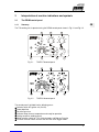
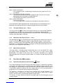
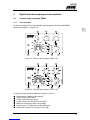
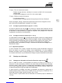
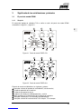
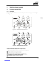
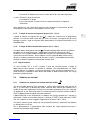
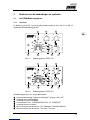
The TIG welding unit is operated using the REHM control panel shown in Fig. 3.1 and Fig. 3.2.
0
2
4 6
8
10
sec
A
730 0641
5
20
40
60 80
120
140
150
170
100
0,5
5
10 15
20
25
sec
5
231
6 74
Fig. 3.1 TIGER 170 control panel
Fig. 3.2 TIGER 210 control panel
The control panel is divided into the following areas:
Selector switch HF ignition unit (On/Off)
Downslope time
Post-flow gas time
Indicator lamps for over-temperature and ready for operation
Setting control for welding current
Mode selection switch for: TIG, Stick-electrode, and Booster-Function
Function selection switch for latch and non-latch torch trigger modes

5
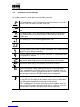
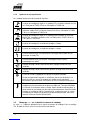
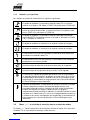
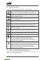
3.1.2 The symbols and their meanings
The symbols used on the control panel have the following meanings:
The welding mode is set to TIG welding. The maximum current is up to 170 A
for the TIGER 170 and 210 A for the TIGER 210.
The welding mode is set to stick-electrode welding with Fuse Hold function. The
maximum current is up to 140 A for the TIGER 170 and 160 A for the TIGER
210.
The welding mode is set to stick-electrode welding with BOOSTER function.
The maximum current is up to 150 A for the TIGER 170 and 170 A for the
TIGER 210.
The welding unit is in the latched trigger operation mode.
The welding unit is in the non-latched trigger operation mode.
The high frequency (HF) ignition system is switched ON, this is for non-contact
ignition of the arc during TIG welding.
The high frequency (HF) ignition system is switched OFF. Program controlled
Lift-Arc-Ignition is activated.
Adjustment of downslope (crater fill) time (between 0.0 and 10.0 seconds).
Adjustment of post-flow gas time (between 0.5 and 25.0 seconds).
Open-circuit voltage is being supplied to the torch or the electrode holder.
If this symbol flashes, the internal monitoring system has tripped. Switch the
mains switch OFF and then ON again to reset the unit. If this fails to clear the
fault then please contact the REHM Customer Service Department.
Machine temperature indicator. The yellow LED lights up when the maximum
permitted operating temperature of the machine has been exceeded. As long
as the LED is ON, the output will be inhibited. After the unit has cooled down,
the LED goes out automatically and welding can be restarted.
If this symbol flashes, the internal monitoring system has tripped. Switch the
mains switch OFF and then ON again to reset the unit. If this fails to clear the
fault then please contact the REHM Customer Service Department.

6
GB
3.2 „ + ” Marking on the welding current socket
The „ + “ sign indicates the positive pole of the welding power source. The earth cable is
connected to this socket when TIG welding.
3.3 „ – “ Marking on the welding current socket
The „ - “ sign indicates the negative pole of the welding power source. The torch is
connected to this socket when TIG welding.
4 Mains power supply
The welding unit must be fitted with the correct mains supply plug which fully complies with
the International electrical standards and the local electrical regulations. The unit must only
be operated with fuses or circuit breakers with a maximum current rating of 16A. When the
mains power is switched on, the mains ON/OFF switch on the back of the unit is illuminates.
If the TIGER 170 is switched ON and OFF frequently (in quick succession), the unit may
automatically switch over to the power supply protection mode. In this mode, the unit cannot
be re-started and the green indicator lamp flashes. If this occurs, switch the unit OFF and
wait for approx. 2 minutes. The unit can then be restarted.
5 Installation
Care should be taken during installation of the unit to ensure that the ventilation slots are not
covered and the area where the machine is to be used affords a protection classification of
IP23.
6 Description of Welding processes
6.1 TIG Welding
6.1.1 Principle of the TIG welding process
The unit supplies a current up to 170 A DC for the TIGER 170 and 210 A for the TIGER 210
for TIG welding. The mains current limiting function is inactive during the TIG welding mode.
Despite the higher output current, the power drawn from the mains supply is lower than
required for stick electrode welding; the mains fuse is therefore unlikely to trip-out during TIG
welding.
During TIG welding, a welding arc is established between a tungsten electrode and the
workpiece. The shielding gas normally used is an inert gas such as pure Argon, Helium or a
mixture of both.
The negative pole of the power supply is connected to the tungsten electrode, the positive
pole is connected to the workpiece. The tungsten electrode is the conductor and the current
carrier (non-consumable electrode). The filler metal required is fed manually in the form of a
rod or by a separate cold wire feed unit. The tungsten electrode, and the welding pool is
protected from the atmosphere by the inert shielding gas supplied from the gas nozzle.

7
6.1.2 Arc ignition with INTIG Energy
The highly intelligent processor ensures that the ideal ignition energy is automatically chosen
depending upon the actual weld current setting, this applies not only for HF, but also for the
Lift-Arc ignition sequence.
When the selector switch is set to position ´"HF On", the high-frequency ignition unit is
ready for operation. To ignite the arc, the electrode must be held about 3 to 5 mm above the
workpiece. When the torch button is pressed, the shielding gas is pre-ionised by a high-
voltage, the current flows between the end of the electrode and the workpiece so that the
main arc is established. The ignition of the arc without contact between the tungsten
electrode prevents tungsten inclusion in the weld. once the arc has successfully been ignited
the high-frequency ignition unit is switched off automatically during welding.
When the selector switch is set to position "HF Off", contact ignition can also be carried
out using the processor control ignition system (Lift Arc) to strike the arc. In order to ignite the
welding arc, the tip of the electrode must be placed on the workpiece and the torch button
depressed. The processor control system reduces the ignition current so that the tip of the
electrode does not heat up. The electrode is then gradually lifted away from the workpiece,
this action ignites the arc under the system processor control, this results in arc ignition
without HF and also minimum wear on the tungsten electrode. This process is essential
when welding in areas where sensitive electronic equipment is in operation (e.g. repair welds
on CNC-controlled machines) and where there may be a risk of damage caused by high-
voltage.
When the selector switch is set to position "Electrode“, the HF ignition system is
automatically disabled.
The electrode diameter depends on the welding current. A diameter of 1.6 mm is
recommended for welding currents up to 70 A and 2.4 mm for higher currents.
6.1.3 The Non-latch torch button operation mode sequence
Step 1: Activate torch button
° The solenoid valve for the shielding gas is energised
° The arc ignition cycle starts after the fixed gas pre-flow time (0.1 sec.) has elapsed
° The set welding current is automatically reached after the up-slope time (0.1 sec)
has elapsed.
Step 2: Release torch button
° The current falls to 20% of the set welding current after the down-slope time has
elapsed, the arc is then automatically switched off.
° The shielding gas continues to flow for the duration of set gas post-flow time.
Non-latched welding mode is recommended for rapid, controlled tacking and manual spot
welding.
6.1.4 The Latched torch button operation mode sequence
Step 1: Activate the torch button
° The solenoid valve for the shielding gas is energised
° The arc ignition cycle starts after the fixed gas pre-flow time (0.1 sec.) has elapsed
° The welding current rises to 50% of the value set on the main current potentiometer

8
GB
Step 2: Release torch button
° The set welding current is automatically reached after the up-slope time (0.1 sec)
has elapsed.
Step 3: Activate the torch button once again
° The welding current falls to 20% of the welding current set on the main current
potentiometer for the duration of the downslope time
° The welding current remains at this 20% level.
Step 4: Release torch button
° The arc is extinguished
° The shielding gas continues to flow for the duration of the gas post-flow time.
In the latched torch button operation mode, the operator does not need to keep the torch
button pressed, allowing welding for a relatively long period of time without fatigue.
6.1.5 Gas post-flow timer (0.5 s – 25.0 s)
The gas post-flow time is the time which elapses after the arc is extinguished and before
the shielding gas solenoid valve is de-energised. The shielding gas protects both the
workpiece and the tungsten electrode from contamination form the surrounding atmosphere
until they have cooled down sufficiently.
6.1.6 Downslope timer Crater fill (0.0 s – 10.0 s)
The downslope timer is the time during which the welding current decays to the crater fill
current. In the Non-latched operation mode, the downslope time begins as soon as torch
button 1 is released. In the Latched operation mode, the downslope time commences when
torch button 1 is activated during welding. The longer the setting of the downslope time, the
lower the risk of creating end crater cracking.
6.1.7 Manual Pulsing function
If the torch button is activated during the downslope when in the non-latched TIG 2 mode,
the welding current immediately rises to the value set on the main current setting
potentiometer. The length of each pulse and is manually controlled by the operator
depending upon when he activates the torch button, as a result the average heat input will be
reduced.
6.2 Stick Electrode (MMA) welding
6.2.1 Stick Electrode welding in the Fuse Hold mode
In this mode of operation, the actual current drawn from the mains is continuously monitored.
If necessary, the welding current is reduced to the level required to prevent the mains fuse
form tripping out. A quick acting miniature circuit breaker similar to the type normally installed
in households should be installed in the mains supply cabinet as the Fuse Hold function is
designed for use in conjunction with this type of circuit breaker.
The machine is designed for use with all the common types of stick electrodes. The
maximum current is 140 A for the TIGER 170 and 160 A for the TIGER 210. If a higher
current is set, the current is automatically limited to 140 A / 160 A.
This current is usually sufficient to weld most common types of stick electrodes of up to
3.25mm diameter.

9
For the precise selection of the electrode polarity and current settings for individual
electrodes, please refer to the electrode manufacturer's instructions.
If for some reason there is a permanent short circuit between the electrode and the
workpiece, the Anti-Stick Function will automatically operate after approx. 1.3s, this then
limits the output current to approx. 35 A.
6.2.2 Stick Electrode welding with the BOOSTER Mode
In this mode of operation, the mains fuse monitoring function is automatically de-activated.
The maximum possible welding current is then 150 A for the TIGER 170 and 170 A for the
TIGER 210. If a higher current is selected, the welding current output is automatically limited
to 150 A /170 A.
6.2.3 Anti-Stick Function
If there is a permanent short circuit between the electrode and the workpiece during welding,
the Anti-Stick Function is automatically activated after approx. 1.3s. This function
automatically limits the welding current to approx. 35 A. This prevents the electrode from
overheating and burning out. The operator terminates the short circuit simply by removing
the contact between the electrode and the workpiece.
6.2.4 INTIG Energy for electrode welding
The INTIG energy (Intelligent Ignition Energy) automatically pre-sets a high power ignition
current sequence, which ensures reliable and smooth ignition when stick electrode welding.
Electrode sticking is prevented during re-ignition even with basic electrodes as the high
power ignition current pulse is only activated as the electrode is lifted off following contact
between the electrode and the workpiece, (similar to the Lift-Arc function for TIG welding).
7. Remote control units
7.1 TIG PLUS 1 foot-operated remote current control unit
(Article No. 753 1001)
The TIG PLUS 1 remote control unit is equipped with a foot-pedal for the infinitely varying the
output current during welding. When the pedal is fully depressed, the welding current
reaches the full value pre-set on the machine. The machine can therefore be set to the
maximum current required, allowing optimum resolution over the required operating current
range.
The TIG PLUS 1 remote control unit also incorporates a rocker switch which has the
following function:
- Hand control signal
The welding current is switched on and off using the torch button; the non-latch and latched
functions as well as the downslope time are active and can be selected on the machine. The
foot pedal controls the welding current, it is not de-activated! This type of operation is
intended for mass production applications where the welding current usually remains
constant and only needs to be reduced slightly from time to time. The current ramping
functions which are active in this mode of operation are therefore beneficial.

10
GB
- Foot control signal
In this mode of operation the welding current is switched on and off using the pedal and is
controlled by the operator using his foot. The welding machine automatically operates in the
non-latch mode only. The upslope and downslope times are automatically set to their
minimum values.
Warning: Ensure that accidental operation of the machine is prevented by accidentally
depressing the foot switch. When the foot pedal is activated, there is a danger of electric
shock caused by the high voltage pulses generated by the welding set!
7.2 TIG PLUS 2 hand-operated remote control unit (order no. 753 1002)
The TIG PLUS 2 hand-operated remote control unit allows the welding current to be adjusted
not only before but also during the welding operation. When the hand regulator is set to
100%, the welding current reaches the full value set on the welding output potentiometer on
the machine. The machine can therefore be set to the maximum current required, allowing
optimum resolution in the required current range. The welding current is switched on and off
using the torch button; the Non-latch and latched operating modes as well as the downslope
time are active and can be selected on the machine.
7.3 REHM SR17/4m torch with current control potentiometer and leather
outer cover (Article No. 763 1711)
The REHM R-SR17/4m TIG torch with current control potentiometer and leather outer cover
offers the same functionality as the hand-operated remote control unit described in Section
7.2 above. The welding current can be set and adjusted, prior to and during welding using
the adjustment potentiometer which is integrated within the torch handle. The torch is
connected to the standard torch control and remote control sockets of the TIGER 170/210.
The REHM R-SR17/4m TIG torch with current control potentiometer and leather outer cover
is specifically designed for use with the electronic control of the TIGER 170/210.
WARNING: The use of any other TIG torches with remote control functions except those
specifically supplied by REHM on the TIGER 170 will void the manufacturers warranty.
7.4 TIGER 170 SET (Article No. 150 3171)
TIGER 170 complete in a metal carrying case, together with the REHM R-SR 17/8m torch
with leather outer sleeve and integrated current setting potentiometer. Pressure regulator,
and Workpiece return cable 4m long. The carrying case is of a robust design and affords
protection for the welding machine and accessories. The case is fitted with high quality
catches which can be locked. The unit has very modest dimensions (Lx B x H: 565 x 360 x
200 mm) and weighs a mere 18 kg, making it the ideal companion for the arduous life in the
workshop as well as the building site.
8. Limitations of Application
The units can be used in any environmental conditions which afford protection corresponding
to Protection Classification IP23 or less. For welding in certain locations (e.g. stables), the
Protection Classification of the welding units has to meet special requirements. The use of

11
machines in such an environments should be carefully examined on a case by case basis.
The units are not designed for multi-shift operation.
9. Maintenance
The units do not require regular maintenance However the condition of the electrical cables
and plugs must be checked before using the machine.
9.1 Proper waste disposal
Only for EU countries.
Do not dispose of electric tools together with household waste material.
In observance of European Directive 2002/96/EC on waste electrical and
electronic equipment and its implementation in accordance with national
law, electric tools that have reached the end of their life must be collected
separately and returned to an environmentally compatible recycling facility.
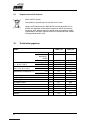
10. Technical data
Model
TIGER 170
TIGER 210
Setting range
TIG
[A]
5 - 170
5 - 210
Electrode in
fuse-hold mode
[A]
5 - 140
5 - 160
Electrode in
BOOSTER mode
[A]
5 - 150
5 - 170
Duty cycle (DC) at
TIG
[%]
50 (30)
50 (30)
I max. by 20°C (40°C)
Electrode
[%]
60 (35)
90 (35)
Welding current at
TIG
[A]
135 (100)
175 (140)
100% DC 20°C (40°C)
Electrode
[A]
120 (100)
160 (120)
Power consumption at I max.
TIG
[kVA]
5,4
4,8
Electrode
[kVA]
5,9
5,5
Main supply voltage
230V/50Hz
230V/50Hz
Main supply voltage
compensation
-15% +10%
-15% +10%
Fuse
[A]
16
16
Power Factor
cos
0,7
0,99
Protection class
IP 23
IP 23
Insulation class
H
H
Torch cooling
Gas
Gas
Dimensions L/W/H
[mm]
320/145/170
375/145/180
Weight
[kg]
4,9
6,0

12
GB
EC Declaration of Conformity
We hereby confirm that the following products
TIGER 170
TIGER 170 – Set
TIGER 210
meet all the major protection requirements laid down in the Council Directive 2004/108/EC
(EMC directive) on the approximation of the laws of the Member States relating to
electromagnetic compatibility and stipulated in the Directive 2006/95/EC relating to electrical
equipment designed for use within certain voltage limits.
The aforementioned products comply with the provisions of this Directive and meet the safety
requirements applicable to equipment for arc welding in accordance with the following
product standards:
EN 60 974-1: 2006-07
Arc welding equipment – Part 1: Welding power sources
EN 60 974-3: 2004-04
Arc welding equipment – Part 3: Arc striking and stabilizing devices
EN 60974-10: 2004-01
Arc welding equipment – Part 10: Electromagnetic compatibility (EMC) requirements
According to EC Directive 2006/42/EG Article 1, para. 2, the above products come
exclusively within the scope of Directive 2006/95/EC relating to electrical equipment
designed for use within certain voltage limits.
This declaration is made on behalf of the manufacturer:
REHM GmbH u. Co. KG Schweißtechnik
Ottostr. 2
73066 Uhingen Germany
Uhingen, 12th June 2007
Declaration made by
R. Stumpp
Managing Director

13
Identification du produit
Désignation inverter primaire Tig
référence REHM
Type TIGER 170 150 3170
TIGER 170 set 150 3171
TIGER 210 140 2180
Fabricant REHM GmbH u. Co Schweißtechnik
Otto Straße 2
D-73066 Uhingen
Téléphone: 0049 (07161) 3007-0
Télécopie: 0049 (07161) 3007-20
Courriel: rehm@rehm-online-de
Internet: http://www.rehm-online.de
Doc. n°: 730 1352
Date d’édition: 06.2013
© REHM GmbH u. Co Schweißtechnik, Uhingen, Alemagne 2002.
Le contenu de la présente description est la propriété exclusive de la société
REHM GmbH u. Co.
La transmission ainsi que la reproduction du présent document, l’exploitation
et la communication de son contenu sont interdites sauf autorisation
explicite.
Toute transgression entraîne l’obligation de réparer le dommage. Tous droits
réservés en cas de dépôt de brevet, de modèle d’utilité ou de dessin.
Une fabrication à partir de ces documents est interdite.
Sous réserve de modifications.

14
F
1 Description générale
Cher Client,
Vous avez fait l’acquisition d’un poste de soudage type inverseur REHM et donc d’un
appareil de marque allemand. Nous vous remercions de la confiance que vous placez dans
nos produits de qualité.
Le TIGER 170 / 210 est un véritable paquet d’énergie, et ce pour un poids de seulement 4,9
kg / 6,0 kg et des dimensions des plus réduites. Avec son habillage robuste, le TIGER 170 /
210 est ainsi le parfait assistant dans les durs travaux de chantier à l’extérieur. De même en
atelier, le nouveau poste de soudage à l’arc TIG présente toutes les qualités que vous
pouvez attendre d’un appareil professionnel :
- courant TIG de 170 A / 210 A pour un facteur de service de 50 %
- amorçage HF pouvant être désactivé
- temps de baisse de courant et de post-émission de gaz réglables
- fonction 2 temps ou 4 temps au choix
- douille de télécommande intégrée de série avec capuchon
- INTIG-Energy (Intelligent Ignition Energy) – la forme intelligente de commande de
l’énergie d’amorçage pour les fonctions TIG et Électrode
- EPC (Electronic Power Control) – surveillance électronique permanente de la tension du
secteur
- fonction BOOSTER – courant d’électrode de 150 A / 170 A pour un facteur de service de
55 % / 90 %
- fonction Protection coupe-circuit – pas de déclenchement du coupe-circuit grâce à la
surveillance électronique de la consommation de courant du secteur
- fonction Anti-collage – l’électrode ne se consume pas si elle reste collée par inadvertance
- système ESLA (Electronic Stabilised Arc) – soudage ininterrompu même avec des câbles
d’alimentation secteur longs de 100 m
- commande du ventilateur en fonction de la température – adaptation automatique de la
puissance de refroidissement requise
Le TIGER 170 / 210 est conçu selon le type inverseur primaire, ce qui permet à l’utilisateur
de disposer d’un appareil portatif dans la classe de protection IP23, qui peut également être
mis en œuvre dans des conditions d’environnement défavorables. C’est un appareil
universel qui convient pour tous les travaux de soudage sur des aciers inoxydables, des
aciers fortement ou faiblement alliés et des métaux non ferreux. Il est donc le partenaire
idéal dans tous les cas.

15
2 Observer les consignes de sécurité suivantes
Porter des vêtements protecteurs secs et protéger les yeux et le visage avec un masque de
soudeur.
Le poste doit être branché à une prise raccordée à la terre avec un câble de secteur muni
d’un conducteur de protection correctement connecté.
Le poste ne doit être entretenu que par un personnel qualifié spécialement formé. En cas de
problèmes, le Service Clientèle REHM est à votre entière disposition sous le numéro de
téléphone ++49 (0) 7161 3007-85.
Lors de l’utilisation de ce poste, observer le règlement de prévention des accidents pour le
soudage, le découpage et procédés apparentés (BGR 500). Les principaux dangers sont :
incendie et explosion
substances nocives (gaz, vapeurs, fumées / poussières)
rayonnement optique
risques électriques
erreurs de manipulation
Les postes sont destinés au soudage avec électrodes et au soudage à l’arc TIG. Ils ne
doivent être utilisés que par des personnes ayant reçu une formation dans l’emploi et
l’entretien de postes de soudage.
Selon EN 55011, le poste est conçu pour le groupe 2 classe A et convient à l’utilisation dans
tous les domaines, à l’exception des zones résidentielles et des entreprises directement
connectées à un réseau basse tension qui alimente (également) des immeubles d’habitation.

16
F
3 Signification des marquages et des symboles
3.1 Le panneau de commande REHM
3.1.1 Vue d’ensemble
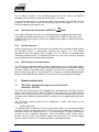
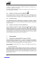
Le poste de soudage TIG est commandé à partir du panneau de commande REHM
représenté en figure 3.1 et figure 3.2.
0
2
4 6
8
10
sec
A
730 0641
5
20
40
60 80
120
140
150
170
100
0,5
5
10 15
20
25
sec
5
231
6 74
Figure 3.1 Panneau de commande TIGER 170
Figure 3.2 Panneau de commande TIGER 210
Le panneau de commande comprend les éléments suivants :
Sélecteur pour l’appareil d’amorçage HF
Temps de baisse de courant
Temps de post-émission de gaz
Lampes témoins de surchauffe et de marche
Bouton de sélection du courant de soudage
Sélecteur pour TIG, Électrode, booster d’électrode
Sélecteur de fonction TIG 2 temps, TIG 4 temps

17
3.1.2 Symboles et leur signification
Les symboles du panneau de commande signifient :
Le poste de soudage est réglé sur le soudage TIG. Le courant maximal est fixé
sur 170 A pour le TIGER 170 et sur 210 A pour le TIGER 210.
Le poste de soudage est réglé sur le soudage avec électrodes et la fonction
Protection coupe-circuit. Le courant maximal est fixé sur 140 A pour le TIGER
170 et sur 160 A pour le TIGER 210.
Le poste de soudage est réglé sur le soudage avec électrodes et la fonction
BOOSTER. Le courant maximal est fixé sur 150 A pour le TIGER 170 et sur
170 A pour le TIGER 210.
Le poste de soudage est en mode de soudage à 2 temps
Le poste de soudage est en mode de soudage à 4 temps
La haute fréquence (HF) est activée pour l’amorçage sans contact de l’arc
électrique en mode TIG.
La haute fréquence (HF) est coupée. L’amorçage Lift-Arc à cycles
automatiques est activé.
Réglage du temps de baisse de courant dans la plage entre 0,0 et 10,0
secondes.
Réglage du temps de post-émission de gaz dans la plage entre 0,5 et 25,0
secondes.
La tension à vide est appliquée à la torche ou au porte-électrode.
Quand la lampe témoin clignote, la surveillance interne est déclenchée. Le
poste est remis en service en coupant puis rétablissant le courant au
commutateur principal. Merci d’en informer le Service Clientèle REHM (RKS).
Témoin de température. La diode luminescente (jaune) s’allume lorsque la
température maximale autorisée du poste est dépassée. Tant que cette diode
est allumée, le courant de sortie est coupé. Après refroidissement du poste, la
diode s’éteint et le soudage peut être repris automatiquement. Quand le témoin
clignote, la surveillance interne est déclenchée. Le poste est remis en service
en coupant puis rétablissant le courant au commutateur principal. Merci d’en
informer le Service Clientèle REHM (RKS).
3.2 Marquage « + » sur la douille de courant de soudage
Le signe « + » indique le pôle positif de la source de courant de soudage. Dans le soudage
TIG, le câble de mise à la masse est connecté à cette douille.

18
F
3.3 Marquage « - » / symbole TIG sur la douille de courant de soudage
Le signe « - » indique le pôle négatif de la source de courant de soudage. Dans le soudage
TIG, la torche est connectée à cette douille.
4 Branchement au secteur
Le poste de soudage est muni d’une fiche de prise de courant de sécurité. Le poste
fonctionne sous un courant nominal de 16 A avec des coupe-circuit ou des disjoncteurs de
protection de canalisations. Le mode de service EIN (MARCHE) est indiqué par l’allumage
du commutateur principal placé au dos.
Lors de fréquentes (brèves et successives) activations et désactivations du TIGER, il peut
arriver que le poste commute en mode protection, dans lequel il ne peut s’amorcer et la
lampe témoin de marche verte s’allume et s’éteint. Dans ce cas, mettre le poste hors service
et attendre 2 minutes environ. Le poste peut alors être remis en service.
5 Installation
Lors de l’installation des postes, veiller à ce que les grilles d’aération ne soient pas
recouvertes et à ce que l’environnement soit conforme à la classe de protection IP23.
6 Modes de soudage
6.1 Soudage TIG
6.1.1 Principe du procédé de soudage TIG
Pour le soudage TIG, le poste met à disposition un courant pouvant atteindre 170 A / 210 A.
Dans cette fonction, la limitation du courant du secteur n’est pas activée. Étant donné que,
malgré un courant plus important, la puissance utile en mode TIG est inférieure à celle du
soudage avec électrodes, il ne faut pas s’attendre ici à un déclenchement de coupe-circuit.
Dans le procédé de soudage TIG, l’arc électrique se forme librement entre une électrode en
tungstène et la pièce d’œuvre. Le gaz protecteur est un gaz rare tel que l’argon, l’hélium ou
un mélange de ces deux gaz.
Le pôle négatif de la source d’énergie est sur l’électrode en tungstène, le pôle positif sur la
pièce d’œuvre. L’électrode conduit le courant et porte l’arc électrique (électrode
permanente). Le métal d’apport est appliquée sous forme de baguette tenue à la main ou
sous forme de fil par un appareil d’alimentation en fil froid séparé. L’électrode en tungstène
et le bain de fusion ainsi que l’extrémité en fusion du métal d’apport sont protégés de l’entrée
de l’oxygène de l’air par le gaz inerte protecteur qui s’échappe des buses disposées de
manière concentrique autour de l’électrode.
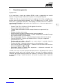
6.1.2 L’amorçage de l’arc électrique avec INTIG-Energy
Avec le mode INTIG-Energy (Intelligent Ignition Energy), le TIGER 170 / 210 maîtrise la
forme intelligente de commande d’énergie d’amorçage. La commande à processeur règle de
La pagina si sta caricando...
La pagina si sta caricando...
La pagina si sta caricando...
La pagina si sta caricando...
La pagina si sta caricando...
La pagina si sta caricando...
La pagina si sta caricando...
La pagina si sta caricando...
La pagina si sta caricando...
La pagina si sta caricando...
La pagina si sta caricando...
La pagina si sta caricando...
La pagina si sta caricando...
La pagina si sta caricando...
La pagina si sta caricando...
La pagina si sta caricando...
La pagina si sta caricando...
La pagina si sta caricando...
La pagina si sta caricando...
La pagina si sta caricando...
La pagina si sta caricando...
La pagina si sta caricando...
La pagina si sta caricando...
La pagina si sta caricando...
La pagina si sta caricando...
La pagina si sta caricando...
La pagina si sta caricando...
La pagina si sta caricando...
La pagina si sta caricando...
La pagina si sta caricando...
La pagina si sta caricando...
La pagina si sta caricando...
La pagina si sta caricando...
La pagina si sta caricando...
La pagina si sta caricando...
La pagina si sta caricando...
La pagina si sta caricando...
La pagina si sta caricando...
La pagina si sta caricando...
La pagina si sta caricando...
La pagina si sta caricando...
La pagina si sta caricando...
La pagina si sta caricando...
-
 1
1
-
 2
2
-
 3
3
-
 4
4
-
 5
5
-
 6
6
-
 7
7
-
 8
8
-
 9
9
-
 10
10
-
 11
11
-
 12
12
-
 13
13
-
 14
14
-
 15
15
-
 16
16
-
 17
17
-
 18
18
-
 19
19
-
 20
20
-
 21
21
-
 22
22
-
 23
23
-
 24
24
-
 25
25
-
 26
26
-
 27
27
-
 28
28
-
 29
29
-
 30
30
-
 31
31
-
 32
32
-
 33
33
-
 34
34
-
 35
35
-
 36
36
-
 37
37
-
 38
38
-
 39
39
-
 40
40
-
 41
41
-
 42
42
-
 43
43
-
 44
44
-
 45
45
-
 46
46
-
 47
47
-
 48
48
-
 49
49
-
 50
50
-
 51
51
-
 52
52
-
 53
53
-
 54
54
-
 55
55
-
 56
56
-
 57
57
-
 58
58
-
 59
59
-
 60
60
-
 61
61
-
 62
62
-
 63
63


REHM TIGER 170 Operating Instructions Manual
- Categoria
- Sistema di saldatura
- Tipo
- Operating Instructions Manual
in altre lingue
- English: REHM TIGER 170
- français: REHM TIGER 170
- español: REHM TIGER 170
Altri documenti
-
GYS NEOPULSE 320 C Manuale del proprietario
-
-
-
GYS WIRE FEEDER AIR/WATER NEOFEED-4W Manuale del proprietario
-
-
GYS TIG 220 AC/DC HF FV Manuale del proprietario
-
-
GYS PROTIG 200 DC HF Manuale del proprietario
-
-