IMG STAGELINE LR-1000F Manuale utente
- Categoria
- Altoparlanti
- Tipo
- Manuale utente
Questo manuale è adatto anche per

ELECTRONICS FOR SPECIALISTS ELECTRONICS FOR SPECIALISTS ELECTRONICS FOR SPECIALISTS ELECTRONICS FOR SPECIALISTS ELECTRONICS FOR SPECIALISTS ELECTRONICS
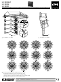
LR-1000SAT Bestellnummer 25.4700
LR-1000U Bestellnummer 25.4730
LR-1000F Bestellnummer 25.4720
MONACOR INTERNATIONAL GmbH & Co. KG • Zum Falsch 36 • 28307 Bremen • Germany
Copyright
©
by MONACOR INTERNATIONAL. All rights reserved.
A-1423.99.02.02.2020
PA- Lautsprecher und Montageteile
Diese Anleitung richtet sich an Installateure für
Beschallungsanlagen. Bitte lesen Sie die An-
leitung vor dem Betrieb gründlich durch und
heben Sie sie für ein späteres Nachlesen auf.
1 Einsatzmöglichkeiten
Die vier Lautsprecherboxen LR-1000SAT sind als
2-Wege-Systeme für Beschallungaufgaben mit
höchsten Ansprüchen konzipiert. Sie entspre-
chen der Mittelhochtoneinheit des Lautsprecher-
systems L-RAY/1000 und sind jeweils mit zwei
10-cm-Mitteltönern, einem Bändchen-Magneto-
staten als Hochtöner und einer darauf abge-
stimmten Frequenzweiche bestückt. Der Betrieb
sollte zusammen mit einem Bass-System (z. B.
LR-1000SUB) bei einer Trennfrequenz von 120 bis
200 Hz erfolgen.
Mithilfe des Montagerahmens LR-1000F las-
sen sich die Lautsprecherboxen aufhängen oder
über den Montagebügel LR-1000U auf ein Stativ
montieren. Dabei können die Winkel zwischen
den Lautsprecherboxen einzeln so eingestellt wer-
den, dass eine optimale Schallverteilung im Raum
erreicht wird.
2 Wichtige Hinweise
Die Lautsprecherboxen LR-1000SAT entsprechen
allen relevanten Richtlinien der EU und sind des-
halb mit gekennzeichnet.
•
Verwenden Sie die Lautsprecherboxen nur im
Innenbereich und schützen Sie sie vor Tropf-
und Spritzwasser, hoher Luftfeuchtigkeit und
Hitze (zulässige Einsatztemperatur 0 – 40 °C).
•
Verwenden Sie zum Reinigen nur ein trockenes,
weiches Tuch, auf keinen Fall Chemikalien oder
Wasser.
•
Werden die Lautsprecherboxen zweckentfrem-
det, falsch angeschlossen, nicht sicher montiert
oder nicht fachgerecht repariert, kann keine
Haftung für daraus resultierende Sach- oder
Personenschäden und keine Garantie für die
Lautsprecherboxen übernommen werden.
Sollen die Lautsprecherboxen endgültig
aus dem Betrieb genommen werden,
übergeben Sie sie zur umweltgerechten
Entsorgung einem örtlichen Recycling-
betrieb.
3 Montage
WARNUNG Nicht fachgerecht ausgeführte In-
stallationen, besonders bei über
Personen hängenden Systemen,
stellen eine potentielle Gefahr dar.
Darum darf die Installation nur von Fachperso-
nal mit Kenntnissen der gültigen Normen und
Sicherheitsvorschriften durchgeführt werden.
Die Installation, insbesondere die Stabilität der
Montageverbindungen, ist entsprechend regel-
mäßig zu kontrollieren.
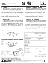
Zum Verbinden der vier Lautsprecherboxen:
1) Die vier Lautsprecherboxen mit je zwei Kugel-
sperrbolzen an der Vorderseite miteinander
verbinden (Abb. 1). Den Stift eines Bolzens
zum Entriegeln hineindrücken, den Bolzen bis
zum Anschlag durch die Bohrungen stecken
und den Stift wieder loslassen. Die Verbindung
immer kontrollieren: Der Bolzen darf sich ohne
Entriegeln nicht mehr herausziehen lassen.
2) Die Lautsprecherboxen rückseitig miteinander
verbinden. Für eine gleichmäßige Schallvertei-
lung kann eine gebogene Form des Lautspre-
chersystems sinnvoll sein. Zu diesem Zweck
sind die Winkel zwischen den Lautsprecherbo-
xen individuell einstellbar:
Wie in der unteren Detailansicht der Abbil-
dung 1 das Verbindungsglied (5) mit einer
Inbusschraube an der unteren Lautsprecherbox
befestigen. Das Verbindungsglied mit einem
Kugelsperrbolzen an der oberen Lautsprecher-
box befestigen. Dabei den Winkel zwischen
zwei Boxen durch die Wahl der passenden
Bohrungen festlegen.
3.1 Montage mit dem Rahmen LR-1000F
Wie in Abbildung 1 gezeigt, können die Laut-
sprecher mit dem Rahmen LR-1000F aufgehängt
(geflogen) werden.
1) Die vertikalen Montageschienen an den vor-
deren Kanten der oberen Lautsprecherbox auf
die beiden vorderen vom Rahmen abstehenden
Verbindungsstücke stecken und jeweils mit
einem Kugelsperrbolzen (2) befestigen.
2) Wie in der Abbildung gezeigt, die Rückseite der
oberen Lautsprecherbox und die Befestigungs-
laschen (3) an der Mittelstrebe des Rahmens
mit einer Inbusschraube, einem Kugelsperrbol-
zen und dem Verbindungsglied (4) verbinden.
3) Die vier Ringschrauben (1) in die Gewinde auf
der Oberseite des Rahmens fest einschrauben.
Den Rahmen an allen vier Ringschrauben sicher
aufhängen.
Der Rahmen LR-1000F kann auch dazu verwen-
det werden, die Basseinheit LR-1000SUB des
L-RAY/ 1000-Systems aufzustellen. In diesem Fall
anstelle der Ringschrauben die Gummifüße am
Rahmen festschrauben und den Rahmen auf
einen sicheren Untergrund stellen. Die vertikalen
Montageschienen an den Kanten der Basseinheit
auf die vier vom Rahmen hochstehenden Verbin-
dungsstücke stecken und mit vier Kugelsperrbol-
zen befestigen.
3.2 Stativmontage mit dem
HaltebügelLR-1000U
Über den Haltebügel LR-1000U können die Laut-
sprecherboxen auf ein Standard-Lautsprecher-
stativ mit 35 mm Rohrdurchmesser ge steckt
werden (z. B. aus der PAST-Serie) oder über ein
Distanzrohr auf einem Subwoofer befestigt wer-
den (z. B. mit KM-21367 auf dem LR-1000SUB).
1) An der zweiten Lautsprecherbox von unten
die fünf seitlichen Abdeckschrauben (Inbus)
entfernen.
2) Die Lautsprecherbox auf beiden Seiten am Hal-
tebügel festschrauben (
☞
Abb. 2).
3) Den Haltebügel mit den Lautsprecherboxen auf
das Stativ oder das Distanzrohr stecken und mit
der Feststellschraube (7) fixieren.
4) Zum Ausrichten auf beiden Seiten die obere
Schraube (6) lösen, die Boxen wie gewünscht
neigen (±15°) und die Schrauben wieder fest-
drehen.
4 Anschluss
Den Anschluss oder die Änderung des bestehen-
den Anschlusses nur bei ausgeschaltetem Verstär-
ker durchführen.
1) Den Verstärkerausgang mit einer der beiden
Buchsen auf der Rückseite der ersten Lautspre-
cherbox verbinden. Einen Lautsprecherstecker
nach dem Einstecken in die Buchse nach rechts
drehen, bis er einrastet. Zum späteren Heraus-
ziehen den Sicherungsriegel am Stecker zu-
rückziehen und den Stecker nach links drehen.
2) An die andere Buchse die nächste Lautspre-
cherbox anschließen. Beide Buchsen sind pa-
rallel geschaltet.
3) Auf die gleiche Weise die dritte Lautsprecher-
box an die zweite und die vierte an die dritte
anschließen.
Jede Lautsprecherbox hat eine Nennimpe-
danz von 16 Ω, sodass bei Parallelschaltung
aller vier Boxen der Verstärker mit einer Ge-
samtimpedanz von 4 Ω belastet wird.
5 Technische Daten
LR-1000SAT
Lautsprecherbestückung
Mitteltöner: . . . . . . . . . 8 × SP-4 / 60PRO
Hochtöner: . . . . . . . . . . 4 × RBT-1000
Impedanz:
. . . . . . . . . . . . 16 Ω
je Lautsprecherbox
Belastbarkeit (gesamt)
nominal (RMS): . . . . . . . 350 W
maximal: . . . . . . . . . . . 700 W
Kennschalldruck
(1 W/ 1 m): . . . . . . . . . . . . 96 dB
Max. Nennschalldruck: . . 121 dB
Frequenzbereich: . . . . . . 120 – 25 000 Hz
Richtcharakteristik: . . . . .
☞
Abbildung 3 und 4
Anschlüsse:
. . . . . . . . . . . Speakon
®
Einsatztemperatur: . . . . . 0 – 40 °C
Abmessungen: . . . . . . . . 492 × 532 × 250 mm
Gewicht: . . . . . . . . . . . . . 20 kg
LR-1000F
Abmessungen: . . . . . . . . 468 × 608 mm
Gewicht: . . . . . . . . . . . . . 12 kg
Belastbarkeit: . . . . . . . . . 4 × LR-1000SAT
+ 4 × LR-1000SUB
LR-1000U
Abmessungen: . . . . . . . . 500 × 310 × 100 mm
Gewicht: . . . . . . . . . . . . . 3,1 kg
Belastbarkeit: . . . . . . . . . 1 × LR-1000SAT
Änderungen vorbehalten.
Deutsch

ELECTRONICS FOR SPECIALISTS ELECTRONICS FOR SPECIALISTS ELECTRONICS FOR SPECIALISTS ELECTRONICS FOR SPECIALISTS ELECTRONICS FOR SPECIALISTS ELECTRONICS
MONACOR INTERNATIONAL GmbH & Co. KG • Zum Falsch 36 • 28307 Bremen • Germany
Copyright
©
by MONACOR INTERNATIONAL. All rights reserved.
A-1423.99.02.02.2020
LR-1000SAT Order No. 25.4700
LR-1000U Order No. 25.4730
LR-1000F Order No. 25.4720
PA Speaker Systems
andMountingParts
These instructions are intended for installers
of PA systems. Please read these instructions
carefully prior to operation and keep them
for later reference.
1 Applications
The four speaker systems LR-1000SAT are de-
signed as 2-way systems for high-requirement
PA applications. They correspond to the mid-
high range component of the speaker system
L-RAY/1000 and are each equipped with two
10 cm midrange speakers, a magnetostatic ribbon
as a tweeter and a matching crossover network.
The speaker systems should be operated together
with a bass system (e. g. LR-1000SUB) at a cross-
over frequency of 120 to 200 Hz.
The speaker systems can either be suspended
by means of the mounting frame LR-1000F or
they can be mounted onto a stand by means
of the mounting bracket LR-1000U. The angles
between the speaker systems can be individually
adjusted so that an optimum sound distribution is
obtained in the room.
2 Important Notes
The speaker systems LR-1000SAT correspond to
all relevant directives of the EU and are therefore
marked with .
•
The speaker systems are suitable for indoor use
only. Protect them against dripping water and
splash water, high air humidity and heat (ad-
missible ambient temperature range 0 – 40 °C).
•
For cleaning only use a dry, soft cloth, never use
chemicals or water.
•
No guarantee claims for the speaker systems
and no liability for any resulting personal dam-
age or material damage will be accepted if the
speaker systems are used for other purposes
than originally intended, if they are not correctly
connected, not safely mounted, or if they are
not repaired in an expert way.
If the speaker systems are to be put out
of operation definitively, take them to a
local recycling plant for a disposal which
is not harmful to the environment.
3 Installation
WARNING Installations which are not made
in an expert way are a hazard, es-
pecially if systems are suspended
(flown) above persons. Therefore,
the installation must only be made by expert
personnel familiar with the valid stand ards and
safety regulations.
The installation, especially the stability of the
mounting connections, must be checked at
regular intervals.
To connect the four speaker systems:
1) Connect the four speaker systems with each
other, using the two ball lock bolts that are pro-
vided on the front side (fig.1) of each speaker
system. Press the pin to unlock the bolt, put the
bolt through the drill holes up to the stop and
then release the pin. Always check the con-
nection and make sure that the bolt cannot be
removed without unlocking.
2) Connect the speaker systems with each other
on the rear side. A curved form of the speaker
system may be useful to achieve an even sound
distribution. For this purpose, the angles be-
tween the speaker systems can be adjusted
individually:
As shown in the lower detailed view of fig.1,
attach the connecting plate (5) to the lower
speaker system using a hexagon socket screw.
Attach the connecting plate to the upper
speaker system using a ball lock bolt; select the
appropriate drill holes to set the desired angle
between the two systems.
3.1 Mounting with the frame LR-1000F
As shown in fig. 1, the speakers can be suspended
(flown) with the frame LR-1000F.
1) Place the vertical mounting rails at the front
edges of the upper speaker system onto the
two front connecting plates that stick out of
the frame and fix each of the mounting rails
with a ball lock bolt (2).
2) As shown in the figure, connect the rear side
of the upper speaker system and the fixing
straps (3) at the centre strut of the frame with
a hexagon socket screw, a ball lock bolt and
the connecting plate (4).
3) Tightly screw the four ring bolts (1) into the
threads on the upper side of the frame. Then
safely suspend the frame by means of the four
ring bolts.
The frame LR-1000F can also be used to set up the
bass unit LR-1000SUB of the L-RAY/1000 system:
Instead of the ring bolts, tightly screw the rubber
feet to the frame and place the frame on a safe
ground. Place the vertical mounting rails at the
edges of the bass unit onto the four connecting
plates that stick out of the frame and then fix
them with four ball lock bolts.
3.2 Mounting the speaker systems with the
supporting bracket LR-1000U onto a stand
The supporting bracket LR-1000U allows the
speaker systems to be placed onto a standard
speaker stand with a tube diameter of 35 mm
(e. g. from the PAST series) or onto a subwoofer
by means of a distance rod (e. g. by means of the
KM-21367 on the LR-1000SUB).
1) Remove the five lateral cover screws (hexagon
socket screws) from the second speaker system
from below.
2) Tightly screw the speaker system on both sides
to the supporting bracket (
☞
fig. 2).
3) Place the supporting bracket with the speaker
systems onto the stand or the distance rod and
fix it with the setscrew (7).
4) For alignment, release the upper screw (6) on
both sides, incline the systems as desired (±15°)
and retighten the screws.
4 Connection
Only establish or change a connection with the
amplifier switched off.
1) Connect the amplifier output to one of the
two jacks on the rear side of the first speaker
system. After inserting a speaker plug into the
jack, turn it clockwise until it engages. To re-
move the speaker plug, pull back the latch lock
of the plug and turn the plug counter-clock-
wise.
2) Connect the next speaker system to the other
jack. Both jacks are connected in parallel.
3) Proceed in the same way to connect the third
speaker system to the second and the fourth
speaker system to the third.
Each speaker system has a rated impedance
of 16 Ω, that is, the amplifier will be loaded
with a total impedance of 4 Ω when the four
systems are connected in parallel.
5 Specifications
LR-1000SAT
Speaker equipment
Midrange speakers: . . . 8 × SP-4 / 60PRO
Tweeters: . . . . . . . . . . . 4 × RBT-1000
Impedance:
. . . . . . . . . . . 16 Ω for each speaker
system
Power rating (total)
Nominal (RMS): . . . . . . 350 W
Maximum: . . . . . . . . . . 700 W
SPL (1 W/ 1 m): . . . . . . . . . 96 dB
Max. SPL: . . . . . . . . . . . . 121 dB
Frequency range: . . . . . . 120 – 25 000 Hz
Directivity: . . . . . . . . . . . .
☞
figs. 3 and 4
Connections:
. . . . . . . . . Speakon
®
Ambient temperature: . . 0 – 40 °C
Dimensions: . . . . . . . . . . 492 × 532 × 250 mm
Weight: . . . . . . . . . . . . . 20 kg
LR-1000F
Dimensions: . . . . . . . . . . 468 × 608 mm
Weight: . . . . . . . . . . . . . 12 kg
Loading capacity: . . . . . . 4 × LR-1000SAT
+ 4 × LR-1000SUB
LR-1000U
Dimensions: . . . . . . . . . . 500 × 310 × 100 mm
Weight: . . . . . . . . . . . . . 3.1 kg
Loading capacity: . . . . . . 1 × LR-1000SAT
Subject to technical modification.
English

ELECTRONICS FOR SPECIALISTS ELECTRONICS FOR SPECIALISTS ELECTRONICS FOR SPECIALISTS ELECTRONICS FOR SPECIALISTS ELECTRONICS FOR SPECIALISTS ELECTRONICS
MONACOR INTERNATIONAL GmbH & Co. KG • Zum Falsch 36 • 28307 Bremen • Germany
Copyright
©
by MONACOR INTERNATIONAL. All rights reserved.
A-1423.99.02.02.2020
LR-1000SAT Réf. num. 25.4700
LR-1000U Réf. num. 25.4730
LR-1000F Réf. num. 25.4720
Enceinte professionnelle
etélémentsde montage
Cette notice s’adresse aux installateurs
d’installations de sonorisation. Veuillez lire
la présente notice avant le fonctionnement
et conservez-la pour pouvoir vous y reporter
ultérieurement.
1 Possibilités d’utilisation
Les quatre enceintes LR-1000SAT sont conçues
comme des systèmes 2 voies pour sonorisation
professionnelles exigeantes. Elles correspondent
à l’unité médium aigu du système L-RAY/ 1000 et
sont dotées respectivement de deux haut-parleurs
de médium 10 cm, d’un ribbon magnétostatique
et d’un filtre de fréquences. Le fonctionnement ne
devrait s’effectuer qu’avec un système de grave
(p. ex. LR-1000SUB) pour une fréquence de cou-
pure de 120 à 200 Hz.
Avec le cadre de montage LR-1000F, on peut
suspendre les enceintes ou via l’étrier de montage
LR-1000U, les monter sur un pied. Les angles
entre les enceintes peuvent être réglés de telle
sorte qu’on obtienne une répartition optimale du
son dans la pièce.
2 Conseils importants
Les enceintes LR-1000SAT répondent à toutes les
directives nécessaires de l’union européenne et
portent donc le symbole .
•
Les enceintes ne sont conçues que pour une uti-
lisation en intérieur. Protégez-les de tout type de
projections d’eau, des éclaboussures et projec-
tions d’eau, d’une humidité élevée de l’air et de
la chaleur (plage de température de fonctionne-
ment autorisée: 0 à 40 °C).
•
Pour le nettoyage, utilisez un chiffon sec et
doux, en aucun cas de produits chimiques ou
d’eau.
•
Nous déclinons toute responsabilité en cas de
dommages matériels ou corporels résultants si
les enceintes sont utilisées dans un but autre
que celui pour lequel elles ont été conçues,
si elles ne sont pas correctement branchées ou
montées ou si elles ne sont pas réparées par une
personne habilitée, en outre, la garantie devien-
drait caduque.
Lorsque les enceintes sont définitive-
ment retirées du service, vous devez les
déposer dans une usine de recyclage
adaptée pour contribuer à leur élimina-
tion non polluante.
CARTONS ET EMBALLAGE
PAPIER À TRIER
3 Montage
AVERTISSEMENT Toute installation non réalisée
par un professionnel, en par-
ticulier pour des systèmes sus-
pendus au-dessus du public, re-
présente un danger potentiel.
C’est pourquoi l’installation doit impérativement
être effectuée par un personnel qualifié ayant
des connaissances des normes en vigueur, des
prescriptions de sécurité.
L’installation, la stabilité des liaisons de mon-
tage doivent en conséquence être régulièrement
vérifiées.
Pour relier les quatre enceintes:
1) Reliez les quatre enceintes avec respectivement
deux axes de blocage à billes sur la face avant
(schéma 1) de chaque enceinte. Pour déver-
rouiller l’axe de blocage, appuyez sur le pin,
mettez l’axe de blocage à billes jusqu’à la butée
via les perçages et relâchez le pin. Vérifiez tou-
jours la connexion: l’axe de blocage ne doit pas
pouvoir être retiré sans être déverrouillé.
2) Reliez les enceintes ensemble sur la face arrière.
Pour une répartition régulière du son, il est
intéressant de donner une forme courbe au
système. Les angles entre les enceintes sont
donc réglables individuellement:
Comme indiqué sur la vue de détail inférieure
du schéma 1, fixez l’élément de liaison (5)
avec une vis à six pans creux sur l’enceinte
inférieure. Fixez l’élément de liaison avec un
axe de blocage à billes à l’enceinte supérieure.
Définissez l’angle entre les deux enceintes en
sélectionnant les perçages correspondants.
3.1 Montage avec le cadre LR-1000F
Comme indiqué sur le schéma 1, on peut sus-
pendre les enceintes avec le cadre LR-1000F.
1) Placez les rails verticaux de montage situés sur
les arêtes avant de l’enceinte supérieure sur les
deux éléments de liaison avant sortant du cadre
et fixez-les avec un axe de blocage à bille (2) sur
les rails de montage.
2) Comme indiqué sur le schéma, reliez la face ar-
rière de l’enceinte supérieure et les languettes
de fixation (3) sur la partie médiane du cadre
avec une vis à six pans creux, un axe de blocage
à billes et un élément de liaison (4).
3) Vissez les quatre vis à œillet (1) dans les file-
tages sur la face supérieure du cadre. Suspen-
dez le cadre via les quatre vis à œillet.
Le cadre LR-1000F peut également être utilisé
pour positionner l’unité de grave LR-1000SUB du
système L-RAY/ 1000. Dans ce cas, et à la place
des vis à œillet, vissez les pieds caoutchouc sur le
cadre et placez le cadre sur un support sûr. Mettez
les rails de montage verticaux sur les arêtes de
l’unité de grave sur les quatre éléments de liai-
son sortant du cadre et fixez avec quatre axes de
blocage à billes.
3.2 Montage sur pied avec l’étrier LR-1000U
On peut, via l’étrier LR-1000U, placer les en-
ceintes sur un pied standard avec diamètre de
tube 35 mm (p. ex. dans la série PAST) ou les fixer
sur un subwoofer via un tube intermédiaire (par
exemple KM-21367 sur le LR-1000SUB).
1) Retirez les cinq vis latérales (vis à six pans creux)
de la seconde enceinte en partant du bas.
2) Vissez l’enceinte sur les deux côtés sur l’étrier
(
☞
schéma2).
3) Placez l’étrier avec les enceintes sur le pied ou
le tube intermédiaire et fixez avec la vis (7).
4) Pour orienter, desserrez sur les deux côtés la
vis supérieure (6), inclinez les enceintes comme
souhaité (±15°) et revissez.
4 Branchement
L’amplificateur doit impérativement être éteint
lors des branchements ou si vous modifiez les
branchements existants.
1) Reliez la sortie amplificateur à une des deux
prises sur la face arrière de la première en-
ceinte. Une fois dans la prise, tournez vers la
droite une fiche haut-parleur jusqu’à ce qu’elle
s’enclenche. Pour pouvoir ultérieurement la
retirer, tirez le levier de sécurité sur la fiche et
tournez la fiche vers la gauche.
2) Reliez l’enceinte suivante à l’autre prise. Les
deux prises sont branchées en parallèle.
3) De la même manière, reliez la troisième en-
ceinte à la deuxième et la quatrième à la troi-
sième.
Chaque enceinte a une impédance nomi-
nale de 16 Ω afin que l’amplificateur reçoive
une impédance totale de 4 Ω si les quatre en-
ceintes sont branchées en parallèle.
5 Caractéristiques techniques
LR-1000SAT
Haut-parleurs
Médiums: . . . . . . . . . . 8 × SP-4 / 60PRO
Aigus: . . . . . . . . . . . . . 4 × RBT-1000
Impédance:
. . . . . . . . . . 16 Ω par enceinte
Puissance (totale)
Nominale (RMS): . . . . . 350 W
Maximale: . . . . . . . . . . 700 W
Pression sonore
(1 W/ 1 m): . . . . . . . . . . . 96 dB
Pression sonore
nominale max.:
. . . . . . . 121 dB
Bande passante: . . . . . . . 120 – 25 000 Hz
Caractéristique
directivité:
. . . . . . . . . . .
☞
schéma 3 et 4
Branchements:
. . . . . . . . Speakon
®
Température fonc.: . . . . . 0 – 40 °C
Dimensions: . . . . . . . . . . 492 × 532 × 250 mm
Poids: . . . . . . . . . . . . . . . 20 kg
LR-1000F
Dimensions: . . . . . . . . . . 468 × 608 mm
Poids: . . . . . . . . . . . . . . . 12 kg
Charge admissible: . . . . . 4 × LR-1000SAT
+ 4 × LR-1000SUB
LR-1000U
Dimensions: . . . . . . . . . . 500 × 310 × 100 mm
Poids: . . . . . . . . . . . . . . . 3,1 kg
Charge admissible: . . . . . 1 × LR-1000SAT
Tout droit de modification réservé.
Français

ELECTRONICS FOR SPECIALISTS ELECTRONICS FOR SPECIALISTS ELECTRONICS FOR SPECIALISTS ELECTRONICS FOR SPECIALISTS ELECTRONICS FOR SPECIALISTS ELECTRONICS
MONACOR INTERNATIONAL GmbH & Co. KG • Zum Falsch 36 • 28307 Bremen • Germany
Copyright
©
by MONACOR INTERNATIONAL. All rights reserved.
A-1423.99.02.02.2020
LR-1000SAT Codice 25.4700
LR-1000U Codice 25.4730
LR-1000F Codice 25.4720
Diffusori PA e pezzi di montaggio
Queste istruzioni sono rivolte agli installatori
di impianti di sonorizzazione. Vi preghiamo
di leggerle attentamente prima della messa
in funzione e di conservarle per un uso fu-
turo.
1 Possibilità d’impiego
Le quattro casse acustiche LR-1000SAT sono state
realizzate come sistemi a 2 vie per sonorizzazione
esigente. Corrispondono all’unità midrange /
tweeter del sistema di diffusori L-RAY/ 1000 e
sono equipaggiate ognuna con due midrange
di 10 cm, con un magnetostato a nastro come
tweeter e con un filtro di frequenza con relativa
regolazione. L’impiego dovrebbe essere fatto
insieme ad un woofer (p. es. LR-1000SUB) con
frequenza di taglio fra 120 e 200 Hz.
Con l’aiuto del telaio di montaggio LR-1000F,
le casse possono essere sospese oppure possono
essere montate su uno stativo tramite la staffa di
montaggio LR-1000U. In questo caso, gli angoli
possono essere regolati singolarmente in modo
tale da ottenere una distribuzione ottimale del
suono nell’ambiente.
2 Avvertenze importanti per l’uso
Le casse acustiche LR-1000SAT sono conformi a
tutte le direttive rilevanti dell’UE e pertanto por-
tano la sigla .
•
Usare le casse solo all’interno di locali e pro-
teggerle dall’acqua gocciolante e dagli spruzzi
d’acqua, da alta umidità dell’aria e dal calore
(temperatura d’impiego ammessa fra 0 e 40 °C).
•
Per la pulizia usare solo un panno morbido,
asciutto; non impiegare in nessun caso acqua
o prodotti chimici.
•
Nel caso d’uso improprio, di collegamenti sba-
gliati, di montaggio insicuro o di riparazione
non a regola d’arte delle casse acustiche, non
si assume nessuna responsabilità per eventuali
danni consequenziali a persone o a cose e non
si assume nessuna garanzia per le casse.
Se si desidera eliminare le casse defi-
nitivamente, consegnarle per lo smal-
timento ad un’istituzione locale per il
riciclaggio.
3 Montaggio
AVVERTIMENTO Le installazioni non eseguite a
regola d’arte, specialmente in
caso di sistemi sospesi sopra
delle persone, costituiscono un
pericolo potenziale. Perciò, l’installazione deve
essere fatta solo da persone qualificate che
conoscono le relative disposizioni e norme di
sicurezza.
L’installazione, in modo particolare la stabilità
dei collegamenti nel montaggio, deve essere
controllata regolarmente.
Per collegare le quattro casse:
1) Collegare le quattro casse sul lato anteriore per
mezzo di due perni di bloccaggio a sfera per
ogni cassa (Fig.1). Spingere indentro la spina
di un perno per sganciarlo, inserire il perno at-
traverso i fori fino all’arresto e lasciare la spina.
Tutte le volte controllare il collegamento: il
perno non deve essere più sfilabile senza es-
sere sganciato.
2) Collegare le casse sui lati posteriori. Per una
distribuzione regolare del suono può essere op-
portuna una forma curvata del sistema. Perciò,
gli angoli fra le casse sono regolabili individual-
mente:
Come si vede nella parte bassa di figura 1,
fissare il giunto (5) con la cassa inferiore per
messo di una vite a brugola. Fissare il giunto
alla cassa superiore per mezzo di un perno di
bloccaggio a sfera, determinando l’angolo fra
le due casse scegliendo i fori adatti.
3.1 Montaggio con il telaio LR-1000F
Come illustra la figura 1, le casse possono essere
montate in modo sospeso per mezzo del telaio
LR-1000F.
1) Ai bordi anteriori della cassa in alto, inserire le
guide verticali di montaggio sui due giunti an-
teriori, distaccati dal telaio, e fissarle ognuna
con un perno di bloccaggio a sfera (2).
2) Come illustra la figura, collegare il lato poste-
riore della cassa in alto nonché le linguette di
fissaggio (3) con il montante centrale del telaio,
servendosi di una vite a brugola, di un perno di
bloccaggio a sfera e del giunto (4).
3) Avvitare bene le quattro viti ad anello (1) nelle
filettature sul lato superiore del telaio. Appen-
dere bene il telaio alle quattro viti ad anello.
Il telaio LR-1000F può servire anche per sis temare
il woofer LR-1000SUB del sistema L-RAY/ 1000. In
questo caso, al posto delle viti ad anello avvitare i
piedini di gomma sul telaio e posizionare il telaio
su una base sicura. Inserire le guide verticali di
montaggio sui bordi del woofer sui quattro giunti
che si staccano dal telaio e fissarle con quattro
perni di bloccaggio a sfera.
3.2 Montaggio su uno stativo tramite
la staffa LR-1000U
Tramite la staffa LR-1000U, le casse possono es-
sere inserite su uno stativo standard per altopar-
lanti con diametro del tubo di 35 mm (p. es. della
serie PAST-Serie) oppure possono essere fissate
tramite un tubo distanziatore su un subwoofer
(p. es. con KM-21367 sul LR-1000SUB).
1) Sulla seconda cassa, dal basso, togliere le cin-
que viti laterali di copertura (brugole).
2) Avvitare la cassa ai due lati sulla staffa
(
☞
Fig.2).
3) Inserire la staffa con le casse sullo stativo o sul
tubo distanziatore e fissarla con la vite di bloc-
caggio (7).
4) Per orientare le casse, allentare sui due lati la
vite superiore (6), inclinare le casse come desi-
derato (±15°) e stringere nuovamente le viti.
4 Connessione
Eseguire la connessione o una modifica della con-
nessione esistente solo con l’amplificatore spento.
1) Collegare l’uscita dell’amplificatore con una
delle due prese sul lato posteriore della prima
cassa. Dopo l’inserimento nella presa, girare a
destra un connettore dell’altoparlante fino allo
scatto. Per staccarlo successivamente, tirare
indietro la leva di sicurezza sul connettore e
girare il connettore a sinistra.
2) Collegare la cassa successiva con l’altra presa.
Entrambe le prese sono collegate in parallelo.
3) Nello stesso modo, collegare la terza cassa con
la seconda e la quarta con la terza.
Ogni cassa acustica ha un’impedenza no-
minale di 16 Ω, il ché significa che in caso di
collegamento in parallelo di tutte e quattro le
casse, l’amplificatore è esposto ad una impe-
denza globale di 4 Ω.
5 Dati tecnici
LR-1000SAT
Altoparlanti
Midrange: . . . . . . . . . . 8 × SP-4 / 60PRO
Tweeter: . . . . . . . . . . . . 4 × RBT-1000
Impedenza:
. . . . . . . . . . . 16 Ω per ogni cassa
Potenza (globale)
nominale (RMS): . . . . . . 350 W
massimo: . . . . . . . . . . . 700 W
Pressione sonora nom.le
(1 W/ 1 m): . . . . . . . . . . . . 96 dB
Press. son. nom. le max: . 121 dB
Gamma di frequenze: . . . 120 – 25 000 Hz
Caratteristica direzionale:
☞
Figure 3 e 4
Contatti:
. . . . . . . . . . . . . Speakon
®
Temperatura d’esercizio: . 0 – 40 °C
Dimensioni: . . . . . . . . . . . 492 × 532 × 250 mm
Peso: . . . . . . . . . . . . . . . . 20 kg
LR-1000F
Dimensioni: . . . . . . . . . . . 468 × 608 mm
Peso: . . . . . . . . . . . . . . . . 12 kg
Portata: . . . . . . . . . . . . . . 4 × LR-1000SAT
+ 4 × LR-1000SUB
LR-1000U
Dimensioni: . . . . . . . . . . . 500 × 310 × 100 mm
Peso: . . . . . . . . . . . . . . . . 3,1 kg
Portata: . . . . . . . . . . . . . . 1 × LR-1000SAT
Con riserva di modifiche tecniche.
Italiano

ELECTRONICS FOR SPECIALISTS ELECTRONICS FOR SPECIALISTS ELECTRONICS FOR SPECIALISTS ELECTRONICS FOR SPECIALISTS ELECTRONICS FOR SPECIALISTS ELECTRONICS
MONACOR INTERNATIONAL GmbH & Co. KG • Zum Falsch 36 • 28307 Bremen • Germany
Copyright
©
by MONACOR INTERNATIONAL. All rights reserved.
A-1423.99.02.02.2020
LR-1000SAT Ref. Núm. 25.4700
LR-1000U Ref. Núm. 25.4730
LR-1000F Ref. Núm. 25.4720
Recintos de Megafonía
yComponentes de Montaje
Estas instrucciones van dirigidas a instala-
dores de sistemas de megafonía. Lea aten-
tamente estas instrucciones antes de utilizar
el aparato y guárdelas para usos posteriores.
1 Aplicaciones
Los cuatro recintos LR-1000SAT están diseñados
como sistemas de 2 vías para megafonía de gran-
des requisitos. Corresponden al componente del
rango de medios-agudos del recinto L-RAY/ 1000
y están equipados con dos altavoces de medios
de 10 cm, una cinta magnetostática como tweeter
y el filtro crossover correspondiente. Los recintos
deberían utilizarse junto con un sistema de graves
(p. ej. LR-1000SUB) con una frecuencia crossover
de 120 a 200 Hz.
Los recintos se pueden suspender mediante
el marco de montaje LR-1000F o se pueden
montar en un pie mediante el soporte de mon-
taje LR-1000U. Los ángulos entre los recintos se
pueden ajustar individualmente de modo que
obtenga una distribución de sonido óptima en la
sala.
2 Notas Importantes
Los recintos LR-1000SAT cumplen con todas las
directivas relevantes de la UE y por lo tanto están
marcados con el símbolo .
•
Los recintos están adecuados sólo para utilizar-
los en interiores. Protéjalos de goteos y salpica-
duras, elevada humedad del aire y calor (tempe-
ratura ambiente admisible: 0 – 40 ºC).
•
Utilice sólo un paño suave y seco para la lim-
pieza, no utilice nunca ni productos químicos
ni agua.
•
No podrá reclamarse garantía o responsabilidad
alguna por cualquier daño personal o material
resultante si los recintos se utilizan para otros
fines diferentes a los originalmente concebidos,
si no se conectan correctamente, no se montan
con seguridad o si no los repara un experto.
Si va a poner los recintos fuera de servicio
definitivamente, llévelos a la planta de
reciclaje más cercana para que su elimi-
nación no perjudique el medioambiente.
3 Instalación
ADVERTENCIA Las instalaciones no realizadas
por un experto representan un
peligro potencial, especialmente
si los sistemas están suspendidos
(flotando) sobre personas. Por lo tanto, solo
el personal cualificado con conocimientos
sobre las normativas válidas y las regulacio-
nes de seguridad puede realizar la instalación.
La instalación, especialmente la estabilidad de
las conexiones de montaje, tienen que compro-
barse en intervalos regulares.
Para conectar los cuatro recintos:
1) Conecte los cuatro recintos entre sí, utilizando
los dos pernos de bola que se entregan en la
parte frontal (fig. 1) de cada recinto. Presione
la clavija para desbloquear el perno, coloque el
perno a través de los agujeros hasta el tope y
luego libere la clavija. Compruebe siempre la
conexión y asegúrese de que el perno no se
puede extraer sin desbloquearlo.
2) Conecte los recintos entre sí por la parte poste-
rior. La forma curvada del recinto puede ser útil
para conseguir una distribución uniforme del
sonido. Para ello, se pueden ajustar individual-
mente los ángulos entre los recintos:
Como se muestra en la imagen inferior deta-
llada de la fig. 1, hay que fijar la placa de cone-
xión (5) al recinto inferior utilizando un tornillo
de cabeza hexagonal. Fije la placa de conexión
a la parte superior del recinto utilizando un
perno de bola, seleccione los agujeros adecua-
dos para ajustar el ángulo deseado entre los
dos sistemas.
3.1 Montaje con el marco LR-1000F
Como se muestra en la fig. 1, los altavoces se pue-
den suspender (flotantes) con el marco LR-1000F.
1) Coloque los raíles de montaje verticales en los
perfiles frontales del recinto superior encima de
las dos placas frontales de conexión que sobre-
salen del marco y fije cada uno de los raíles de
montaje con un perno de bola (2).
2) Como se muestra en la figura, conecte la parte
posterior del recinto superior y las tiras de fija-
ción (3) en el puntal central del marco con un
tornillo de cabeza hexagonal, un perno de bola
y la placa de conexión (4).
3) Enrosque con firmeza los cuatro pernos de
anilla (1) en las roscas de la parte superior
del marco. Luego suspenda con seguridad el
marco mediante los cuatro pernos de anilla.
El marco LR-1000F también se puede utilizar
para ajustar el grave LR-1000SUB del sistema
L-RAY/ 1000: En lugar de los pernos de anilla, en-
rosque con firmeza los pies de caucho al marco y
fije el marco en un lugar seguro del suelo. Colo-
que los raíles de montaje vertical en los perfiles
de la unidad de graves en las cuatro placas de
conexión que sobresalen del marco y luego fíjelos
con cuatro pernos de bola.
3.2 Montaje de los recintos con el soporte
demontaje LR-1000U en un pie
El soporte de montaje LR-1000U permite colocar
los recintos en un pie de recinto con un diáme-
tro de tubo de 35 mm (p. ej. de la gama PAST)
o encima de un subwoofer mediante un tubo
separador (p. ej. mediante el KM-21367 encima
del LR-1000SUB).
1) Extraiga los cinco tornillos de tapa laterales
(tornillos de cabeza hexagonal) del segundo
recinto desde abajo.
2) Atornille con firmeza el recinto por ambos
lados al soporte de apoyo (
☞
fig.2).
3) Coloque el soporte de apoyo con los recintos
encima del pie o del tubo separador y fíjelo con
el tornillo de fijación (7).
4) Para el alineamiento, afloje el tornillo superior
(6) de ambos lados, incline los recintos como
quiera (±15°) y apriete los tornillos de nuevo.
4 Conexión
Establezca o cambie una conexión sólo con el am-
plificador desconectado.
1) Conecte la salida de amplificador a una de las
dos tomas de la parte posterior del primer re-
cinto. Después de insertar un conector de alta-
voz en la toma, gírelo en sentido horario hasta
que encaje. Para extraer el conector de altavoz,
estire de la pestaña de bloqueo del conector y
gírelo en sentido horario inverso.
2) Conecte el recinto siguiente a la otra toma.
Ambas tomas se conectarán en paralelo.
3) Proceda del mismo modo para conectar el
tercer recinto al segundo y el cuarto recinto al
tercero.
Cada recinto tiene una impedancia de 16 Ω,
lo que significa que el amplificador se cargará
con una impedancia total de 4 Ω cuando se
hayan conectado los cuatro sistemas en para-
lelo.
5 Especificaciones
LR-1000SAT
Equipamiento del recinto
Altavoces de medios: . . 8 × SP-4/60PRO
Tweeters: . . . . . . . . . . . 4 × RBT-1000
Impedancia:
. . . . . . . . . . 16 Ω por recinto
Potencia (total)
Nominal (RMS): . . . . . . 350 W
Máxima: . . . . . . . . . . . . 700 W
SPL (1 W/ 1 m): . . . . . . . . . 96 dB
Máx. SPL:
. . . . . . . . . . . . 121 dB
Rango de frecuencias: . . . 120 – 25 000 Hz
Directividad: . . . . . . . . . .
☞
Figuras 3 y 4
Conexiones:
. . . . . . . . . . Speakon
®
Temperatura
ambiente: . . 0 – 40 °C
Dimensiones: . . . . . . . . . 492 × 532 × 250 mm
Peso: . . . . . . . . . . . . . . . . 20 kg
LR-1000F
Dimensiones: . . . . . . . . . 468 × 608 mm
Peso: . . . . . . . . . . . . . . . . 12 kg
Capacidad de carga: . . . . 4 × LR-1000SAT
+ 4 × LR-1000SUB
LR-1000U
Dimensiones: . . . . . . . . . 500 × 310 × 100 mm
Peso: . . . . . . . . . . . . . . . . 3,1 kg
Capacidad de carga: . . . . 1 × LR-1000SAT
Sujeto a modificaciones técnicas.
Español

ELECTRONICS FOR SPECIALISTS ELECTRONICS FOR SPECIALISTS ELECTRONICS FOR SPECIALISTS ELECTRONICS FOR SPECIALISTS ELECTRONICS FOR SPECIALISTS ELECTRONICS
MONACOR INTERNATIONAL GmbH & Co. KG • Zum Falsch 36 • 28307 Bremen • Germany
Copyright
©
by MONACOR INTERNATIONAL. All rights reserved.
A-1423.99.02.02.2020
LR-1000SAT
LR-1000U
LR-1000F
1
2
3
4
5
6
7
➀
LR-1000SAT + LR-1000F
➁
LR-1000SAT + LR-1000U
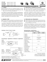
➂
Horizontale Richtcharakteristik (die Teilung der Skala entspricht 6 dB)
Horizontal directivity (the division of the scale corresponds to 6 dB)
Caractéristique horizontale (la division de l’échelle correspond à 6 dB)
Caratteristica direzionale orizzontale (la suddivisione della scala corrisponde a 6 dB)
Directividad horizontal (la división de la escala corresponde a 6 dB)

ELECTRONICS FOR SPECIALISTS ELECTRONICS FOR SPECIALISTS ELECTRONICS FOR SPECIALISTS ELECTRONICS FOR SPECIALISTS ELECTRONICS FOR SPECIALISTS ELECTRONICS
MONACOR INTERNATIONAL GmbH & Co. KG • Zum Falsch 36 • 28307 Bremen • Germany
Copyright
©
by MONACOR INTERNATIONAL. All rights reserved.
A-1423.99.02.02.2020
LR-1000SAT
LR-1000U
LR-1000F
➃
Vertikale Richtcharakteristik (die Teilung der Skala entspricht 6 dB)
Vertical directivity (the division of the scale corresponds to 6 dB)
Caractéristique verticale (la division de l’ échelle correspond à 6 dB)
Caratteristica direzionale verticale (la suddivisione della scala corrisponde a 6 dB)
Directividad vertical (la división de la escala corresponde a 6 dB)
Nederlands
WAARSCHUWING Niet deskundig uitgevoerde
installaties, in het bijzonder
bij boven personen zwevende
systemen, vormen een poten-
tieel gevaar. Daarom mag de installatie uitslui-
tend door gekwalificeerd personeel met kennis
van de geldende normen en veiligheidsvoor-
schriften worden uitgevoerd.
De installatie, in het bijzonder de stabiliteit van
de montageverbindingen, moet met een aan-
gepaste regelmaat worden gecontroleerd.
Dansk
ADVARSEL Installationer der ikke er udført
korrekt udgør en potientiel fare,
specielt hvis systemet er ophængt
hvor der færdes mennesker. Over-
lad derfor altid installtion til personer der er be-
kendt med gældende standard og sikkerheds-
regulativer.
Installationen, specielt stabiliteten af monterin-
gen, skal kontrolleres med jævne mellemrum.
Polski
OSTRZEŻENIE Instalacja, która nie została wyko-
nana prawidłowo, stanowi zagro
żenie, zwłaszcza jeżeli system zo-
stał zawieszony ponad głowami
ludzi.Dlatego też instalacja musi być przepro-
wadzona przez doświadczone osoby, zna jące
standardy i zasady bezpieczeństwa.
Ponadto stabilność zawieszenia i połaczeń musi
być okresowo sprawdzana.
Svenska
VARNING Installationer som inte utförs av ut-
bildad expertis kan om de hänger
över personer utgöra en allvarlig
hälso och skaderisk. Installationer
skall därför ovillkorligen utföras av person som
är kunnig i tekniska säkerhetsfrågor.
Installation av frihängande objekt skall dess-
utom ha regelbunden översyn för att kontrollera
att objekten inte lossnar eller på annat sätt kan
orsaka skada person eller materiel.
Suomi
HUOMIO Asennukset, joita ei ole tehty asian-
mukaisesti, saattavat aiheuttaa vaa-
ratilanteita. Varsinkin jos kaiutinjär-
jestelmä on asennettu riippumaan
ihmisten yllä. Tämän vuoksi asennuksia saa
tehdä vain ammattitaitoinen henkilö, joka on
tutustunut voimassa oleviin standardeihin ja
turvaohjeisiin.
Asennus ja varsinkin liittimien kiinnitykset on
tarkistettava säännöllisin väliajoin.
-
 1
1
-
 2
2
-
 3
3
-
 4
4
-
 5
5
-
 6
6
-
 7
7


IMG STAGELINE LR-1000F Manuale utente
- Categoria
- Altoparlanti
- Tipo
- Manuale utente
- Questo manuale è adatto anche per
in altre lingue
- English: IMG STAGELINE LR-1000F User manual
- français: IMG STAGELINE LR-1000F Manuel utilisateur
- español: IMG STAGELINE LR-1000F Manual de usuario
- Deutsch: IMG STAGELINE LR-1000F Benutzerhandbuch
Altri documenti
-
Monacor AT-52ST Manuale del proprietario
-
 Monacor AT-52H Manuale del proprietario
-
Monacor AT-62H Manuale utente
-
 Monacor AT-62ST Manuale del proprietario
-
Monacor 12.0160 Manuale utente
-
Monacor DN-2618P Manuale utente
-
-
Monacor DNL-1245 Manuale utente
-
Monacor 12.0170 Manuale del proprietario
-

