
For more product details, please visit GIGABYTE's website.
To reduce the impacts on global warming, the packaging materials of this product
are recyclable and reusable. GIGABYTE works with you to protect the environment.
Z490M
User's Manual
Rev. 1001
12ME-Z490M-1001R

Copyright
© 2020 GIGA-BYTE TECHNOLOGY CO., LTD. All rights reserved.
The trademarks mentioned in this manual are legally registered to their respective owners.
Disclaimer
Information in this manual is protected by copyright laws and is the property of GIGABYTE.
Changes to the specications and features in this manual may be made by GIGABYTE
without prior notice.
No part of this manual may be reproduced, copied, translated, transmitted, or published in
any form or by any means without GIGABYTE's prior written permission.
In order to assist in the use of this product, carefully read the User's Manual.
For product-related information, check on our website at: https://www.gigabyte.com
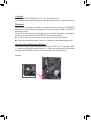
Identifying Your Motherboard Revision
The revision number on your motherboard looks like this: "REV: X.X." For example, "REV:
1.0" means the revision of the motherboard is 1.0. Check your motherboard revision before
updating motherboard BIOS, drivers, or when looking for technical information.
Example:

- 3 -
Table of Contents
Z490M Motherboard Layout ............................................................................................4
Chapter 1 Hardware Installation ....................................................................................5
1-1 Installation Precautions ....................................................................................... 5
1-2 ProductSpecications ........................................................................................ 6
1-3 Installing the CPU ............................................................................................... 9
1-4 Installing the Memory .......................................................................................... 9
1-5 Installing an Expansion Card ............................................................................ 10
1-6 Back Panel Connectors .................................................................................... 10
1-7 Internal Connectors........................................................................................... 12
Chapter 2 BIOS Setup .................................................................................................20
2-1 Startup Screen .................................................................................................. 20
2-2 The Main Menu ................................................................................................. 21
2-3 Favorites (F11) .................................................................................................. 22
2-4 Tweaker ............................................................................................................ 23
2-5 Settings ............................................................................................................. 28
2-6 System Info. ...................................................................................................... 33
2-7 Boot................................................................................................................... 34
2-8 Save & Exit ....................................................................................................... 37
Chapter 3 Appendix .....................................................................................................38
3-1 ConguringaRAIDSet..................................................................................... 38
3-2 Installing an Intel® Optane™ Memory................................................................. 40
3-3 DriversInstallation ............................................................................................ 42
RegulatoryNotices ...................................................................................................... 43
Contact Us .................................................................................................................. 44

- 4 -
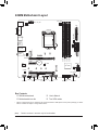
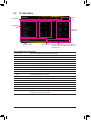
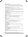
Z490M Motherboard Layout
* The box contents above are for reference only and the actual items shall depend on the product package you obtain.
The box contents are subject to change without notice.
Box Contents
5Z490M motherboard 5User's Manual
5Motherboard driver disc 5Two SATA cables
(Note) TheM.2connectorisreservedonly.Nofunctionalities.
THB_C2
KB_MS_U32
DVI
DP_HDMI
U32_LAN
LGA1200
ATX
AUDIO
DDR4_A1
DDR4_A2
DDR4_B1
DDR4_B2
ATX_12V_2X4
Intel® Z490
CLR_CMOS
M_BIOS
PCIEX1
PCIEX4
PCIEX16
F_U32
CODEC
Z490M
F_USB1LED_C1THB_C1
F_AUDIO
SYS_FAN3
F_USB2COM SPI_TPM F_PANEL
SYS_FAN1
SYS_FAN2
CPU_FAN
iTE®
Super I/O
M2A_SB
426080
M2Q_CPU (Note)
60 80
SATA3
SATA3
1 3
0 2
5
4
BAT
Intel® GbE
LAN
D_LED1
QFLASH_PLUS
QFLED
110
U32C
U32G2

Chapter 1 Hardware Installation
1-1 Installation Precautions
The motherboard contains numerous delicate electronic circuits and components which can
becomedamagedasaresultofelectrostaticdischarge(ESD).Priortoinstallation,carefullyread
the user's manual and follow these procedures:
•Prior to installation, make sure the chassis is suitable for the motherboard.
•Priortoinstallation, donotremoveorbreakmotherboardS/N(SerialNumber)stickeror
warranty sticker provided by your dealer. These stickers are required for warranty validation.
•Always remove the AC power by unplugging the power cord from the power outlet before
installing or removing the motherboard or other hardware components.
•When connecting hardware components to the internal connectors on the motherboard, make
sure they are connected tightly and securely.
•When handling the motherboard, avoid touching any metal leads or connectors.
•It isbest to wear anelectrostatic discharge (ESD)wrist strap when handlingelectronic
componentssuchasamotherboard,CPUormemory.IfyoudonothaveanESDwriststrap,
keepyourhandsdryandrsttouchametalobjecttoeliminatestaticelectricity.
•Prior to installing the motherboard, please have it on top of an antistatic pad or within an
electrostatic shielding container.
•Before connecting or unplugging the power supply cable from the motherboard, make sure
the power supply has been turned off.
•Before turning on the power, make sure the power supply voltage has been set according to
the local voltage standard.
•Before using the product, please verify that all cables and power connectors of your hardware
components are connected.
•To prevent damage to the motherboard, do not allow screws to come in contact with the
motherboard circuit or its components.
•Make sure there are no leftover screws or metal components placed on the motherboard or
within the computer casing.
•Donotplacethecomputersystemonanunevensurface.
•Donotplacethecomputersysteminahigh-temperatureorwetenvironment.
•Turning on the computer power during the installation process can lead to damage to system
components as well as physical harm to the user.
•If you are uncertain about any installation steps or have a problem related to the use of the
product,pleaseconsultacertiedcomputertechnician.
•If you use an adapter, extension power cable, or power strip, ensure to consult with its
installation and/or grounding instructions.
- 5 -

1-2 ProductSpecications
CPU Support for 10th Generation Intel® Core™ i9 processors/Intel® Core™ i7 processors/
Intel® Core™ i5 processors/Intel® Core™ i3 processors/Intel® Pentium® processors/
Intel® Celeron® processors in the LGA1200 package
(Go to GIGABYTE's website for the latest CPU support list.)
L3 cache varies with CPU
Chipset Intel® Z490 Express Chipset
Memory 4xDDR4DIMMsocketssupportingupto128GB(32GBsingleDIMMcapacity)
of system memory
Dualchannelmemoryarchitecture
SupportforDDR43200/2933/2666/2400/2133MHzmemorymodules
* Tosupport3200MHz,youmustuseXMPmemory.
Supportfor ECC Un-bufferedDIMM1Rx8/2Rx8 memory modules (operate in
non-ECC mode)
Supportfornon-ECCUn-bufferedDIMM1Rx8/2Rx8/1Rx16memorymodules
SupportforExtremeMemoryProle(XMP)memorymodules
(Go to GIGABYTE's website for the latest supported memory speeds and memory
modules.)
Onboard
Graphics
Integrated Graphics Processor-Intel®HDGraphicssupport:
- 1xDVI-Dport,supportingamaximumresolutionof1920x1200@60Hz
* TheDVI-DportdoesnotsupportD-Subconnectionbyadapter.
- 1xDisplayPort,supportingamaximumresolutionof4096x2304@60Hz
* SupportforDisplayPort1.4version,HDCP2.3,andHDR.
- 1xHDMIport,supportingamaximumresolutionof4096x2160@30Hz
* SupportforHDMI1.4versionandHDCP2.3.
Support for up to 3 displays at the same time
Maximum shared memory of 512 MB
Audio Realtek® ALC887 codec
HighDenitionAudio
2/4/5.1/7.1-channel
* Tocongure7.1-channelaudio,youneedtoopentheaudiosoftwareandselect
Deviceadvanced settings >PlaybackDevice to changethe default settingrst.
PleasevisitGIGABYTE'swebsitefordetailsonconguringtheaudiosoftware.
LAN Intel®GbELANchip(1000 Mbit/100 Mbit)
Expansion Slots 1 x PCI Express x16 slot, running at x16 (PCIEX16)
* For optimum performance, if only one PCI Express graphics card is to be installed,
be sure to install it in the PCIEX16 slot.
1 x PCI Express x16 slot, running at x4 (PCIEX4)
1 x PCI Express x1 slot
(All of the PCI Express slots conform to PCI Express 3.0 standard.)
Multi-Graphics
Technology SupportforAMDQuad-GPUCrossFire™and2-WayAMDCrossFire™ technologies
Storage Interface 1 x M.2 connector (Socket 3, M key, type 2242/2260/2280/22110 SATA and PCIe
x4/x2SSDsupport)(M2A_SB)
6 x SATA 6Gb/s connectors
SupportforRAID0,RAID1,RAID5,andRAID10
* Referto"1-7InternalConnectors,"fortheinstallationnoticesfortheM.2andSATA
connectors.
Intel® Optane™MemoryReady
- 6 -

USB Chipset:
- 1 x USB Type-C™ port on the back panel, with USB 3.2 Gen 1 support
- 1 x USB 3.2 Gen 2 Type-A port (red) on the back panel
- 6 x USB 3.2 Gen 1 ports (4 ports on the back panel, 2 ports available through
the internal USB header)
- 4 x USB 2.0/1.1 ports available through the internal USB headers
Internal
Connectors
1 x 24-pin ATX main power connector
1x8-pinATX12Vpowerconnector
1 x CPU fan header
3 x system fan headers
1 x addressableLEDstripheader
1xRGBLEDstripheader
6 x SATA 6Gb/s connectors
1 x M.2 Socket 3 connector
1 x front panel header
1 x front panel audio header
1 x USB 3.2 Gen 1 header
2 x USB 2.0/1.1 headers
2 x Thunderbolt™ add-in card connectors
1 x Trusted Platform Module header (For the GC-TPM2.0 SPI/GC-TPM2.0 SPI
2.0 module only)
1 x serial port header
1 x Clear CMOS jumper
1 x Q-Flash Plus button
Back Panel
Connectors
1 x PS/2 keyboard/mouse port
1xDVI-Dport
1xDisplayPort
1xHDMIport
1 x USB Type-C™ port, with USB 3.2 Gen 1 support
1 x USB 3.2 Gen 2 Type-A port (red)
4 x USB 3.2 Gen 1 ports
1xRJ-45port
3 x audio jacks
I/O Controller iTE® I/O Controller Chip
Hardware
Monitor
Voltagedetection
Temperature detection
Fan speed detection
Overheating warning
Fan fail warning
Fan speed control
* Whether the fan speed control function is supported will depend on the fan you install.
- 7 -

BIOS 1x256Mbitash
Use of licensed AMI UEFI BIOS
PnP1.0a,DMI2.7,WfM2.0,SMBIOS2.7,ACPI5.0
Unique Features Support for APP Center
* Available applications in APP Center may vary by motherboard model. Supported
functionsofeachapplicationmayalsovarydependingonmotherboardspecications.
- @BIOS
- EasyTune
- Fast Boot
- Game Boost
- ON/OFFCharge
- RGBFusion
- Smart Backup
- SystemInformationViewer
Support for Q-Flash Plus
Support for Q-Flash
Support for Xpress Install
Bundled
Software
Norton® Internet Security (OEM version)
cFosSpeed
Operating
System Support for Windows 10 64-bit
Form Factor Micro ATX Form Factor; 24.4cm x 24.4cm
* GIGABYTEreservestherighttomakeanychangestotheproductspecicationsandproduct-relatedinformationwithout
prior notice.
Please visit GIGABYTE's website
for support lists of CPU, memory
modules,SSDs,andM.2devices.
Please visit the Support\Utility List
page on GIGABYTE's website to
download the latest version of apps.
- 8 -

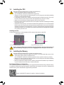
1-3 Installing the CPU
ReadthefollowingguidelinesbeforeyoubegintoinstalltheCPU:
•Make sure that the motherboard supports the CPU.
(Go to GIGABYTE's website for the latest CPU support list.)
•Always turn off the computer and unplug the power cord from the power outlet before installing
the CPU to prevent hardware damage.
•Locate the pin one of the CPU. The CPU cannot be inserted if oriented incorrectly. (Or you may
locate the notches on both sides of the CPU and alignment keys on the CPU socket.)
•Apply an even and thin layer of thermal grease on the surface of the CPU.
•DonotturnonthecomputeriftheCPUcoolerisnotinstalled,other wiseoverheatinganddamage
of the CPU may occur.
•SettheCPUhostfrequencyinaccordancewiththeCPUspecications.Itisnotrecommended
thatthesystembusfrequencybesetbeyondhardwarespecicationssinceitdoesnotmeetthe
standard requirements for the peripherals. If you wish to set the frequency beyond the standard
specications,pleasedosoaccordingtoyourhardwarespecicationsincludingtheCPU,graphics
card, memory, hard drive, etc.
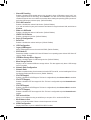
Installing the CPU
Locate the alignment keys on the motherboard CPU socket and the notches on the CPU.
1-4 Installing the Memory
Readthefollowingguidelinesbeforeyoubegintoinstallthememory:
•Make sure that the motherboard supports the memory. It is recommended that memory of the
same capacity, brand, speed, and chips be used.
(Go to GIGABYTE's website for the latest supported memory speeds and memory modules.)
•Always turn off the computer and unplug the power cord from the power outlet before installing
the memory to prevent hardware damage.
•Memory modules have a foolproof design. A memory module can be installed in only one direction.
If you are unable to insert the memory, switch the direction.
DualChannelMemoryConguration
ThismotherboardprovidesfourmemorysocketsandsupportsDualChannelTechnology.Afterthememory
isinstalled,theBIOSwillautomaticallydetectthespecicationsandcapacityofthememory.EnablingDual
Channel memory mode will double the original memory bandwidth.
Please visit GIGABYTE's website for details on hardware installation.
Do not remove the CPU socket cover before inserting the CPU. It may pop off from the load
plate automatically during the process of re-engaging the lever after you insert the CPU.
Triangle Pin One Marking on the CPU
NotchNotch
LGA1200 CPU
Alignment
Key
Alignment
Key
LGA1200 CPU Socket
Pin One Corner of the CPU Socket
- 9 -

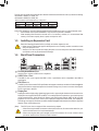
1-5 Installing an Expansion Card
Readthefollowingguidelinesbeforeyoubegintoinstallanexpansioncard:
•Make sure the motherboard supports the expansion card. Carefully read the manual that came
with your expansion card.
•Always turn off the computer and unplug the power cord from the power outlet before installing
an expansion card to prevent hardware damage.
DuetoCPUlimitations,readthefollowingguidelinesbeforeinstallingthememoryinDualChannelmode.
1. DualChannelmodecannotbeenabledifonlyonememorymoduleisinstalled.
2. WhenenablingDual Channelmodewithtwoor fourmemory modules, it is recommendedthat
memory of the same capacity, brand, speed, and chips be used.
The four memory sockets are divided into two channels and each channel has two memory sockets as following:
ChannelA:DDR4_A1,DDR4_A2
ChannelB:DDR4_B1,DDR4_B2
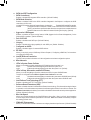
1-6 Back Panel Connectors
PS/2 Keyboard/Mouse Port
Use this port to connect a PS/2 mouse or keyboard.
USB 3.2 Gen 1 Port
TheUSB3.2Gen1portsupportstheUSB3.2Gen1specicationandiscompatibletotheUSB2.0
specication.
DVI-D Port (Note)
TheDVI-Dpor tconformstotheDVI-Dspecicationandsupportsamaximumresolutionof1920x1200@60Hz
(the actual resolutions supported depend on the monitor being used). Connect a monitor that supports
DVI-Dconnectiontothisport.
DisplayPort
DisplayPortdelivershighqualitydigitalimagingandaudio,supportingbi-directionalaudiotransmission.
DisplayPortcansupportbothDPCPandHDCP2.3contentprotectionmechanisms.Itprovidesimproved
visualssupportingRec.2020(WideColorGamut)andHighDynamicRange(HDR)forBlu-rayUHD
playback.YoucanusethisporttoconnectyourDisplayPort-supportedmonitor.Note:TheDisplayPort
Technologycansuppor tamaximumresolutionof409 6x2304@60Hzbuttheactualresolutionssuppor ted
depend on the monitor being used.
RecommandedDualChannelMemoryConguration:
DDR4_A1 DDR4_A2 DDR4_B1 DDR4_B2
2 Modules - - DS/SS - - DS/SS
4 Modules DS/SS DS/SS DS/SS DS/SS
(SS=Single-Sided,DS=Double-Sided,"--"=NoMemory)
(Note) TheDVI-DportdoesnotsupportD-Subconnectionbyadapter.
•Whenremovingthecableconnectedtoabackpanelconnector,rstremovethecablefromyour
device and then remove it from the motherboard.
•Whenremovingthecable,pullitstraightoutfromtheconnector.Donotrockitsidetosideto
prevent an electrical short inside the cable connector.
- 10 -

USB 3.2 Gen 1 Port (Q-Flash Plus Port)
TheUSB3.2Gen1portsupportstheUSB3.2Gen1specicationandiscompatibletotheUSB2.0
specication.UsethisportforUSBdevices.BeforeusingQ-FlashPlus(Note), make sure to insert the
USBashdriveintothisportrst.
Line In/Rear Speaker Out (Blue)
The line in jack. Use this audio jack for line in devices such as an optical drive, walkman, etc.
Line Out/Front Speaker Out (Green)
The line out jack.
Mic In/Center/Subwoofer Speaker Out (Pink)
The Mic in jack.
(Note) ToenabletheQ-FlashPlusfunctionpleasevisitthe"UniqueFeatures"webpageofGIGABYTE'swebsite.
•Tosetupatriple-displayconguration,youmustinstallmotherboarddriversintheoperatingsystemrst.
•AfterinstallingtheDisplayPort/HDMIdevice,makesuretosetthedefaultsoundplaybackdevicetoDisplayPort/
HDMI.(Theitemnamemaydifferdependingonyouroperatingsystem.)
HDMI Port
TheHDMIportsupportsHDCP2.3andDolbyTrueHDandDTSHDMaster
Audioformats.Italsosupportsupto192KHz/16bit7.1-channelLPCMaudio
output.YoucanusethisporttoconnectyourHDMI-supportedmonitor.The
maximumsupported resolution is 4096x2160@30 Hz, but the actual resolutions supported are
dependent on the monitor being used.
USB 3.2 Gen 2 Type-A Port (Red)
TheUSB3.2Gen2Type-AportsupportstheUSB3.2Gen2specicationandiscompatibletotheUSB
3.2Gen1andUSB2.0specication.UsethisportforUSBdevices.
USB Type-C™ Port
ThereversibleUSBportsupportstheUSB3.2Gen1specicationandiscompatibletotheUSB2.0
specication.UsethisportforUSBdevices.
RJ-45 LAN Port
TheGigabitEthernetLANportprovidesInternetconnectionatupto1Gbpsdatarate.Thefollowing
describesthestatesoftheLANportLEDs.
ActivityLED
Connection/
SpeedLED
LANPort
ActivityLED:
Connection/SpeedLED:
State Description
Orange 1 Gbps data rate
Green 100 Mbps data rate
Off 10 Mbps data rate
State Description
Blinking Datatransmissionorreceivingisoccurring
On Nodatatransmissionorreceivingisoccurring
AudioJackCongurations:
Jack Headphone/
2-channel 4-channel 5.1-channel 7.1-channel
LineIn/RearSpeakerOut a a a
Line Out/Front Speaker Out a a a a
Mic In/Center/Subwoofer Speaker Out a a
Front Panel Line Out/Side Speaker Out a
PleasevisitGIGABYTE'swebsitefordetailsonconguringtheaudiosoftware.
- 11 -

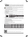
1-7 Internal Connectors
Readthefollowingguidelinesbeforeconnectingexternaldevices:
•First make sure your devices are compliant with the connectors you wish to connect.
•Before installing the devices, be sure to turn off the devices and your computer. Unplug the power
cord from the power outlet to prevent damage to the devices.
•After installing the device and before turning on the computer, make sure the device cable has
been securely attached to the connector on the motherboard.
4 98
11
7
17
2
7
510 14
1
4
15 12 13
34
1) ATX_12V_2X4
2) ATX
3) CPU_FAN
4) SYS_FAN1/2/3
5) LED_C1
6) D_LED1
7) SATA3 0/1/2/3/4/5
8) M2A_SB
9) F_PANEL
10) F_ AUDIO
11) F_U32
12) F_USB1/F_USB2
13) SPI_TPM
14) THB_C1/THB_C2
15) COM
16) BAT
17) CLR_CMOS
18) QFLASH_PLUS
6
16
18
14
- 12 -

DEBUG
PORT
G.QBOFM
131
2412
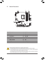
ATX
1/2) ATX_12V_2X4/ATX (2x4 12V Power Connector and 2x12 Main Power Connector)
With the use of the power connector, the power supply can supply enough stable power to all the
componentsonthemotherboard.Beforeconnectingthepowerconnector,rstmakesurethepower
supply is turned off and all devices are properly installed. The power connector possesses a foolproof
design. Connect the power supply cable to the power connector in the correct orientation.
The12VpowerconnectormainlysuppliespowertotheCPU.Ifthe12Vpowerconnectorisnotconnected,
the computer will not start.
To meet expansion requirements, it is recommended that a power supply that can withstand high
power consumption be used (500W or greater). If a power supply is used that does not provide
the required power, the result can lead to an unstable or unbootable system.
ATX:
PinNo. Denition PinNo. Denition
13.3V 13 3.3V
23.3V 14 -12V
3GND 15 GND
4+5V 16 PS_ON(softOn/Off)
5GND 17 GND
6+5V 18 GND
7GND 19 GND
8 Power Good 20 NC
95VSB(standby+5V) 21 +5V
10 +12V 22 +5V
11 +12V(Onlyfor2x12-pin
ATX)
23 +5V(Onlyfor2x12-pinATX)
12 3.3V(Onlyfor2x12-pin
ATX)
24 GND(Onlyfor2x12-pin
ATX)
ATX_12V_2X4:
PinNo. Denition PinNo. Denition
1GND(Onlyfor2x4-pin
12V)
5+12V(Onlyfor2x4-pin12V)
2GND(Onlyfor2x4-pin
12V)
6+12V(Onlyfor2x4-pin12V)
3GND 7+12V
4GND 8+12V
ATX_12V_2X4
DEBUG
PORT
G.QBOFM
41
85
3/4) CPU_FAN/SYS_FAN1/2/3 (Fan Headers)
All fan headers on this motherboard are 4-pin. Most fan headers possess a foolproof insertion design.
When connecting a fan cable, be sure to connect it in the correct orientation (the black connector wire
is the ground wire). The speed control function requires the use of a fan with fan speed control design.
For optimum heat dissipation, it is recommended that a system fan be installed inside the chassis.
PinNo. Denition
1GND
2VoltageSpeedControl
3 Sense
4 PWM Speed Control
CPU_FAN/SYS_FAN1
DEBUG
PORT
G.QBOFM
DEBUG
PORT
G.QBOFM
1 1
SYS_FAN2 SYS_FAN3
DEBUG
PORT
G.QBOFM
1
- 13 -

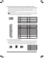
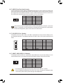
5) LED_C1 (RGB LED Strip Header)
Theheadercanbeusedtoconnectastandard5050RGBLEDstrip(12V/G/R/B),withmaximumpower
ratingof2A(12V)andmaximumlengthof2m.
PinNo. Denition
112V
2 G
3R
4 B
ConnectyourRGBLEDstriptotheheader.Thepowerpin(marked
withatriangleontheplug)oftheLEDstripmustbeconnectedto
Pin1(12V)ofthisheader.Incorrectconnectionmayleadtothe
damageoftheLEDstrip.
1
DEBUG
PORT
G.QBOFM
RGBLEDStrip
1
12V
6) D_LED1 (Addressable LED Strip Header)
Theheadercanbeusedtoconnectastandard5050addressableLEDstrip,withmaximumpowerrating
of5A(5V)andmaximumnumberof1000LEDs.
PinNo. Denition
1V(5V)
2D
3NoPin
4 G
Before installing the devices, be sure to turn off the devices and your computer. Unplug the power
cord from the power outlet to prevent damage to the devices.
Forhowtoturnon/offthelightsoftheLEDstrippleasevisitthe"UniqueFeatures"webpageof
GIGABYTE's website.
F_USB30 F_U
B_
F_ F_
_
B
BS_
B
SB_
B
_S
S_
_
B
_U
_
B
S
123
123
123
123
1
1
1
1
BSS
S
_S
SSU
1 2 3 4 5
S3 BSSS
U
__ 3
F_USB3F
S _
S _
S _
SF
B_
B_
F
_0
S
S
_0F
_F
_
_
__B
U
S _S
_ SF_
B
USB0_B
B_
B_
F_USB3
F_USB303
_
_3U
S_
1
Connect your addressable LEDstrip tothe header.The power
pin(markedwithatriangleontheplug)oftheLEDstripmustbe
connectedtoPin1oftheaddressableLEDstripheader.Incorrect
connectionmayleadtothedamageoftheLEDstrip.
AddressableLED
Strip
1
- 14 -

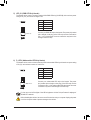
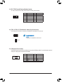
7) SATA3 0/1/2/3/4/5 (SATA 6Gb/s Connectors)
The SATA connectors conform to SATA 6Gb/s standard and are compatible with SATA 3Gb/s and SATA
1.5Gb/s standard. Each SATA connector supports a single SATA device. The Intel® Chipset supports
RAID0,RAID1,RAID5,andRAID10.RefertoChapter3,"ConguringaRAIDSet,"forinstructions
onconguringaRAIDarray.
PinNo. Denition
1GND
2 TXP
3TXN
4GND
5RXN
6RXP
7GND
Toenablehot-pluggingfortheSATAports,refertoChapter2,"BIOSSetup,""Settings\IOPorts\
SATAAndRSTConguration,"formoreinformation.
DEBUG
PORT
G.QBOFM
SATA3
SATA3
3 2
1 0
5
4
DEBUG
PORT
G.QBOFM
DEBUG
PORT
G.QBOFM
DEBUG
PORT
G.QBOFM
DEBUG
PORT
G.QBOFM
7
1
7
1
17
17
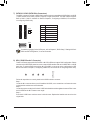
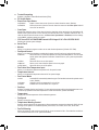
8) M2A_SB (M.2 Socket 3 Connector)
TheM.2connectorsuppor tsM.2SATASSDsorM.2PCIeSSDsandsupportR AIDconguration.Please
notethatanM.2PCIeSSDcannotbeusedtocreateaRAIDseteitherwithanM.2SATASSDoraSATA
harddrive.TocreateaRAIDarraywithanM.2PCIeSSD,youmustsetupthecongurationinUEFI
BIOSmode.RefertoChapter3,"ConguringaRAIDSet,"forinstructionsonconguringaRAIDarray.
FollowthestepsbelowtocorrectlyinstallanM.2SSDintheM.2connector.
Step 1:
LocatetheM.2connectorwhereyouwillinstalltheM.2SSD,useascrewdrivertounfastenthescrew
on the heatsink and then remove the heatsink.
Step 2:
LocatethepropermountingholefortheM.2SSDtobeinstalledandthentightenthestandoffrst.Insert
theM.2SSDintotheM.2connectoratanangle.
Step 3:
PresstheM.2SSDdownandthensecureitwiththescrew.Replacetheheatsinkandsecureittothe
original hole.
F_USB30 F_U
B_
F_ F_
_
B
BS_
B
SB_
B
_S
S_
_
B
_U
_
B
S
123
123
123
123
1
1
1
1
BSS
S
_S
SSU
1 2 3 4 5
S3 BSSS
U
__ 3
F_USB3F
S _
S _
S _
SF
B_
B_
F
_0
S
S
_0F
_F
_
_
__B
U
S _S
_ SF_
B
USB0_B
B_
B_
F_USB3
F_USB303
_
_3U
S_
80110 60 42
- 15 -

Installation Notices for the M.2 and SATA Connectors:
The availability of the SATA connectors may be affected by the type of device installed in the M.2 connector.
Refertothefollowingtablesfordetails.
SATA3 0 SATA3 1 SATA3 2 SATA3 3 SATA3 4 SATA3 5
M.2SATASSD ara a a a
M.2PCIeSSD
a a a a a a
NoM.2SSDInstalled a a a a a a
a: Available, r:Notavailable
Connector
Type of
M.2SSD
The front panel design may differ by chassis. A front panel module mainly consists of power
switch,resetswitch,powerLED,harddriveactivityLED,speakerandetc.Whenconnecting
your chassis front panel module to this header, make sure the wire assignments and the pin
assignments are matched correctly.
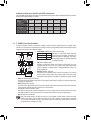
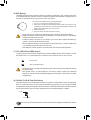
9) F_PANEL (Front Panel Header)
Connect the power switch, reset switch, speaker, chassis intrusion switch/sensor and system status
indicatoronthechassistothisheaderaccordingtothepinassignmentsbelow.Notethepositiveand
negative pins before connecting the cables.
System Status LED
S0 On
S3/S4/S5 Off
•PW (PowerSwitch,Red):
Connects to the power switch on the chassis front panel. You may
congure thewaytoturnoffyoursystemusingthepowerswitch
(refer to Chapter 2,"BIOS Setup," "Settings\PlatformPower," for
more information).
•SPEAK (Speaker, Orange):
Connects to the speaker on the chassis front panel. The system
reports system startup status by issuing a beep code. One single
short beep will be heard if no problem is detected at system startup.
•PLED/PWR_LED (PowerLED,Yellow/Purple):
Connects to the power status indicator
onthechassisfrontpanel.TheLEDison
whenthesystemisoperating.TheLEDis
off when the system is in S3/S4 sleep state
or powered off (S5).
•HD (HardDriveActivityLED,Blue):
ConnectstotheharddriveactivityLEDonthechassisfrontpanel.TheLEDisonwhentheharddrive
is reading or writing data.
•RES (ResetSwitch,Green):
Connects to the reset switch on the chassis front panel. Press the reset switch to restart the computer
ifthecomputerfreezesandfailstoperformanormalrestart.
•CI (Chassis Intrusion Header, Gray):
Connects to the chassis intrusion switch/sensor on the chassis that can detect if the chassis cover
has been removed. This function requires a chassis with a chassis intrusion switch/sensor.
•NC (Orange):Noconnection.
PowerLED
DEBUG
PORT
G.QBOFM
1
2
19
20
CI-
CI+
PWR_LED-
PWR_LED+
PLED-
PW-
SPEAK+
SPEAK-
PLED+
PW+
PowerLED
HD-
RES+
HD+
RES-
HardDrive
ActivityLED
Reset
Switch Chassis
Intrusion Header
Power Switch Speaker
PWR_LED-
NC
NC
- 16 -

10) F_AUDIO (Front Panel Audio Header)
ThefrontpanelaudioheadersupportsHighDenitionaudio(HD).Youmayconnectyourchassisfront
panel audio module to this header. Make sure the wire assignments of the module connector match the
pin assignments of the motherboard header. Incorrect connection between the module connector and
the motherboard header will make the device unable to work or even damage it.
Some chassis provide a front panel audio module that has separated connectors on each wire
instead of a single plug. For information about connecting the front panel audio module that has
different wire assignments, please contact the chassis manufacturer.
PinNo. Denition PinNo. Denition
1 MIC2_L 6 Sense
2GND 7FAUDIO_JD
3MIC2_R 8NoPin
4NC 9LINE2_L
5LINE2_R 10 Sense
F_USB30 F_U
B_
F_ F_
_
B
BS_
B
SB_
B
_S
S_
_
B
_U
_
B
S
123
123
123
123
1
1
1
1
BSS
S
_S
SSU
1 2 3 4 5
S3 BSSS
U
__ 3
F_USB3F
S _
S _
S _
SF
B_
B_
F
_0
S
S
_0F
_F
_
_
__B
U
S _S
_ SF_
B
USB0_B
B_
B_
F_USB3
F_USB303
_
_3U
S_
9 1
10 2
11) F_U32 (USB 3.2 Gen 1 Header)
TheheaderconformstoUSB3.2Gen1andUSB2.0specicationandcanprovidetwoUSBports.For
purchasingtheoptional3.5"frontpanelthatprovidestwoUSB3.2Gen1ports,pleasecontactthelocal
dealer.
F_USB30 F_U
B_
F_ F_
_
B
BS_
B
SB_
B
_S
S_
_
B
_U
_
B
S
123
123
123
123
1
1
1
1
BSS
S
_S
SSU
1 2 3 4 5
S3 BSSS
U
__ 3
F_USB3F
S _
S _
S _
SF
B_
B_
F
_0
S
S
_0F
_F
_
_
__B
U
S _S
_ SF_
B
USB0_B
B_
B_
F_USB3
F_USB303
_
_3U
S_
10
20 1
11
PinNo. Denition PinNo. Denition PinNo. Denition
1VBUS 8D1- 15 SSTX2-
2SSRX1- 9D1+ 16 GND
3SSRX1+ 10 NC 17 SSRX2+
4GND 11 D2+ 18 SSRX2-
5 SSTX1- 12 D2- 19 VBUS
6 SSTX1+ 13 GND 20 NoPin
7GND 14 SSTX2+
12) F_USB1/F_USB2 (USB 2.0/1.1 Headers)
TheheadersconformtoUSB2.0/1.1specication.EachUSBheadercanprovidetwoUSBportsviaan
optional USB bracket. For purchasing the optional USB bracket, please contact the local dealer.
PinNo. Denition PinNo. Denition
1Power(5V) 6USBDY+
2Power(5V) 7GND
3USBDX- 8GND
4USBDY- 9NoPin
5USBDX+ 10 NC
•DonotplugtheIEEE1394bracket(2x5-pin)cableintotheUSB2.0/1.1header.
•Prior to installing the USB bracket, be sure to turn off your computer and unplug the power
cord from the power outlet to prevent damage to the USB bracket.
DEBUG
PORT
G.QBOFM
10
9
2
1
- 17 -

14) THB_C1/THB_C2 (Thunderbolt™ Add-in Card Connectors)
The connectors are used to connect to a GIGABYTE Thunderbolt™ add-in card.
Supports a Thunderbolt™ add-in card.
12
11
2
1
13) SPI_TPM (Trusted Platform Module Header)
You may connect an SPI TPM (Trusted Platform Module) to this header.
PinNo. Denition PinNo. Denition
1DataOutput 7Chip Select
2Power(3.3V) 8GND
3NoPin 9IRQ
4NC 10 NC
5DataInput 11 NC
6CLK 12 RST
F_USB30 F_U
B_
F_ F_
_
B
BS_
B
SB_
B
_S
S_
_
B
_U
_
B
S
123
123
123
123
1
1
1
1
BSS
S
_S
SSU
1 2 3 4 5
S3 BSSS
U
__ 3
F_USB3F
S _
S _
S _
SF
B_
B_
F
_0
S
S
_0F
_F
_
_
__B
U
S _S
_ SF_
B
USB0_B
B_
B_
F_USB3
F_USB303
_
_3U
S_
F_USB30 F_U
B_
F_ F_
_
B
BS_
B
SB_
B
_S
S_
_
B
_U
_
B
S
123
123
123
123
1
1
1
1
BSS
S
_S
SSU
1 2 3 4 5
S3 BSSS
U
__ 3
F_USB3F
S _
S _
S _
SF
B_
B_
F
_0
S
S
_0F
_F
_
_
__B
U
S _S
_ SF_
B
USB0_B
B_
B_
F_USB3
F_USB303
_
_3U
S_
1
F_USB30 F_U
B_
F_ F_
_
B
BS_
B
SB_
B
_S
S_
_
B
_U
_
B
S
123
123
123
123
1
1
1
1
BSS
S
_S
SSU
1 2 3 4 5
S3 BSSS
U
__ 3
F_USB3F
S _
S _
S _
SF
B_
B_
F
_0
S
S
_0F
_F
_
_
__B
U
S _S
_ SF_
B
USB0_B
B_
B_
F_USB3
F_USB303
_
_3U
S_
1THB_C2
THB_C1
15) COM (Serial Port Header)
The COM header can provide one serial port via an optional COM port cable. For purchasing the optional
COM port cable, please contact the local dealer.
PinNo. Denition PinNo. Denition
1NDCD- 6NDSR-
2NSIN 7NRTS-
3NSOUT 8NCTS-
4NDTR- 9NRI-
5GND 10 NoPin
10
9
2
1
- 18 -

17) CLR_CMOS (Clear CMOS Jumper)
UsethisjumpertocleartheBIOScongurationandresettheCMOSvaluestofactorydefaults.Toclear
the CMOS values, use a metal object like a screwdriver to touch the two pins for a few seconds.
•Always turn off your computer and unplug the power cord from the power outlet before clearing
the CMOS values.
•After system restart,go to BIOS Setup toloadfactory defaults (selectLoad Optimized
Defaults)ormanuallyconguretheBIOSsettings(refertoChapter2,"BIOSSetup,"forBIOS
congurations).
Open:Normal
Short:ClearCMOSValues
18) QFLASH_PLUS (Q-Flash Plus Button)
Q-Flash Plus allows you to update the BIOS when your system is off (S5 shutdown state). Save the latest
BIOSonaUSBthumbdriveandplugitintothededicatedport,andthenyoucannowashtheBIOS
automaticallybysimplypressingtheQ-FlashPlusbutton.TheQFLEDwillashwhentheBIOSmatching
andashingactivitiesstartandwillstopashingwhenthemainBIOSashingiscomplete.
ForhowtouseQ-FlashPluspleasevisitthe"UniqueFeatures"webpageofGIGABYTE'swebsite.
16) BAT (Battery)
Thebatteryprovidespowertokeepthevalues(suchasBIOScongurations,date,andtimeinformation)
intheCMOSwhenthecomputeristurnedoff.Replacethebatterywhenthebatteryvoltagedropstoa
low level, or the CMOS values may not be accurate or may be lost.
You may clear the CMOS values by removing the battery:
1. Turn off your computer and unplug the power cord.
2. Gently remove the battery from the battery holder and wait for one minute. (Or use
a metal object like a screwdriver to touch the positive and negative terminals of the
battery holder, making them short for 5 seconds.)
3. Replacethebattery.
4. Plug in the power cord and restart your computer.
•Always turn off your computer and unplug the power cord before replacing the battery.
•Replacethebatterywithanequivalentone.Damagetoyourdevicesmayoccurifthebattery
is replaced with an incorrect model.
•Contact the place of purchase or local dealer if you are not able to replace the battery by
yourself or uncertain about the battery model.
•When installing the battery, note the orientation of the positive side (+) and the negative side
(-) of the battery (the positive side should face up).
•Used batteries must be handled in accordance with local environmental regulations.
QFLED
QFLASH_PLUS
- 19 -

•When the system is not stable as usual, select the Load Optimized Defaults item to set your system to its
defaults.
•The BIOS Setup menus described in this chapter are for reference only and may differ by BIOS version.
BIOS (Basic Input and Output System) records hardware parameters of the system in the CMOS on the
motherboard. Its major functions include conducting the Power-On Self-Test (POST) during system startup,
saving system parameters and loading operating system, etc. BIOS includes a BIOS Setup program that allows
theusertomodifybasicsystemcongurationsettingsortoactivatecertainsystemfeatures.
When the power is turned off, the battery on the motherboard supplies the necessary power to the CMOS to
keepthecongurationvaluesintheCMOS.
ToaccesstheBIOSSetupprogram,pressthe<Delete>keyduringthePOSTwhenthepoweristurnedon.
ToupgradetheBIOS,useeithertheGIGABYTEQ-Flashor@BIOSutility.
•Q-Flash allows the user to quickly and easily upgrade or back up BIOS without entering the operating
system.
•@BIOSisaWindows-basedutilitythatsearchesanddownloadsthelatestversionofBIOSfromthe
Internet and updates the BIOS.
Chapter 2 BIOS Setup
•BecauseBIOSashingispotentiallyrisky,ifyoudonotencounterproblemsusingthecurrentversion of
BIOS,itisrecommendedthatyounotashtheBIOS.ToashtheBIOS,doitwithcaution.InadequateBIOS
ashingmayresultinsystemmalfunction.
•It is recommended that you not alter the default settings (unless you need to) to prevent system instability
or other unexpected results. Inadequately altering the settings may result in system's failure to boot. If this
occurs,trytocleartheCMOSvaluesandresettheboardtodefaultvalues.(Refertothe"LoadOptimized
Defaults"sectioninthischapterorintroductionsofthebattery/clearCMOSjumperinChapter1forhowto
clear the CMOS values.)
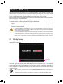
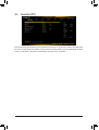
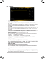
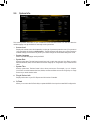
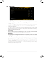
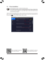
2-1 Startup Screen
The following startup Logo screen will appear when the computer boots.
(SampleBIOSVersion:T0d)
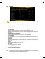
Therearet wodifferentBIOSmodesasfollowsandyoucanusethe<F2>keytoswitchbetweenthetwomodes.
The Classic Setup mode provides detailed BIOS settings. You can press the arrow keys on your keyboard
tomoveamongtheitemsandpress<Enter>toacceptorenterasub-menu.Oryoucanuseyourmouse
to select the item you want. Easy Mode allows users to quickly view their current system information or
to make adjustments for optimum performance. In Easy Mode, you can use your mouse to move through
congurationitems.
Function Keys
- 20 -
La pagina si sta caricando...
La pagina si sta caricando...
La pagina si sta caricando...
La pagina si sta caricando...
La pagina si sta caricando...
La pagina si sta caricando...
La pagina si sta caricando...
La pagina si sta caricando...
La pagina si sta caricando...
La pagina si sta caricando...
La pagina si sta caricando...
La pagina si sta caricando...
La pagina si sta caricando...
La pagina si sta caricando...
La pagina si sta caricando...
La pagina si sta caricando...
La pagina si sta caricando...
La pagina si sta caricando...
La pagina si sta caricando...
La pagina si sta caricando...
La pagina si sta caricando...
La pagina si sta caricando...
La pagina si sta caricando...
La pagina si sta caricando...
-
 1
1
-
 2
2
-
 3
3
-
 4
4
-
 5
5
-
 6
6
-
 7
7
-
 8
8
-
 9
9
-
 10
10
-
 11
11
-
 12
12
-
 13
13
-
 14
14
-
 15
15
-
 16
16
-
 17
17
-
 18
18
-
 19
19
-
 20
20
-
 21
21
-
 22
22
-
 23
23
-
 24
24
-
 25
25
-
 26
26
-
 27
27
-
 28
28
-
 29
29
-
 30
30
-
 31
31
-
 32
32
-
 33
33
-
 34
34
-
 35
35
-
 36
36
-
 37
37
-
 38
38
-
 39
39
-
 40
40
-
 41
41
-
 42
42
-
 43
43
-
 44
44


in altre lingue
- English: Gigabyte Z490M Owner's manual
Documenti correlati
-
Gigabyte B560M D3H Manuale del proprietario
-
Gigabyte B560 HD3 Manuale del proprietario
-
-
-
-
-
-
-
Gigabyte W480M VISION W Manuale del proprietario