
ML20
--------------------------------------------------------------------------------- 8014351.YGT4 0315 COMAT -----------------------------------------------------------------------------
More representatives and agencies at www.sick.com ∙ Subject to change
without notice ∙ The specied product features and technical data do not
represent any guarantee.
Weitere Niederlassungen nden Sie unter www.sick.com ∙ Irrtümer
und Änderungen vorbehalten ∙ Angegebene Produkteigenschaften und
technische Daten stellen keine Garantieerklärung dar.
Plus de représentations et d’agences à l’adresse www.sick.com ∙ Sujet à
modication sans préavis ∙ Les caractéristiques de produit et techniques
indiquées ne constituent pas de déclaration de garantie.
Para mais representantes e agências, consulte www.sick.com ∙ Alterações
poderão ser feitas sem prévio aviso ∙ As características do produto e os
dados técnicos apresentados não constituem declaração de garantia.
Altri rappresentanti ed agenzie si trovano su www.sick.com ∙ Contenuti
soggetti a modiche senza preavviso ∙ Le caratteristiche del prodotto e i dati
tecnici non rappresentano una dichiarazione di garanzia.
Más representantes y agencias en www.sick.com ∙ Sujeto a cambio sin
previo aviso ∙ Las características y los datos técnicos especicados no
constituyen ninguna declaración de garantía.
欲了解更多代表机构和代理商信息,请登录 www.sick.com ∙
如有更改,不另行通知 ∙ 对所给出的产品特性和技术参数
的正确性不予保证。
その他の営業所は www.sick.com よりご覧ください・予告なしに変更されるこ
とがあります・記載されている製品機能および技術データは保証を明示する
ものではありません。
Australia
Phone +61 3 9457 0600
Belgium/Luxembourg
Phone +32 (0)2 466 55 66
Brasil
Phone +55 11 3215-4900
Canada
Phone +1 905 771 14 44
Česká republika
Phone +420 2 57 91 18 50
China
Phone +86 4000 121 000
+852-2153 6300
Danmark
Phone +45 45 82 64 00
Deutschland
Phone +49 211 5301-301
España
Phone +34 93 480 31 00
France
Phone +33 1 64 62 35 00
Great Britain
Phone +44 (0)1727 831121
India
Phone +91–22–4033 8333
Israel
Phone +972-4-6801000
Italia
Phone +39 02 27 43 41
Japan
Phone +81 (0)3 5309 2112
Magyarország
Phone +36 1 371 2680
Nederland
Phone +31 (0)30 229 25 44
Österreich
Phone +43 (0)22 36 62 28 8-0
Norge
Phone +47 67 81 50 00
Polska
Phone +48 22 837 40 50
România
Phone +40 356 171 120
Russia
Phone +7-495-775-05-30
Schweiz
Phone +41 41 619 29 39
Singapore
Phone +65 6744 3732
Slovenija
Phone +386 (0)1-47 69 990
South Africa
Phone +27 11 472 3733
South Korea
Phone +82 2 786 6321/4
Suomi
Phone +358-9-25 15 800
Sverige
Phone +46 10 110 10 00
Taiwan
Phone +886-2-2375-6288
Türkiye
Phone +90 (216) 528 50 00
United Arab Emirates
Phone +971 (0) 4 8865 878
USA/México
Phone +1(952) 941-6780
BZ int43
Please find detailed addresses and additional representatives and agencies in
all major industrial nations at www.sick.com
SICK AG, Erwin-Sick-Strasse 1, D-79183 Waldkirch
---------------------------------------------------------------------------------------------------------------------------------------------------------------------------------------------------------------------------------------------------
ENGLISH
Markless Sensor
Quickstart ML20
Available for download at www.mysick.com/en/ML20:
– Control codes
– Detailed operating instructions
– SOPAS engineering tool
Safety note
• Read operating instructions before commissioning
• Connection, mounting and setting must be performed by qualied
personnel
• Protect devices from moisture and contamination during commis-
sioning
• No safety component pursuant to EU machinery directive
• The markless sensor is equipped with LED lighting. The ML20 is a
device of risk group 1 (low risk) pursuant to IEC 62471:2006
System requirement
A prerequisite for the function of ML20 are encoder impulses that can
also be generated by a motor feedback system. The type and resolution
of the signals must be parameterized at the device before initial com-
missioning (see step
3 ).
Intended use
The sensor ML20 is an optoelectronic sensor that is used for contact-
free recognition of repeating patterns.
Commissioning via display
1
The device plug can be swiveled horizontally (h) and vertically (v).
Plug on line socket powered down and swivel if required (see g.
1 ).
ATTENTION: The line must be shielded and have twisted-pair
wires!
The following applies for the connection in gure
B : blk = black,
brn = brown, blu = blue, gra = gray, wht = white, red = red,
yel = yellow, grn = green, pnk = pink, vio = violet, gra/pnk = gray/
pink, red/blu = red/blue
Connect sensor according to connection diagram
B .
2 Install sensor to xing hole and then align at an angle of approx.
15° and a recommended sensing width of 20 mm (see g.
2a ).
Additionally, the visible light spot has to cover the signicant part
of the print image (area with largest contrast dierence) (see
g.
2b ).
The grooves at the casing mark the centre of the light spot and
serve as alignment aid. The included adjustment tool is available
as another aid for alignment. Use the adjustment tool to set and
verify the distance and angle of the sensor.
3 At initial commissioning (setup) of the sensor, the encoder type
(EncTyp), encoder resolution (EncRes) and encoder direction
(EncDir) can be set (see g.
3a , 3b ).
S = U/n
S~EncRes // U~ circumference of the encoder monitored roll //
n~ number of lines per revolution
ATTENTION: The EncRes must be in an area of 100 … 400 μm.
(poss. use of programmable encoder)
The set encoder values are permanently stored and continue to be
stored after resetting of the sensor (reset). They can be manually
changed in the menu (param) of the sensor.
4 Teach-in process for sensors
Position the light spot on a signicant part of the printed image
before beginning the teach-in process. This position should also
correspond to the leading edge of the object to be detected.
WARNING: The starting point of the teach-in process shows the
“Q” switching point position. This can be adjusted after the teach-
in process using the “oset” function (see g.
2a , 2b ).
Via a display
– Start-Stop teach-in
Select the (MAN) option in the control panel and start the teach-
in process by selecting the “Start?” option and quit the process
by selecting the “Stop?” option.
– Teach-in process for sensors with a predetermined format length
Select the (TRIGG) option in the control panel. Set the format
length before beginning the teach-in process. Select the
“Start?” option to begin the teach-in process. The teach-in
process will automatically end after the format length has
passed through.
Using external teach-in (ET)
– Start-Stop teach-in
Select Param/ETeach/MAN from the menu. Begin the teach-in
process by activating ET (external teach via control cable) and
quit the process by deactivating ET.
– Teach-in process for sensors with a predetermined format length
Select Param/ETeach/TRIGG from the menu and set the format
length. Begin the teach-in process by activating ET (external
teach via control cable). The teach-in process will automatically
end after the format length has passed through.
During the teach-in process, pass through almost a full format
length, positioned precisely in the direction of the light spot. Then
move objects through the light spot, until the “Busy” message
disappears from the display. The quality of the teach-in process
is shown by the number of ashing bars on the bar graph for 10
further format lengths:
– ≥ 3 ashing bars – Teach-in process successful
– < 3 ashing bars – Repeat teach-in process – change the
position or angle of the sensor where appropriate
(see g.
2a , 2b ).
Important: Avoid varying the distance or height during the teach-
in process. To carry out the teach-in process for part of the format
length. (Stop the teach-in process 3 … 5 % before the end of the
format length)
5 General setting:
Other sensor settings under the menu items “Param” and
“ Diagno” are shown in the menu structure and function descrip-
tion (see g.
5 ). For a detailed description, see the operating
instructions in www.mysick.com/en/ML20.
Menu structure/function description
General button combinations:
ESC Press ESC once to go back a stage
SET
Hold SET for two seconds to bring up the menu
Press SET once to confirm
RUN:
Bar graph Describes the read quality of the sensor
Bar graph
flashing
Describes the teaching quality of the sensor
SET:
MENU Switch to the parameter and diagnostic level
MAN Manual start stop teach
TRIGG Trigger-Teach over predefined length
Offset Move the switching point
MEN:
Param Level to set parameters for values and functions
ETeach Select teach-in variants
ErrHan Output of switching signal despite lack of recognition (up to 5 times)
IdArea Blank identical areas to avoid faulty switching
Ether Set Ethernet parameters to use SOPAS and Ethernet
EncTyp Manual input of encoder type
EncRes Manual input of encoder resolution
EncDir Encoder direction settings (CW = clockwise/CCW = counterclockwise)
Reset Manual reset to factory settings
Diagno Level to display values and parameters
ErrCod
Displays various error codes (you will find an exact explanation of the
error in the in-depth operating instructions)
QoT Displays the quality of teaching
TeaLen Taught format length
ActLen Actual format length
IPAdr Displays the assigned IP address
EncPos Displays the current encoder position and movement direction
SWVers Displays the software version
SerNum Displays the serial number
MACId Displays the MACId
SOPAS commissioning
Commissioning via SOPAS is described in the operating instructions,
available at www.mysick.com/en/ML20. The software as such is avail-
able as freeware there as well.
Data communication
Ethernet interface (see g. 6 ):
Parameterization of the ML20 is also possible via the Ethernet
interface. For this, parameterize IP address (IP-Adr), Subnet mask
(SubMas) and default gateway (D-Gate). A detailed description of the
procedure is available at www.mysick.com/en/ML20 in the operating
instructions.
Maintenance
SICK sensors are maintenance-free. We recommend to regularly
– clean the optical surfaces,
– check screw and plug connections at regular intervals.
Features Merkmale Caractéristiques Características Caratteristiche ML20M-P1211 Características ML20M-P1211
特征 の特徴
ML20M-P1211
Sensing distance Tastweite Portée de détection Alcance de detecção Distanza di rilevazione Ancho de exploración
探测距离 検出範囲
20 mm
Sensing distance tolerance Tastweitentoleranz Tolérance de la portée de détection Tolerância do alcance de detecção Tolleranza distanza di rilevazione Tolerancia ancho de exploración
探测距离公差 検出範囲の許容値
± 2.5 mm
Tolerance lateral movement Toleranz Lateralversatz Tolérance du décalage latéral Tolerância do deslocamento lateral Tolleranza spostamento laterale Tolerancia decalaje lateral
侧面偏移公差 側方向ずれの許容値
± 5 mm
Light spot size Lichtfleckgröße Taille du spot lumineux Dimensão do ponto luminoso Dimensioni sezione luminosa Tamaño mancha de luz
光斑大小 光点の大きさ
60 x 3 mm
2
Minimum picture length Minimale Bildlänge Longueur d’image minimale Comprimento mínimo da imagem Lunghezza minima dell’immagine Longitud de imagen mínima
最小图像长度 最小画像長さ
24 mm
Maximum picture length Maximale Bildlänge Longueur d’image maximale Comprimento máximo da imagem Lunghezza massima dell’immagine Longitud de imagen máxima
最大图像长度 最大画像長さ
1000 mm
Minimimum picture height Minimale Bildhöhe Hauteur d’image minimale Altura mínima da imagem Altezza minima dell’immagine Altura de imagen mínima
最小图像高度 最小画像高さ
10 mm
Interface Schnittstelle Interface Interface Interfaccia Interfaz
以太网接口 イーサネットインターフ
ェース
Ethernet TCP/IP
Max. movement speed Max. Verfahrgeschwindigkeit Vitesse de déplacement max. Velocidade máx. de movimento Velocità di scansione massima Velocidad de desplazamiento máx
最大移动速度 最大移動速度
7 m/s
Reproducibility
1)
Reproduzierbarkeit
1)
Reproductibilité
1)
Reprodutibilidade
1)
Riproducibilità
1)
Reproducibilidad
1)
可重复率
1)
再現性
1)
0.1 ... 0.6 mm
Mechanics/Electrical Mechanik/Elektrik Mécanique/Électrique Mecânica/Elétrica Meccanica/Elettrica Mecánica/Electricidad
机械/电子装置 機械/電気
Supply voltage V
S
2)
Versorgungsspannung U
V
2)
Tension d’alimentation U
V
2)
Tensão de alimentação U
V
2)
Tensione di approvvigionamento U
V
2)
Tensión de alimentación U
V
2)
电源电压 U
V
2)
供給電圧 U
V
2)
12 … 30 V DC
Power consumption
3)
Leistungsaufnahme
3)
Puissance absorbée
3)
Consumo elétrico
3)
Assorbimento di potenza
3)
Consumo de potencia
3)
功耗
3)
消費電力
3)
< 6 W
Switching output Schaltausgang Sortie de commutation Saída de comutação Uscita di commutazione Salida de conmutación
开关输出端 スイッチング出力
PNP: HIGH = U
V
- ≤ 2 V/LOW < 0.5 V
Switching output
4)
Statusausgang
4)
Sortie d’état
4)
Saída de estado
4)
Uscita di stato
4)
Salida de estado
4)
状态输出端
4)
ステイタス出力
4)
PNP: HIGH = U
v
- < 2 V/LOW < 0.5 V
Output current I
max.
5)
Ausgangsstrom I
max.
5)
Courant de sortie I
max.
5)
Corrente de saída I
max.
5)
Corrente di uscita I
max.
5)
Corriente de salida I
max.
5)
输出电流 I
max.
5)
出力電流 I
max.
5)
< 100 mA
Input, teach-in (ET) Eingang, Teach-in (ET) Entrée, Teach-in (ET) Entrada, Teach-in (ET) Ingresso, Teach-in (ET) Entrada, Teach-in (ET)
输入端,示教 (ET) 入力、ティーチイン (ET)
PNP:
Teach: U = 12 V … < U
V
Run: U < 2 V
Input, blanking input (AT)
6)
Blanked
Free-running
Eingang, Austasteingang (AT)
6)
Ausgetastet
Freilaufend
Entrée, entrée d’effacement (AT)
6)
Effacé
Libre
Entrada, entrada de supressão (AT)
6)
Suprimido
Livre
Ingresso, ingresso di cancellazione (AT)
6)
Cancellato
A corsa libera
Entrada, entrada de exploración
6)
Deshabilidado
Espontáneo
输入端,探测输入端
6)
以探测
自由运行
入力、ブランキング入力
6)
消去済み
フリーランニング
PNP:
U = 12 V … < U
V
U < 2 V
Enclosure rating Schutzart Indice de protection Grau de proteção Grado di protezione Tipo de protección
防护方式 保護等級
IP 65
Initialization time Initialisierungszeit Durée d’initialisation Tempo de inicialização Tempo di inizializzazione Tiempo de inicialización
初始化时间 初期化時間
< 10 s
Encoder resolution Encoderauflösung Résolution de l’encodeur Resolução do encoder Risoluzione dell’encoder Resolución de codificador
编码器分辨率 エンコーダ解像度
100 … 400 µm (in 1 µm)
Encoder input differential
Single Ended
Encoder
eingang Differentiell
Single Ended
Entrée d’encodeur différentielle
Simple
Diferencial da entrada do encoder
Polo único
Ingresso dell’encoder differenziale
Single Ended
Entrada de codificador diferencial
Single Ended
编码器分辨率差分
单端
エンコーダ入力
シングルエンド:
4,5
… 5,5 V/TTL/RS422
12 … 30 V/HTL/Push Pull
Protection class Schutzklasse Classe de protection Classe de proteção Classe di protezione Clase de protección
防护等级 保護クラス
Protective circuits
7)
Schutzschaltungen
7)
Antiparasites
7)
Circuito de proteção
7)
Collegamenti di protezione
7)
Circuitos de protección
7)
保护开关
7)
保護スイッチ
7)
A/B/C
Ambient data Umgebungsdaten Données environnementales Dados do ambiente Dati ambientali Datos ambientales
环境数据 周辺データ
Ambient temperature Operation
Storage
Umgebungstemperatur Betrieb
Lager
Température ambiante de fonctionnement
Stockage
Operação em temperatura ambiente
Armazenamento
Temperatura dell’ambiente azienda
Magazzino
Temperatura ambientales funcionamiento
Almacenamiento
运行时环境温度
存放时环境温度
周辺温度 作動中
保管
–10
… 55 °C
–20 … 75 °C
1)
Statistic error 2 δ
2)
Limit values, operation in short-circuit
protected network max. 8 A
3)
Without load
4)
Detailed instructions of status
messages contained in the operating
instructions
5)
∑I
out
= Q + Q
Status
6)
Fade-out of identical areas
7)
A = V
S
connections reverse-polarity
protected
B = Outputs short-circuit protected
C = Interference suppression
1)
Statistischer Fehler 2 δ
2)
Grenzwerte, Betrieb im kurzschlussge-
schützem Netz max. 8 A
3)
Ohne Last
4)
Ausführliche Beschreibung der Status-
anzeige in Betriebsanleitung
5)
∑I
out
= Q + Q
status
6)
Ausblendung identischer Bildbereiche
7)
A = U
V
-Anschlüsse verpolsicher
B = Ausgänge kurzschlussgeschützt
C = Störimpulsunterdrückung
1)
Erreur statistique 2 δ
2)
Valeurs limites, exploitation en réseau
protégé contre les courts-circuits max.
8 A
3)
Sans charge
4)
Description complète de l’affichage
d’état dans la notice d’utilisation
5)
∑I
out
= Q + Q
status
6)
Masquage des zones d’image identiques
7)
A = Connexions U
V
protégées contre
l’inversion de polarité
B = Sorties protégées contre les courts-
circuits
C = Élimination des parasites
1)
Erro estatístico 2 δ
2)
Valores limite, funcionamento com
rede à prova de curto-circuito máx. 8 A
3)
Sem carga
4)
Descrição detalhada do indicador de
estado no manual de instruções
5)
∑I
out
= Q + Q
status
6)
Ocultamento de áreas de imagens
idênticas
7)
A = Conexões U
V
protegidas contra
polaridade reversa
B = Saídas à prova de curto-circuito
C = Supressão do pulso parasita
1)
Errore statistico 2 δ
2)
Valori limite, azienda con rete protetta
da cortocircuito max. 8 A
3)
Senza carico
4)
Descrizione completa della visualizza-
zione di stato nelle istruzioni per l’uso
5)
∑I
out
= Q + Q
status
6)
Cancellazione di campi di immagine
identici
7)
A = Collegamenti U
V
senza inversione di
polarità
B = Uscite protette da cortocircuito
C = Soppressione degli impulsi di
disturbo
1)
Error estático 2 δ
2)
Valor límite en red protegida contra
cortocircuitos max. 8 A
3)
Sin carga
4)
Para una descripción detallada de
la indicación de estado, consulte las
instrucciones de servicio
5)
∑I
out
= Q + Q
status
6)
Inhibición de áreas de imágenes
idénticas
7)
A = Conexiones U
V
aseguradas contra
polarización inversa
B = Salidas protegidas contra
cortocircuitos
C = Supresión de impulsos de inter-
ferencias
1)
静态估值 2 δ
2)
极限值,在短路保护电网中运
行时最大 8 A
3)
无负载
4)
状态显示的详细说明位于使用
说明书中
5)
ΣI
out
= Q + Q
status
6)
隐藏一致的图像区域
7)
A = 反极性保护 U
V
接头
B = 短路保护输出端
C = 干扰脉冲抑制
1)
統計エラー 2 δ
2)
限界値、短絡保護された回路
では8 A 以下で使用
3)
負荷なし
4)
ステイタス表示に関する詳し
い説明は取扱説明書を参照
5)
ΣI
out
= Q + Q
status
6)
同一の画像範囲の非表示
7)
A = U
V
コネクタ 逆接保護
B = 出力 短絡保護
C = 干渉抑制
A
20.6
(0.81)
46 (1.81)
18
(0.71)
4
(0.16)
40.2 (1.58)
4 (0.16)
5.2 (0.20)
67 (2.64)
5
(0.20)
27 (1.06)
71.6
(2.82)
7.8
(0.31)
15.3
(0.60)
69.3 (2.73)
All dimensions in mm (inch)
4 (0.16)
B
2
3
11
4
5
6
7
8
9
1
10
12
1
4
2
3
Connector M12, 12-pin Connector M12, 4-pin
Tx+
Rx+
Tx–
Rx–
1
2
4
wht/grn
ora
wht/ora
grn
3
M12 (D-coded)
M1
2 (A-coded)
FE (shield)
L+
M
AT
1
2
brn
blu
3
wht
5
pnk
Enc B
4
grn
Enc ¯B
6
yel
Q
OUT
7
blk
nc
9
red
Status
OU
T
10
vio
Enc A
11
gra/pnk
Enc ¯A
12
red/blu
ET
8
gra
nc
1 2a
SD
α
α
SD
α
~ 15°; SD = Sensing distance
α ~ 15°; SD = Sensing distance
2b
☺
Stop
(SET/ET)
Q
Start
(SET/ET)
Stop
(SET/ET)
Start
(SET/ET)
☺
Stop
(SET/ET) Q
Start
(SET/ET)
Stop
(SET/ET)
Start
(SET/ET)
3a
S
n
EncoderEncoder
UU
3b
Default: Diff
Range: Diff / Single
Description: Encodertype needs to be defined
Default: 100 µm
Range: 100 µm … 400 µm in Steps of 1 µm
Description: Encoderresolution needs to be define
d
Default: Auto
Range: Auto / CW / CCW
Description: Encoder direction needs to be defined
Setup
EncTyp
EncRes
…
…
EncDir …
Store? Menu
SD
α
α
SD
α ~ 15°; SD = Sensing distance
α ~ 15°; SD = Sensing distance
SD
α
α
SD
α ~ 15°; SD = Sensing distance α ~ 15°; SD = Sensing distance
NFPA79 applications only.
Adapters providing field
wiring leads are available.
Refer to the product information.
Enclosure Type 1.

DEUTSCH
Markless Sensor
Quickstart ML20
Auf www.mysick.com/en/ML20 stehen zum Download bereit:
– Steuercodes
– ausführliche Betriebsanleitung
– SOPAS Engineering Tool
Sicherheitshinweis
• Vor der Inbetriebnahme die Betriebsanleitung lesen
• Anschluss, Montage und Einstellung nur durch Fachpersonal
• Geräte bei Inbetriebnahme vor Feuchte und Verunreinigung
schützen
• Kein Sicherheitsbauteil gemäß EU-Maschinenrichtlinie
• Der Markless Sensor ist mit einer LED-Beleuchtung ausgestattet.
Der ML20 ist ein Gerät der Risikogruppe 1 (geringes Risiko) gemäß
IEC 62471:2006
Systemvoraussetzung
Voraussetzung für die Funktion des ML20 sind Encoderimpulse, die
auch durch ein Motorfeedbacksystem generiert werden können. Die
Art und Auösung der Signale muss vor der ersten Inbetriebnahme am
Gerät parametriert werden (siehe Punkt
3 ).
Bestimmungsgemäße Verwendung
Der Sensor ML20 ist ein optoelektronischer Sensor, der zur berüh-
rungslosen Erkennung wiederkehrender Muster verwendet wird.
Inbetriebnahme über Display
1
Der Gerätestecker ist horizontal (h) und vertikal (v) schwenkbar.
Leitungsdose spannungsfrei aufstecken und bei Bedarf schwen-
ken (siehe Abb.
1 ).
ACHTUNG: Die Leitung muss geschirmt sein und paarweise
verdrillte Adern besitzen!
Für den Anschluss in Abbildung
B gilt: blk = schwarz, brn = braun,
blu = blau, gra = grau, wht = weiß, red = rot, yel = gelb, grn = grün,
pkn = pink, vio = violett, gra/pnk = grau/pink, red/blu = rot/blau
Sensor laut Anschlussschema
B anschließen.
2 Sensor an Befestigungsbohrung montieren und anschließend in
einem Winkel von ca. 15° und der empfohlenen Tastweite von
20 mm ausrichten (siehe Abb.
2a ). Zusätzlich muss der sichtbare
Lichteck den signikanten Teil des Druckbildes (Bereich mit
größtem Kontrastunterschied) überdecken (siehe Abb.
2b ). Die
Einkerbungen am Gehäuse markieren das Zentrum des Lichtecks
und dienen als Ausrichtungshilfe.
Als weiteres Hilfsmittel zur Ausrichtung steht das mitgelieferte
Justagetool zur Verfügung. Dieses verwenden, um Abstand und
Winkel des Sensors einzustellen und zu prüfen.
3 Bei der ersten Inbetriebnahme (Setup) des Sensors muss der
Encodertyp (EncTyp), die Encoderauösung (EncRes) und die
Encoderrichtung (EncDir) eingestellt werden (siehe Abb.
3a , 3b ).
S = U/n
S~EncRes // U~ Außenumfang der Rolle mit Encoder // n~
Strichzahl je Umdrehung
ACHTUNG: Die EncRes muss im Bereich von 100 … 400 µm sein
(evtl. Verwendung von programmierbarem Encoder).
Die eingestellten Encoderwerte sind dauerhaft gespeichert und
auch nach dem Zurücksetzen des Sensors (Reset) weiter hinter-
legt. Sie können manuell im Menü (Param) des Sensors geändert
werden.
4 Einlernen des Sensors
Vor Beginn des Einlernens den Lichteck an signikantem Teil des
Druckbildes positionieren. Dieser sollte gleichzeitig der Vorder-
kante des zu erkennenden Objektes entsprechen.
ACHTUNG: Der Startpunkt des Einlernvorgangs stellt die Position
des Schaltpunktes „Q“ dar. Dieser kann nach dem Einlernen
durch „Oset“ verstellt werden (siehe Abb.
2a , 2b ).
Über Display
– Start-Stop Einlernen
(MAN) im Bedienfeld einstellen und anschließend den Einlern-
vorgang mit „Start?“ beginnen und mit „Stop?“ beenden.
– Einlernen des Sensors mit vorgegebener Formatlänge
(TRIGG) im Bedienfeld einstellen. Vor Starten des Einlernvorgan-
ges die Formatlänge einstellen. Den Einlernvorgang mit „Start?“
beginnen. Das Einlernen wird automatisch nach Durchlaufen
der Formatlänge beendet.
Über External Teach (ET)
– Start-Stop Einlernen
Im Menü Param/ETeach/MAN wählen. Den Einlernvorgang
durch Aktivieren von ET (External Teach über Leitung) beginnen
und durch Deaktivieren von ET wieder beenden.
– Einlernen des Sensors mit vorgegebener Formatlänge
Im Menü Param/ETeach/TRIGG wählen und die Formatlänge
einstellen. Den Einlernvorgang durch Aktivieren von ET (External
Teach über Leitung) beginnen. Das Einlernen wird automatisch
nach Durchlaufen der Formatlänge beendet.
Während des Einlernens nahezu eine komplette Formatlänge
posi tions genau in Bewegungsrichtung durch den Lichteck füh-
ren. Anschließend Objekte so lange durch den Lichteck bewegen,
bis „Busy“ im Display erlischt. Die Qualität des Einlernvorgangs
wird durch die Anzahl der aufblinkenden Balken am Bargraph für
10 weitere Formatlängen angezeigt:
– ≥ 3 blinkende Balken – Einlernvorgang erfolgreich
– < 3 blinkende Balken – Einlernvorgang wiederholen – ggf.
Position oder Winkel des Sensors verändern (siehe Abb.
2a , 2b )
Wichtig: Während des gesamten Einlernvorgangs Schwankungen
in Abstand und Höhe vermeiden. Keine komplette Formatlänge
einlernen. (Stopp des Einlernvorgangs 3 … 5 % vor Ende der
Formatlänge)
5 Allgemeine Einstellungen:
Weitere Einstellungen des Sensors unter den Menüpunkten
„Param“ und „Diagno“ sind in der Menüstruktur und Funktions-
beschreibung dargestellt (siehe Abb.
5 ). Eine ausführliche
Beschreibung nden Sie in der ausführlichen Betriebsanleitung
unter www.mysick.com/en/ML20.
Menüstruktur/Funktionsbeschreibung:
Allgemeine Tastenkombinationen:
ESC Kurzes Drücken von ESC eine Ebene zurück
SET
2 Sekunden Set drücken um in Menu zu gelangen
Kurzes Set drücken um zu bestätigen
RUN:
Bargraph Beschreibt die Lesequalität des Sensors
Bargraph
blinkend
Beschreibt die Teachqualität des Sensors
SET:
MENU Wechseln in Parametrier- und Diagnoseebene
MAN Manueller Start-Stop-Teach
TRIGG Trigger-Teach über vordefinierte Länge
Offset Verschieben des Schaltpunktes
MEN:
Param Ebene um Werte und Funktionen zu paramterieren
ETeach Auswahl der Teachvariante
ErrHan Ausgabe von Schaltsignal trotz fehlender Erkennung (bis zu 5 Mal)
IdArea Ausblenden von identischen Bereichen um Fehlschalten zu vermeiden
Ether Ethernet-Parametrierung um SOPAS und Ethernet zu nutzen
EncTyp Manuelle Eingabe des Encodertyps
EncRes Manuelle Eingabe der Encoderauflösung
EncDir
Einstellung der Encoderrichtung
(CW = clockwise/CCW
= counter clockwise)
Reset Manuelles Rücksetzen auf Werkseinstellung
Diagno Ebene um Werte und Parameter auszulesen
ErrCod
Zeigt unterschiedliche Fehlercodes (genaue Beschreibung der Fehler
finden Sie in der ausführlichen Betriebsanleitung)
QoT Auslesen der Teachqualität
TeaLen Eingelernte Formatlänge
ActLen Aktuelle erkannte Formatlänge
IPAdr Zeigt die vergebene IP-Adresse
EncPos Zeigt die aktuelle Encoderposition und Bewegungsrichtung an
SWVers Zeigt die Softwareversion an
SerNum Zeigt die Seriennummer an
MACId Zeigt die MACId an
Inbetriebnahme über SOPAS:
Die Inbetriebnahme über SOPAS wird in der ausführlichen Betriebsan-
leitung beschrieben, welche online unter www.mysick.com/en/ML20
zur Verfügung steht. Die Software ist dort als Freeware erhältlich.
Datenkommunikation:
Ethernet Schnittstelle (siehe Abb. 6 ):
Die Parametrierung des ML20 kann auch über die Ethernetschnittstelle
erfolgen. Hierfür IP-Adresse (IP-Adr), Subnet-Maske (SubMas) und De-
fault Gateway (D-Gate) parametrieren. Eine ausführliche Beschreibung
über die Vorgehensweise steht unter www.mysick.com/en/ML20 in der
ausführlichen Betriebsanleitung zur Verfügung.
Wartung:
SICK Sensoren sind wartungsfrei. Wir empfehlen, in regelmäßigen
Abständen
– die optischen Grenzächen zu reinigen
– Verschraubungen und Steckverbindungen zu prüfen.
4
−−−−−−
−−−−−−
−−−−−−
−−−−−−
−−−−−−
−−−−−−
−−−−−−
−−−−−−
RUN
In RUN mode,
the process quality
is displayed via
the bargraph here.
Here you may perform
different sensor settings or
read diagnosis data.
After successful
teach-in, the quality
is displayed for
10 more labels
or an error code.
2 s
Teach mode
or
or
or
Setting mode
Menu
Offset
or
TRIGG
Man
Param
Diagno
Start? Stop? Busy
−−−−−−
−−−−−−
−−−−−−
−−−−−−
−−−−−−
−−−−−−
−−−−−−
−−−−−−
RUN
5
5a 5b
−−−−−−
−−−−−−
−−−−−−
−−−−−−
−−−−−−
−−−−−−
−−−−−−
−−−−−−
RUN
Default: MAN
Range: MAN/TRIGG
Description: Setting of Teach Variety
Default: off
Range: on/off
Description: Switching output though missed
detection
Default: off
Range: 0 … 1000 mm
Description: Define identical areas in object in
mm (Start/End)
Default: 1st Setup
Range: HTL/TTL
Description: Encodertype needs to be defined
Default: 1st Setup
Range: 100 µm … 400 µm
in Steps of 1 µm
Description: Encoderresolution needs to be
defined
Default: 1st Setup
Range: Auto/CW/CCW
Description: Encoderdirection needs to be
defined
Default: no
Range: yes/no
Description: Reset to default values
Default: noErr
Range: see long manual
Description: Shows current Error
Description: Shows the quality of teach
Description: Shows the teached Formatlength
in mm
Description: Shows the actual Formatlength
in mm
Description: Shows the IP-Adress
Range: 0 … 65535
Description: Shows the Encoder Position;
Resolution: continuous Encoder-Increments
Highest area:
“+”: moving direction = teach moving direction
“-”: moving direction opposite to teach moving
direction
Description: Shows the Firmware Version
Description: Shows the serial number
Description: Shows the MAC-ID
Description: IP Adr/SubMas/D-Gate
See in long user manual
Menu
MAN
Param ETeach
ErrHan
IdArea
Ethern
EncTyp 1setup
EncRes 1setup
EncDir 1setup
Reset
no
MAN
off
Area1
Area2
Apply?
...
...
Busy
Offset
QoT
ERR XX
blinking or
When QoT
is available
Diagno ErrCod NoErr
QoT
TeaLen
ActLen
IP Adr
EncPos
SwVers
serNum
MAC ID
see
4
TRIGG
see
4
see
4
TRIGG
6
IP Adr
SubMas
D-Gate
MSB..0-255
MSB..0-255
MSB..0-255
2…0-255
2…0-255
2…0-255
1…0-255
1…0-255
1…0-255
LSB..0-255
LSB..0-255
LSB..0-255
Most significant Byte
Most significant Byte
Setting by
Setting by
Setting by
Setting by
Setting by
Setting by
Most significant Byte
Last significant By
te
Last significant By
te
Last significant By
te

FRANÇAIS
Capteur «markless»
Quickstart ML20
À télécharger sur www.mysick.com/en/ML20 :
– codes de commande
– notice d’utilisation complète
– outil d’ingénierie SOPAS
Consignes de sécurité
• Lire la notice d’utilisation avant la mise en service
• Le raccordement, le montage et le réglage doivent être réalisés
uniquement par le personnel spécialisé
• Protéger les appareils contre l’humidité et les salissures lors de la
mise en service
• Pas de composant de sécurité selon la Directive machines euro-
péenne
• Le capteur «markless» comprend un éclairage à LED. Le ML20 est
un appareil du groupe à risque 1 (faible risque) selon la norme
CEI 62471:2006
Conguration requise
Le fonctionnement du ML20 exige des impulsions de codeur qui peu-
vent également être générées par le système de réaction du moteur. Le
type et la résolution des signaux doivent être paramétrés sur l’appareil
avant la première mise en service (voir le point
3 ).
Utilisation conforme
Le capteur optoélectronique ML20 est utilisé pour la détection sans
contact des échantillons récurrents.
Mise en service via l’écran
1
Le connecteur de l’appareil peut être pivoté horizontalement (h)
et verticalement (v). Brancher le boîtier de câble hors tension et le
pivoter au besoin (voir ill.
1 ).
ATTENTION : le câble doit être blindé et posséder une paire de ls
torsadés !
Pour le raccordement, l’illustration
B fait référence à : blk = noir,
brn = brun, blu = bleu, gra = gris, wht = blanc, red = rouge,
yel = jaune, grn = vert, pkn = rose, vio = violet, gra/pnk = gris/
rose, red/blu = rouge/bleu
Raccorder le capteur selon le schéma des connexions
B .
2 Monter le capteur dans le trou de xation et l’orienter selon un
angle d’env. 15° et une portée de détection recommandée de
20 mm (voir ill.
2a ). Par ailleurs, le spot lumineux visible doit
couvrir la partie importante de l’impression (zone fortement
contrastée) (voir ill.
2b ). Les entailles du boîtier marquent le
centre du spot lumineux et facilitent l’orientation.
L’outil d’ajustage fourni peut également être utilisé. L’utiliser pour
régler et contrôler l’écart et l’angle du capteur.
3 Lors de la première mise en service (conguration) du capteur,
dénir le type d’encodeur (EncTyp), sa résolution (EncRes) et son
sens (EncDir) (voir ill.
3a , 3b ).
S = U/n
S~EncRes // U~ Périmètre extérieur du rouleau avec encodeur //
n~ Nombre de traits par rotation !
ATTENTION : EncRes doit être compris dans la plage de 100 …
400 μm (utilisation éventuelle de l’encodeur programmable).
Les valeurs dénies de l’encodeur sont enregistrées durablement,
même après la réinitialisation du capteur (Reset). Elles peuvent
être modiées manuellement dans le menu (Param) du capteur.
4 Programmation du capteur
Avant de démarrer la programmation, placer le spot lumineux sur
une partie importante de l’impression. Elle doit correspondre au
bord avant de l’objet à identier.
ATTENTION : le point de départ de la programmation est la
position du point de commutation «Q». Celui-ci peut être modié
après la programmation avec «Oset» (voir ill.
2a , 2b ).
Via l’écran
– Programmation démarrage-arrêt
Régler (MAN) dans le panneau de commande et démarrer la
programmation avec «Démarrer ?», l’arrêter avec «Arrêter ?».
– Régler la programmation du capteur avec la longueur de format
prédénie (TRIGG) dans le panneau de commande. Régler la
longueur du format avant de démarrer la programmation. Dé-
marrer la programmation avec «Démarrer ?». La programmation
se termine automatiquement à la n de la longueur de format.
Par External Teach (ET, apprentissage externe)
– Programmation démarrage-arrêt
Sélectionner Param/ETeach/MAN. Démarrer la programma-
tion en activant ET (External Teach par câble) et la terminer en
désactivant ET. ii. Programmation du capteur avec la longueur
de format prédénie
Sélectionner Param/ETeach/TRIGG et dénir la longueur de
format. Démarrer la programmation en activant ET (External Teach
par câble). La programmation se termine automatiquement à la
n de la longueur de format.
Pendant la programmation, suivre une longueur de format quasi-
complète avec le spot lumineux dans le sens du déplacement.
Puis, déplacer les objets par le spot lumineux, jusqu’à ce que
«Busy» disparaisse de l’écran. La qualité de la programmation est
signalée par le nombre de barres clignotantes dans le bargraph
pour 10 longueurs de format supplémentaires :
– ≥ 3 barres clignotantes – programmation réussie
– < 3 barres clignotantes – répéter la programmation – au besoin,
modier la position ou l’angle du capteur (voir ill.
2a , 2b )
Important : pendant la programmation, éviter les variations
d’écart et de hauteur. Ne pas programmer de longueur de format
complète. (Arrêt de la programmation 3 … 5 % avant la n de la
longueur de format)
5 Paramètres généraux :
La structure de menu et la description des fonctions contiennent
d’autres réglages du capteur sous les options de menu «Param»
et «Diagno» (voir ill. 5 ). Une description complète gure dans la
notice d’utilisation sous www.mysick.com/en/ML20.
PORTUGUÊS
Sensor Markless (sem marcas)
ML20 de início rápido
No site www.mysick.com/en/ML20 encontram-se disponíveis para
download:
– os códigos de comando
– o manual de operação detalhado
– o software SOPAS
Notas de segurança
• Ler as instruções de operação antes da colocação em funciona-
mento
• A conexão, a montagem e o ajuste devem ser executados somente
por pessoal técnico qualicado
• Durante a colocação em funcionamento, proteger os dispositivos
de umidade e impurezas
• Os componentes de segurança não estão em conformidade com a
Diretiva Europeia de Máquinas
• O Sensor Markless é equipado com luzes LED. O ML20 é um
aparelho do grupo de risco 1 (baixo risco) conforme a diretiva IEC
62471:2006.
Requisitos do sistema
Requisito para o funcionamento do ML20 são impulsos encoder, que
também possam ser gerados por um sistema de feedback de motor.
Parametrizar o tipo e a resolução dos sinais no equipamento antes de
sua primeira colocação em funcionamento (ver o ponto
3 ).
Especificações de uso
O ML20 é um sensor optoeletrônico utilizado para a detecção sem
contato de padrões recorrentes.
Colocação em funcionamento pelo painel de comando
1
O conector do aparelho pode ser girado horizontal (h) e vertical-
mente (v).
Conectar a caixa de linha desligada e, se necessário, girar
(ver g.
1 ).
ATENÇÃO: o cabo tem de ser blindado e equipado com conduto-
res em pares trançados!
Para conexão na gura
B é válido o seguinte: blk = preto,
brn = marrom, blu = azul, gra = cinza, wht = branco,
red = vermelho, yel = amarelo, grn = verde, pkn = rosa, vio = roxo,
gra/pnk = cinza/rosa, red/blu = vermelho/azul
Conectar o sensor seguindo o esquema de conexões
B .
2 Instalar o sensor no orifício de xação e em seguida alinhá-lo em
um ângulo de aprox. 15° e com o alcance de detecção recomen-
dado de 20 mm (ver g.
2a ). Além disso, o ponto luminoso visível
tem de cobrir uma parte signicativa da imagem impressa (área
com a maior diferença de contraste) (ver g.
2b ). Os entalhes
na carcaça marcam o centro do ponto luminoso e servem como
auxílio para o alinhamento.
A ferramenta de ajuste fornecida serve como auxílio adicional
para o alinhamento. Utilizá-la para ajustar e vericar a distância e
o ângulo do sensor.
3 Antes da primeira colocação em funcionamento (setup), congu-
rar o tipo de encoder (EncTyp), a resolução do encoder (EncRes) e
a direção do encoder (EncDir) (ver g.
3a , 3b ).
S = U/n
S~EncRes // U~ diâmetro externo da bobina com encoder //
n~ número de linhas por rotação!
ATENÇÃO: a EncRes deve encontrar-se em uma faixa de
100 … 400 μm (possível utilização de encoder programável).
Os valores de Encoder são congurados de forma permanente e
não mudam mesmo após reconguração do sensor (reset). Ele
podem ser alterados manualmente no menu (param) do sensor.
4 Programação (teach-in) do sensor
Antes do início da programação, posicionar o ponto luminoso
em uma parte signicativa da imagem impressa. Essa parte deve
corresponder à aresta dianteira do objeto a ser detectado.
ATENÇÃO: o ponto inicial do procedimento de programação de-
ne a posição do ponto de comutação “Q”. O ponto de comutação
pode ser reajustado após a programação através do “oset”
(ver g.
2a , 2b ).
Pelo painel de comando
– efetuar a programação do start-stop (MAN) no painel de
comando, em seguida, iniciar a programação com “Start?” e
nalizar com “Stop?”.
– Congurar a programação do sensor com o comprimento
do formato dado (TRIGG) no painel de comando. Congurar o
comprimento do formato antes de iniciar a programação. Iniciar
o procedimento de programação com “Start?”. A programação
é nalizada automaticamente após o formato ter se movido
inteiramente pelo ponto luminoso.
Via teach externo (ET)
– programação Start-Stop
Selecionar Param/Eteach/MAN no menu. Iniciar o procedimen-
to de programação, ativando o ET (teach externo via cabo) e
nalizá-lo, desativando novamente o ET.
– Programação do sensor com comprimento de formato indicado
Selecionar Param/Eteach/TRIGG no menu e congurar o
comprimento do formato. Iniciar o procedimento de programa-
ção, ativando o ET (teach externo via cabo). A programação
é nalizada automaticamente após o formato ter se movido
inteiramente pelo ponto luminoso.
Durante a programação, conduzir um comprimento do formato
quase completo com posição exata na direção do movimento
por meio do ponto luminoso. Em seguida, movimentar os objetos
através do ponto luminoso até que “busy” acenda na tela do
monitor. A qualidade do procedimento de teach-in é exibida por
meio do número de barras que piscam na linha de barras para 10
outros comprimentos de formato:
– ≥ de 3 barras piscando – programação (teach-in) bem-sucedida
– < de 3 barras piscando – repetir procedimento de teach-in –
se necessário, mudar a posição ou o ângulo do sensor
(ver g.
2a , 2b )
Importante: evitar oscilações de distancia e altura durante todo
o processo de teach-in. Não executar o procedimento de teach-in
do comprimento inteiro do formato (Interrupção do teach-in de
3 … 5 % antes do m do comprimento do formato).
5 Congurações gerais:
Outras congurações do sensor sob os pontos do menu “Param”
e Diagno” são apresentadas na estrutura do menu e na descrição
das funções (ver g.
5 ). Para uma descrição mais detalhada,
consulte o manual de operações detalhado em: www.mysick.
com/en/ML20.
Estrutura do menu/descrição de funções:
Combinações gerais de teclas:
ESC Pressionar brevemente ESC para retornar um nível
SET
Pressionar Set por 2 segundos para ir ao menu pressionar brevemente
Set para confirmar
RUN:
Barógrafo Descreve a qualidade de leitura do sensor
Barógrafo
piscando
Descreve a qualidade de teach do sensor
SET:
MENU Trocas no nível de parametrização e diagnóstico
MAN Start-Stop-Teach manual
TRIGG Trigger-Teach no comprimento pré-definido
Offset Desvio do ponto de comutação
MEN:
Param Níveis para parametrizar valores e funções
ETeach Seleção do tipo de teach
ErrHan
Emissão de sinal de comutação apesar de falha de detecção (até 5
vezes)
IdArea Oculta áreas idênticas para evitar erros de comutação
Ether Parametrização da Ethernet para utilizar o Sopas e a Ethernet
EncTyp Entrada manual do tipo de encoder
EncRes Entrada manual da resolução do encoder
EncDir Configuração da direção do encoder (CW = horário/CCW = anti-horário)
Reset Reinicialização manual da configuração de fábrica
Diagno Nível para leitura de valores e parâmetros
ErrCod
indica diferentes códigos de falha (descrições precisas das falhas
encontram-se no manual de instruções detalhado)
QoT Leitura da qualidade de teach-in
TeaLen Comprimento do formato programado
ActLen Comprimento do formato atual reconhecido
IPAdr Exibe o endereço IP atribuído
EncPos Indica a posição do encoder e a direção do movimento atuais
SWVers Exibe a versão do software
SerNum Exibe o número de série
MACId Indica a identificação MAC
Colocação em funcionamento via SOPAS:
A colocação em funcionamento via SOPAS está descrita no manual de
instruções detalhado, disponível no site www.mysick.com/en/ML20.
O software pode ser baixado gratuitamente.
Comunicação de dados:
Interface Ethernet (ver g. 6 ):
A parametrização do ML20 também pode ser efetuada via interface da
Ethernet. Para tal, parametrizar endereço IP (IP-Adr), máscara de sub-
rede (SubMas) e gateway padrão (D-Gate). Uma descrição detalhada
do procedimento está disponível no site www.mysick.com/en/ML20
no manual de instruções detalhado.
Manutenção:
Os sensores SICK não requerem manutenção. Recomendamos efetuar
em intervalos regulares
– uma limpeza das superfícies ópticas limite
– vericar uniões roscadas e os conectores plugáveis.
ITALIANO
Sensor Markless
Quickstart ML20
Su www.mysick.com/en/ML20 è possibile scaricare:
– codici di controllo
– istruzioni per l’uso complete
– SOPAS Engineering Tool
Indicazioni di sicurezza
• Prima della messa in funzionamento leggere le istruzioni per l’uso
• Collegamento, montaggio e impostazione solo per mezzo di perso-
nale specializzato
• Durante il funzionamento proteggere gli strumenti da umidità e
sporcizia
• Non si tratta di un elemento di sicurezza secondo la Direttiva
Macchine europea
• Il sensore Markless è dotato di illuminazione LED. ML20 è uno stru-
mento che rientra nel gruppo di rischio 1 (rischio basso) secondo
IEC 62471:2006
Presupposto per il sistema
Presupposto per il funzionamento di ML20 sono gli impulsi di un
encoder che possono essere generati anche per mezzo di un sistema
motorfeedback. Si devono stabilire i parametri di modalità e risolu-
zione dei segnali sullo strumento anteriormente alla prima messa in
funzionamento (v. passaggio
3 ).
Finalità d’uso
Il sensore ML20 è un sensore optoelettronico che si usa per il ricono-
scimento senza contatto di campioni ricorrenti.
Messa in funzionamento tramite display
1
La presa dello strumento è orientabile orizzontalmente (h) e
verticalmente (v).
Inserire la scatola del conduttore priva di tensione e se necessario
orientarla (v. immagine
1 ).
ATTENZIONE: il conduttore deve essere schermato e avere li
intrecciati a coppie!
Per il collegamento nell’immagine
B , leggi: blk = nero,
brn = marrone, blu = blu, gra = grigio, wht = bianco, red = rosso,
yel = giallo, grn = verde, pkn = rosa, vio = viola, gra/pnk = grigio/
rosa, red/blu = rosso/blu
Collegare il sensore in base allo schema
B .
2 Montare il sensore sul foro di ssaggio e successivamente diriger-
lo con un angolo di ca. 15° e la distanza di rilevazione consigliata
di 20 mm (v. immagine
2a ). Inoltre la sezione luminosa visibile
deve essere posizionata sopra la parte signicativa dell’immagine
(campo con dierenza di contrasto maggiore) (v. immagine
2b ).
Le tacche sull’alloggiamento segnano il centro della sezione
luminosa e servono da ausilio di direzione.
Come ulteriore ausilio di direzione è a disposizione il tool di
regolazione fornito alla consegna. Quest’ultimo da utilizzare per
regolare la distanza e controllare l’angolazione del sensore.
3 Durante la prima messa in funzionamento (Setup) del sensore
si deve impostare il tipo di encoder (EncTyp), la risoluzione
dell’encoder (EncRes) e la direzione dell’encoder (EncDir)
(v. immagini
3a , 3b ).
S = U/n
S~EncRes // U~ diametro esterno del rotolo con encoder //
n~ cifra per ogni giro!
ATTENZIONE: l’EncRes deve trovarsi nello spettro fra
100 … 400 μm (uso eventuale di encoder programmabili) I valori
dell’encoder impostati vengono salvati in modo permanente e re-
gistrati anche dopo il resettaggio del sensore (Reset). Si possono
cambiare manualmente nel menu (Param) del sensore.
4 Rilevamento del sensore
Prima di iniziare il rilevamento posizionare la sezione luminosa
su una parte considerevole dell’immagine. La sezione luminosa
deve contemporaneamente corrispondere allo spigolo anteriore
dell’oggetto da riconoscere.
ATTENZIONE: il punto di avvio del processo di rilevamento mostra
la posizione del punto di commutazione “Q”. Quest’ultimo si può
regolare tramite “Oset” dopo il rilevamento (v. immagini
2a , 2b ).
Tramite display
– Rilevamento Start-Stop
(MAN) regolare nel campo di comando e successivamente
cominciare il processo di rilevamento con “Start?” e terminarlo
con “Stop?”.
– Impostare il rilevamento del sensore con la lunghezza del
formato preindicata (TRIGG) nel campo di comando. Prima di
cominciare il processo di rilevamento impostare la lunghezza
del formato. Cominciare il processo di rilevamento con “Start?”.
Il rilevamento viene concluso automaticamente dopo l’elabora-
zione della lunghezza del formato.
Tramite External Teach (ET)
– Rilevamento Start-Stop
Scegliere nel menu Param/ETeach/MAN. Cominciare il pro-
cesso di rilevamento tramite l’attivazione di ET (External Teach
attraverso il conduttore) e terminarlo tramite la disattivazione
di ET.
– Impostare il rilevamento del sensore con la lunghezza del
formato preindicata Scegliere nel menu Param/Eteach/TRIGG
e impostare la lunghezza del formato. Cominciare il processo di
rilevamento tramite l’attivazione di ET (External Teach attraverso
il conduttore). Il rilevamento viene concluso automaticamente
dopo l’elaborazione della lunghezza del formato.
Durante il rilevamento spostare attraverso la sezione luminosa
quasi tutta la lunghezza del formato perfettamente nella direzione
di movimento. Successivamente muovere gli oggetti attraverso la
sezione luminosa no a che nel display si spegne “Busy”. La qua-
lità del processo di rilevamento viene visualizzata dal numero di
sezioni lampeggianti sul graco a barre per 10 ulteriori lunghezze
di formato:
– ≥ 3 sezioni lampeggianti – processo di rilevamento avvenuto
con successo
– < 3 sezioni lampeggianti – ripetere il processo di rilevamen-
to – eventualmente cambiare la posizione o l’angolazione del
sensore (v. immagini
2a , 2b )
Structure de menu/Description de fonction :
Combinaisons de touches générales :
ESC Appuyer brièvement sur ESC pour revenir d‘un niveau
SET
Appuyer 2 secondes sur SET pour accéder au menu, appuyer briève-
ment sur Set pour confirmer
RUN :
Bargraph Affiche la qualité de lecture du capteur
Bargraph
clignotant
Affiche la qualité de programmation du capteur
SET :
MENU Basculer vers le niveau paramétrage et diagnostic
MAN Démarrage-arrêt manuel de la programmation
TRIGG Trigger-Teach sur une longueur prédéfénie
Offset Déplacement du point de commutation
MEN :
Param Niveau de réglage des valeurs et des fonctions
ETeach Sélection de la variante de programmation
ErrHan
Émission du signal de commutation malgré l’absence de détection
(jusqu’à 5 fois)
IdArea Masquage des zones identiques pour éviter les erreurs de commutation
Ether Paramétrage Ethernet pour utiliser SOPAS et Ethernet
EncTyp Saisie manuelle du type d’encodeur
EncRes Saisie manuelle de la résolution de l’encodeur
EncDir
Réglage du sens de l’encodeur
(CW = sens horaire/CCW = sens antihoraire)
R
eset Restauration manuelle des réglages d’usine
Diagno Niveau de lecture des valeurs et paramètres
ErrCod
Affiche différents codes d’erreur (la description précise des erreurs
figure dans la notice d’utilisation)
QoT Lecture de la qualité de programmation
TeaLen Longueur de format programmée
ActLen Longueur de format actuellement détectée
IPAdr Affiche l’adresse IP attribuée
EncPos Affiche la position actuelle de l’encodeur et le sens de déplacement
SWVers Affiche la version du logiciel
SerNum Affiche le numéro de série
MACId Affiche la MACId
Mise en service par SOPAS :
La mise en service par SOPAS est décrite dans la notice d’utilisation
complète disponible sur Internet à l’adresse www.mysick.com/en/
ML20. Le logiciel est disponible gratuitement.
Communication des données :
Interface Ethernet (voir ill. 6 ):
Le paramétrage du ML20 peut également s’eectuer via l’interface
Ethernet. Pour cela, dénir l’adresse IP (IP-Adr), le masque de sous-
réseau (SubMas) et la passerelle par défaut (D-Gate). Une description
complète de la procédure gure dans la notice d’utilisation disponible
à l’adresse www.mysick.com/en/ML20.
Maintenance :
Les capteurs SICK ne nécessitent aucune maintenance. Nous recom-
mandons de réaliser régulièrement les opérations suivantes :
– Nettoyer les surfaces optiques
– Contrôler les vissages et les raccords.
Importante: durante tutto il processo di rilevamento evitare spo-
stamenti in distanza e altezza. Non rilevare la lunghezza totale
del formato. (Arrestare il processo di rilevamento del 3 ... 5 %
prima della ne della lunghezza del formato)
5 Impostazioni generali:
Ulteriori impostazioni del sensore per i punti del menu “Param”
e “Diagno”, si possono trovare nella struttura del menu e nella
descrizione delle funzioni (v. immagine
5 ). Potete trovare una
descrizione esauriente nelle istruzioni per l’uso complete su
www.mysick.com/en/ML20.
Struttura del menu/descrizione delle funzioni:
Combinazione generale dei pulsanti:
ESC Premere brevemente ESC per tornare indietro di un livello
SET
Premere 2 secondi Set per entrare nel menu. Premere brevemente Set
per confermare
RUN:
Grafico a
barre
Descrive la qualità di lettura del sensore
Grafico
a barre
lampeg-
giante
D
escrive la qualità Teach del sensore
SET:
MENU Cambiare a livello di parametrizzazione e diagnosi
MAN Start-Stop Teach manuale
TRIGG Trigger-Teach su lunghezza predefinita
Offset Spostamento del punto di commutazione
MEN:
Param Livello per parametrizzare funzioni e valori
ETeach Scelta della variante Teach
ErrHan
Uscita del segnale di commutazione nonostante mancato riconosci
-
mento (fino a 5 volte)
IdAr
ea Annullamento di campi identici per evitare collegamenti sbagliati
Etrher Parametrizzazione Ethernet per usare SOPAS e Ethernet
EncTyp Inserimento manuale del tipo di encoder
EncRes Inserimento manuale della risoluzione dell’encoder
EncDir
Impostazione della direzione dell’encoder (CW = clockwise (senso
orario)/CCW = counterclockwise (senso antiorario)
Reset Resettaggio manuale all’impostazione al momento della consegna
Diagno Livello per selezionare valori e parametri
ErrCod
Mostra diversi codici di errore (si può trovare una descrizione precisa
degli errori nelle istruzioni per l’uso)
QoT Selezione della qualità di Teach
TaeLen Lunghezza formato rilevata
ActLen Aggiornamento lunghezza formato riconosciuta
IPAdr Visualizza l’indirizzo IP assegnato
EncPos
Visualizza la posizione aggiornata dell’encoder e la direzione di
movimento
SWVers Visualizza la versione del software
SerNum Visualizza il numero di serie
MACId Visualizza la MACId
Messa in servizio tramite SOPAS:
La messa in funzionamento tramite SOPAS è descritta nelle istruzioni
per l’uso che sono a disposizione online su www.mysick.com/en/
ML20 Il software è lì disponibile come freeware.
Comunicazione di dati:
Interfaccia Ethernet (v. immagine 6 ):
La parametrizzazione di ML20 può avvenire anche tramite interfac-
cia Ethernet. A tale scopo parametrizzare l’indirizzo IP (IP-Adr), la
subnet mask (SubMas) e il default gateway (D-Gate). Potete trovare
una descrizione esauriente sulla procedura nelle istruzioni per l’uso
complete su www.mysick.com/en/ML20.
Manutenzione:
I sensori SICK non hanno bisogno di manutenzione. Consigliamo a
intervalli regolari di
– pulire l’interfaccia ottica
– controllare i collegamenti a vite e i collegamenti a innesto.

ESPAÑOL
Sensor Markless
Quickstart ML20
En www.mysick.com/en/ML20 está disponible para la descarga:
– códigos de control
– instrucciones de servicio detallada
– SOPAS Engineering Tool
Indicaciones de seguridad
• Antes de la puesta en servicio leer las instrucciones de servicio
• La conexión, montaje y ajuste lo ha de realizar sólo personal
especialista
• Proteger los aparatos durante la puesta en servicio contra hume-
dad y suciedad
• No es un componente de seguridad según directiva de máquina UE
• El sensor Markless va dotado de una iluminación LED. El ML20 es
• Un aparato del grupo de riesgo 1 (riesgo bajo) según IEC
62471:2006
Requisitos del sistema
Para la función del ML20 se requiere impulsos de codicador que
pueden ser generados también por un sistema de respuesta de motor.
El tipo y resolución de la señales se han de parametrizar antes de la
primera puesta en servicio del aparato (véase punto
3 ).
Uso conforme al previsto
El sensor ML20 es un sensor optoelectrónico es utilizado para la detec-
ción sin contacto de muestras reproducibles.
Puesta en servicio mediante display
1
El conector del aparato es articulable hacia la horizontal (h) y ver-
tical (v). Insertar la caja de cables y si es necesario girarla (véase
g.
1 ).
¡ATENCIÓN: La línea deberá estar apantallada y disponer de hilos
conductores trenzados por pares!
Para la conexión según gura
B rige: blk = negro, brn = marrón,
blu = azul, gra = gris, wht = blanco, red = rojo, yel = amarillo,
grn = verde, pkn = rosa, vio = violeta, gra/pnk = gris/rosa, red/
blu = rojo/azul
Conectar el sensor según esquema de conexión
B .
2 Montar el sensor al oricio de sujeción y a continuación en un
ángulo de aprox. 15° y alinearlo según ancho de exploración
recomendada de 20 mm (véase g.
2a ). Además la mancha
luminosa visible deberá solapar la parte signicante de la imagen
de impresión (Área con la mayor diferencia de contraste) (véase
g.
2b ). Las muescas en la carcasa marcan el centro de la man-
cha luminosa y sirven como medio auxiliar de orientación.
Como medio auxiliar de alineación está disponible la herramienta
de ajuste suministrada. Utilícela para realizar el ajuste de la
distancia y el ángulo del sensor así como para su comprobación.
3 Durante la primera puesta en servicio (Setup) del sensor se
ha de ajustar el tipo de codicador (EncTyp), la resolución del
codicador (EncRes) y la dirección del codicador (EncDir) (véase
g.
3a , 3b ).
S = U/n
S~EncRes // U~ Perímetro exterior del rodillo con codicador //
n~ Número de líneas por vuelta!
¡ATENCIÓN: El EncRes debe estar en un rango de 100 … 400 μm
(Posible uso del codicador programado).
Los valores de codicador quedan memorizados de modo perma-
nente y continúan memorizados incluso después de un restable-
cimiento (reset) del sensor. Pueden modicarse manualmente en
el menú (Param) del sensor.
4 Aprendizaje del sensor
Antes del aprendizaje, posicionar la mancha luminosa en una
parte signicante de la imagen de impresión. Esta deberá corres-
ponder simultáneamente el borde delantero del objeto a detectar.
ATENCIÓN: El punto de inicio del proceso de aprendizaje represen-
ta la posición del punto de conmutación “Q”. Este se puede variar
después del aprendizaje mediante “Oset” (véase g.
2a , 2b ).
Mediante display
– Aprendizaje Start-Stop
Ajustar (MAN) en el panel de operación e iniciar a continuación
el proceso de aprendizaje con “Start?” y nalizar con “Stop?”.
– Ajustar el aprendizaje del sensor con longitud de formato
prejado (TRIGG) en el panel de operación. Previo inicio del
proceso de aprendizaje ajustar la longitud de formato. Iniciar el
proceso de aprendizaje con “Start”. El aprendizaje es nalizado
automáticamente tras procesarse la longitud de formato.
Mediante External Teach (ET)
– Aprendizaje Start-Stop
Seleccionar en el menú Param/ETeach/MAN. Iniciar el proceso
de aprendizaje activando ET (External Teach mediante línea) y
nalizar desactivando de nuevo ET.
– Seleccionar el aprendizaje del sensor con la longitud de formato
prejado, en el menú Param/ETeach/TRIGG y ajustar la longitud
de formato. Iniciar el proceso de aprendizaje activando ET
(External Teach mediante línea). El aprendizaje naliza automá-
ticamente después de ejecutar la longitud de formato.
Durante el aprendizaje deberá pasar una longitud de formato
completa con exactitud de posición en sentido del movimiento a
través de la mancha luminosa. Desplazar a continuación a través
de la mancha luminosa objetos hasta que se apague en el display
la indicación de “Busy”. La calidad del proceso de aprendizaje
se visualiza mediante la cantidad de barras parpadeantes en el
gráco de barras para 10 longitudes de formato adicionales:
– ≥ 3 barras parpadeantes – proceso de aprendizaje con éxito
– < 3 barras parpadeantes – repetir el proceso de aprendizaje –
en su caso modicar la posición o el ángulo del sensor (véase
g.
2a , 2b )
Importante: Evitar durante todo el proceso de aprendizaje las
oscilaciones en distancia y altura . No realizar un aprendizaje
completo de la longitud de formato. (Parada del proceso de
aprendizaje 3 … 5 % antes del nal de la longitud de formato)
5 Ajustes generales:
Los demás ajustes del sensor bajo las opciones de menú “Param”
y “Diagno” van representados en la estructura del menú y la
descripción de función (véase g.
5 ). Para una descripción más
a fondo consulte la descripción detallada en las instrucciones de
servicio bajo www.mysick.com/en/ML20.
中文
Markless 传感器
快速启动 ML20
访问 www.mysick.com/en/ML20 下载:
– 控制代码
– 详细的使用说明书
– SOPAS 工程工具
安全提示
• 调试前请阅读操作说明
• 连接、安装和调整工作只能由专业人员执行
• 调试时防止设备受湿和脏污
• 根据 EU 机械指令,非安全部件
• Markless 传感器装配有 LED 照明。ML20 是 风险组为 1
(低风险)的设备(依据 IEC 62471:2006)
系统前提条件
ML20 的功能前提为编码器脉冲,该脉冲也可通过电机反馈
系统生成。信号类型和分辨率必须在首次调试时于设备上
进行设置(参见第
3 项)。
规定用途
传感器 ML20 是光电式传感器,用于以无接触方式识别
返回的样件。
通过显示屏调试
1
设备插头可以沿水平 (h) 和垂直 (v) 方向转动。插
入无电压导线插孔并在需要时转动(参见图
1 )。
注意:导线必须屏蔽且具备成对的双绞线芯线!
适用于图
B 中的连接:blk = 黑色、brn = 棕色、
blu = 蓝色、gra = 灰色、wht = 白色、red = 红色、
yel = 黄色、grn = 绿色、pkn = 粉色、vio = 紫色、
gra/pnk = 灰色/粉色、red/blu = 红色/蓝色
根据接线图
B 连接传感器。
2 将传感器安装于固定孔,然后在约 15° 的角度内以及
20 mm 的探测距离内对齐(参见图
2a )。此外,可见
光斑必须覆盖印刷图的重要部分(反差最大的区域)
(参见图
2b )。壳体上的沟槽标记光斑中心,用于对
准辅助。
可以使用随附的调整工具作为另一种辅助工具。该工
具用于调整和检查传感器的距离和角度。
3 第一次调试(设置)传感器时,必须设置编码器型号
(EncTyp),编码器分辨率(EncRes)和编码器方向
(EncDir)(参见图
3a 、 3b )。
S = U/n
S~EncRes // U~ 带编码器的辊的外周长 // n~ 每圈扫描次
数!
注意:EncRes 必须在 100 … 400 μm 的范围内
(如有必要,可使用可编程编码器)。
设置的编码器值将永久保存且在复位 (Reset) 传感
器后继续保存。该值可在传感器菜单 (Param) 中进
行更改。
4 示教传感器
示教前定位印刷图重要部分上的光斑。该光斑同时应
与待识别物体的前缘一致。
注意:示教过程的开始点描绘了开关点“Q”的位置。
该点可以在示教后通过“偏差”调整
(参见图
2a 、图 2b )。
通过显示屏
- 开始-停止示教
(MAN) 在操作区设置,然后使用“开始?”开始,
并使用“结束?”结束。
-
在操作区以指定的格式长度 (TRIGG) 设置传感器示教。
开始示教过程前设置格式长度。使用“开始?”开始示教
过程。格式长度完成后自动结束示教。
通过外部示教 ET)
- 开始-停止示教
在菜单中选择 Param/ETeach/MAN。通过激活 ET
(通过导线进行的外部示教)开始示教过程,并通过
禁用 ET 结束示教过程。
- 以指定的格式长度示教传感器
在菜单中选择 Param/ETeach/TRIGG 并设置格式长度。
通过激活 ET(通过导线进行的外部示教)开始示教过
程。格式长度完成后结束示教。
示教期间,将几乎整个格式长度准确地沿移动方向
穿过光斑。然后通过光斑移动物体,直至显示屏上
的“Busy”消失。示教过程的质量通过表示 10 个其他格
式长度的柱形图上闪烁的条柱数量显示:
- ≥ 3 个闪烁的条柱 - 设置过程成功
- < 3 个闪烁的条柱 - 重复示教过程 - 必要时更改传感器
的位置或角度(参见图
2a 、图 2b )
重要:整个示教过程期间避免间距和高度波动。未示
教整个格式长度。(在完成格式长度前的 3 ... 5 % 停止
示教过程)
5 常规设置:
“Param”和“Diagno”菜单项下的传感器其他设置将在菜单
结构和功能描述中说明(参见图
5 )。详细说明参见
www.mysick.com/en/ML20 详细的使用说明书。
Estructura de menú/Descripción de función:
Combinaciones de teclas en general:
ESC Accionando brevemente ESC regresa un nivel superior
SET
Pulsar 2 segundos Set para acceder al menú. Pulsar brevemente SET
para confirmar
RUN:
Bargraph Describe la calidad de lectura del sensor
Bargraph
intermi-
tente
D
escribe la calidad de aprendizaje del sensor
SET:
MENU Cambiar al nivel de parametrización y diagnóstico
MAN Inicio-Parada manual del teach
TRIGG Trigger-Teach en una longitud predefinida
Offset Desplazamiento del punto de conmutación
MEN:
Param Nivel para parametrizar valores y funciones
ETeach Selección de la variante teach
ErrHan
Salida de la señal de conmutación a pesar de falta de detección (hasta
5 veces)
IdArea Ocultación de áreas idénticas para impedir conmutaciones erróneas
Ether Parametrización Ethernet para usar SOPAS y Ethernet
EncTyp Entrada manual del tipo de codificador
EncRes Entrada manual de la resolución de codificadores
EncDir
Ajuste de la dirección del codificador (CW = clockwise/CCW = counter-
clockwise)
Reset Restablecimiento manual a la configuración de fábrica
Diagno Nivel para lectura de valores y parámetros
ErrCod
Muestra códigos de error diferentes (para descripción exacta del error
consulte las instrucciones de servicio detalladas)
QoT Lectura de la calidad teach
TeaLen Longitud de formato aprendido
ActLen Longitud de formato actual detectado
IPAdr Muestra la dirección IP asignada
EncPos Muestra la pos. de codificador actual y su dirección de movimiento
SWVers Muestra la versión del software
SerNum Muestra el número de serie
MACId Muestra la MACId
Puesta en servicio mediante SOPAS:
La puesta en servicio mediante SOPAS se describe en las instruccio-
nes de servicio detalladas, estas las tiene a disposición bajo
www.mysick.com/en/ML20. Se puede obtener el software como
Freeware.
Comunicación de datos:
Interfaz Ethernet (véase g. 6 ):
La parametrización del ML20 se puede realizar a través de este interfaz
Ethernet. Para ello se ha de parametrizar dirección IP (IP-Adr), Máscara
subred (SubMas) y Gateway (D-Gate). Una descripción más a fondo
acerca del procedimiento están disponibles las instrucciones de
servicio detalladas bajo www.mysick.com/en/ML20.
Mantenimiento
Los sensores SICK están libres de mantenimiento. Aconsejamos
periódicamente
– limpiar la supercies ópticas
– comprobar los racores y conexiones enchufables.
日本語
マークレスセンサ
クイックスタート ML20
www.mysick.com/en/ML20 よりダウンロードできます:
- 制御コード
- 詳細な取扱説明書
- SOPAS エンジニアリングツール
安全上の注意事項
• 使用を開始する前に取扱説明書をお読みください
• 接続、取付けおよび設定できるのは専門技術者に限
ります
• 装置を使用開始する際には、湿気やホコリから保護し
てください
• 本製品は EU 機械指令の要件を満たす安全コンポーネン
トではありません
• マークレスセンサには LED 照明が装備されています
ML20 は IEC 規格 62471:2006 に準拠したリスクグループ
1 (低リスク) の装置です
システム要件
ML20 を機能させるための前提条件は、モータフィードバ
ックシステムによっても生成されることのできるエンコ
ーダパルスです。信号の種類と解像度は、初めて装置を
操作する前にパラメータ化される必要があります(項目
3 を参照)。
用途
センサ ML20 とは光電センサで、反復するパターンを非接
触で検知するための装置です。
画面からの操作開始
1 デバイスプラグは水平 (H) および垂直 (V) に動
かすことができます。ケーブルプラグをケーブルに
張力がかからないように取り付け、必要に応じて旋
回させます
(図
1 参照)。
注意:ケーブルはシールド付きのツイストペアケー
ブルでなければなりません!
B の接続:blk = 黒、brn = 茶、blu = 青、gra = 灰、
wht = 白、red = 赤、yel = 黄、
grn = 緑、pkn = ピンク、vio = 紫、gra/pnk = 灰/ピン
ク、red/blu = 赤/青
接続図
B に従ってセンサを接続します。
2 固定用穴のある方でセンサを取付け、約 15°の角度に
傾斜させ、推奨される 20 mm の検出範囲に合わせま
す (図
2a 参照)。さらに可視光点は印刷画像の大
部分 (コントラスト差の大きい範囲) をカバーして
いる必要があります (図
2b を参照)。ハウジング
のノッチは、光点の中心をマークしており、位置決
めの補助として使用します。
位置決めに際してのその他の補助としては、付属す
る調整ツールを使用することができます。これはセ
ンサの距離と角度を設定または点検するために使用
します。
3 センサを初めて使用開始 (セットアップ) する際に
は、エンコーダタイプ (EncTyp)、エンコーダ解像度
(EncRes) およびエンコーダの方向 (EncDir) を設定
する必要があります (図
3a 、 3b を参照)。
S = U/n
S~EncRes // U~ エンコーダを含むローラーの外周 // n~
回転ごとの目盛り線数!
注意:EncRes は 100…400 μm の範囲でなければ
なりません (プログラミング可能なエンコーダ使用
の場合)。
設定されたエンコーダ値は継続的に保存され、セン
サのリセット (Reset) 後もそのまま保管されます。
これらの値はセンサのメニュ(Param) から手動で変
更できます。
4 センサの学習
学習開始前に、光点を印刷画像の大部分に位置合わ
せします。この光点は同時に、検出する対象物の前
縁部に対応している必要があります。
注意:学習プロセスの開始点は、スイッチングポイ
ント「Q」の位置を表しています。このスイッチング
ポイントは学習後に「Oset」により調整することが
できます(図
2a 、 2b )。
画面から
- 学習のスタート-ストップ
コントロールパネル内の (MAN) を設定し、続いて
「Start?」で学習プロセスを開始し、「Stop?」で終
了します。
- コントロールパネル内で、センサの学習を所定の
フォーマットの長さ (TRIGG) を使用して設定しま
す。学習プロセスの開始前に、フォーマットの長さ
を設定します。学習プロセスを「Start?」で開始しま
す。学習は、フォーマットの長さを通過後に自動的
に終了します。
外部ティーチを介して (ET)
- 学習のスタート-ストップ
メニュ Param/ETeach/MAN を選択します。ET (ケーブ
ル経由の外部ティーチ) を作動させることによって
学習プロセスを開始し、ET を作動解除することによ
って再び終了します。
- 所定のフォーマットの長さを使用したセンサの学習
メニュ内の Param/ETeach/TRIGG を選択しフォーマッ
トの長さを設定します。ET (ケーブル経由の外部テ
ィーチ) を作動させ、学習プロセスを開始します。
学習は、フォーマットの長さを通過後に自動的に終
了します。
学習中は、フォーマットを正確な位置で移動方向に
光点を通して、そのほぼ完全な長さを動かします。
その後、画面上の「Busy」が消えるまで、光点を通し
て対象物を移動させます。学習プロセスの品質は、
棒グラフで点滅しているバーの数によってその他 10
種類のフォーマット長さに対して表示されます:
- 点滅するバー ≥ 3 - 学習プロセスは正常に実行された
- 点滅するバー < 3 - 学習プロセスを繰り返す -
必要に応じてセンサの位置または角度を変更します
(図
2a 、 2b )
重要:学習プロセス全体を通して、距離や高さのゆ
らぎを回避してください。フォーマットの長さは完
全には学習されません。(学習プロセスの停止はフ
ォーマット長さの終端の 3 … 5% 手前)
5 一般的設定:
メニュ項目「Patam」および「Diagno」にあるその他
のセンサ設定は、メニュ構造および機能に関する説
明内に表示されています (図
5 参照)。詳細説明は
www.mysick.com/en/ML20 より詳細な取扱説明書を参照
してください。
メニュ構造/機能に関する説明:
一般的なキーボードショートカット:
ESC
を短く押すと一つ前のレベルに戻る
SET 2 秒間 Set を押すとメニュに移動する短く Set を押すと確定
RUN:
Bargraph
センサの読み取り値の品質を説明
Bargraph
点滅
センサのティーチ品質を説明
SET:
MENU
パラメータレベルおよび診断レベルへの切替
MAN 手動によるスタート-ストップ-ティーチ
TRIGG トリガー‐ティーチは指定された長さを超えています
Offset
スイッチングポイントの移動
MEN:
Param
値および機能をパラメータ化するためのレベル
ETeach
ティーチバリエーションの選択
ErrHan
認識が欠如しているにも関わらず切替信号を出力する
(最高 5 回まで)
IdAr
ea
誤ったスイッチングを回避するため、同一の領域を非表
示にする
Ether
SOPAS およびイーサネットを利用するためのイーサネット
パラメータ化
EncTyp
エンコーダタイプの手動入力
EncRes
エンコーダ解像度の手動入力
EncDir
エンコーダ方向の設定 (CW = 時計回り/CCW = 反時計 回り)
Reset
工場出荷時の設定への手動リセット
Diagno
値およびパラメータを読み出すためのレベル
ErrCod
異なるエラーコードの表示 (エラーに関する正確な説明
は詳細な取扱説明書を参照してください)
QoT
ティーチ品質の読み出し
TeaLen
学習されたフォーマット長さ
ActLen
現在検出されたフォーマット長さ
IPAdr 割り当てられた IP アドレスを表示
EncPos
現在のエンコーダ位置および移動方向を表示
SWVers
ソフトウェアバージョンを表示
SerNum
シリアルナンバーを表示
MACId MACId を表示
SOPAS を介した使用開始:
SOPAS を介した使用開始に関しては、オンラインで
www.mysick.com/en/ML20 より入手可能な詳しい取扱説明書
に説明されています。ここではフリーウェアとしてソフ
トウェアを入手できます。
データ通信:
イーサネットインターフェース (図 6 参照):
ML20 のパラメータ化はイーサネットインターフェース
を介して実行することも可能です。このためには IP アド
レス (IP-Adr)、サブネットマスク (SubMas) およびデ
フォルトのゲートウェイ (D-Gate) をパラメータ化しま
す。手順に関する詳しい説明は、www.mysick.com/en/ML20
より詳細な取扱説明書にて参照できます。
メンテナンス:
SICK のセンサはメンテナンス不要です。推奨する定期的
な保全作業
- レンズ境界面の清掃
- ネジ締結と差込み締結の点検。
菜单结构/功能描述:
常规快捷键:
ESC 短按 ESC 返回一层
SET 按下 Set 2 秒进入菜单短按 Set 进行确认
RUN:
柱形图 说明传感器的读取质量
闪烁的
柱形图
说明传感器的示教质量
SET:
MENU
切换到参数设置和诊断层
MAN 手动开始-停止示教
TRIGG
对触发器示教预定义长度
Offset
移动开关点
MEN:
Param
数值和功能参数设置层
ETeach
选择示教类型
ErrHan 错误识别时仍然输出开关信号(最多 5 次)
IdArea
隐藏一致的区域以免错误开关
Ether 以太网参数设置,以利用 SOPAS 和以太网
EncTyp
手动输入编码器类型
EncRes
手动输入编码器分辨率
EncDir 设置编码器方向 (CW = 顺时针 / CCW = 反时针)
Reset
手动复位到出厂设置
Diagno
数值和参数读取层
ErrCod
显示不同的故障代码(准确的故障说明参见详细的使用说
明书)
QoT
读取示教质量
TeaLen
示教的格式长度
ActLen
当前识别到的格式长度
IPAdr 显示指定的 IP 地址
EncPos
显示当前的编码器位置和移动方向
SWVers
显示软件版本
SerNum
显示系列号
MACId 显示 MACId
通过 SOPAS 调试:
通过 SOPAS 调试的说明位于详细的使用说明书中,
该说明书可以通过 www.mysick.com/en/ML20 在线查看。
这里可以将软件作为固件购买。
数据通信:
以太网接口(参见图 6 ):
也可以通过以太网接口进行 ML20 的参数设置。
为此对 IP 地址 (IP-Adr)、子网掩码 (SubMas) 和默认
网关(D-Gate) 进行参数设置。操作步骤的详细说明位于
www.mysick.com/en/ML20 详细的使用说明书中。
维护:
SICK 传感器无需维护。我们建议定期
- 清洁光学边缘表面
- 检查螺栓连接和插拔连接。
-
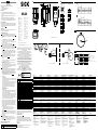 1
1
-
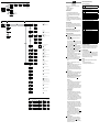 2
2
-
 3
3
-
 4
4


in altre lingue
- français: SICK ML20 Markless Sensor
- español: SICK ML20 Markless Sensor
- Deutsch: SICK ML20 Markless Sensor
- português: SICK ML20 Markless Sensor
- 日本語: SICK ML20 Markless Sensor
Documenti correlati
-
SICK PS30 Pattern Sensor Quickstart
-
-
-
-
-
-
-
-
-
