CAME ATI 24V Installation and User Manual
- Tipo
- Installation and User Manual

ATI 24V
{n
:
._)
,,
'g
- Y/n
ITr"[/l
I.r=*I
w_-
YY
C€
t-l
l------ll
ICAMEI
CANCELLI
AUTOMATICI
\J
,-
J.
;":
!
Manuale dtinstallazione
e
d'uso
lnstallation
and
Userts
Manual
ml
NIUZ
zztsi
Manual de
instalación
-=
Ydeuso
-
"""":fltì'1ft,j3t:sl
I
Installatie- en
r
Gerbruikershandleiding
r
,"[i:l1i.'g;î:ixl$ -

É-_
CAME
O
senre ATI I Allsrnres I senre
ATI
Doounìer?taaìooa
l
TeÈnica
l
rev. 4.8
a8i20a2
0c*ur
CAT{CELLI
AUÎOMAÎICI
1 1
9049-1
Ail
CANCELLI AUTOMATICI
:ììi,iri-tÌirif!:ìl$f.i\..,!.8îi
tii*:,r#i;Étiia+1.{rì.ijìB-;J.,;ri::iiiji:iÈ+ìÈi}.ììrì:ì!!ÉAt1jí,JÌ4miii*ir
ìi-1-1.r11ìi:Îrì:.::*1.1
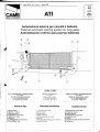
Automazione esterna
per
cancelli a battente
External
autamatic
opening system
for wing
gates
Automatizacion exterior
para puertas
batientes
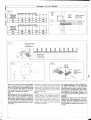
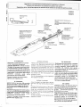
Ca_vi_diqellega.mcn!s...m.ierein!e-rf.u_t!_o-r_ì:
5x1mm2
C av.i d i.
jr-llne_n
!€lai_o_ne-m9lsr_e-;
2 x 1,5
mm2 fino a 20 m;
2 x 2,5
mm2 fino a 30 m.
W-tingfattttiercslytl'c.tes.,
5 x lmnr
P,awe-rwites-tp-,nplot
2 x 1,5 ntmt up to 20 m;
2x2,5mni'upb3Am
=Cg.ble.s_-de__ssner.t_ó._n-ni_crq!n!gl.Iu-p!_o.
jqs_l
5x1mmz
eébles,,de,,a.ljmenlac,i_glt-molo_!.1
2 x 1,5 mm2 hasta 20 m;
2 x 2,5 mm2 hasta 30 m
lmpianto
tipo
1) Moloriduttore
2)
Quadro
comando
3) Ricevitore radio
4) Fotocellule
di sicurezza
5) Selettore
a chiave
6) Antenna
7)
Lampeggiatore
di movímento
8) Trasmettitore
radio
Standard
installation
1) lrreversible
gear
motol
2)
Control
panel
3)
Radio receiver
4)
Safety
photocells
5)
Key-operated
selector switch
6) Antenna
7) Flashing light indicating
gate
movement
B)
Radio
transmitter
Instalacion
tipo
1
)
Motorreductor irreversible
2)
Cuadro de
mando
3) Radiorreceptor
4) Fotocélulas de seguridad
5) Selector a llave
6)
Antena
7) Lémpara intermitente de
movimiento
8) Transmisor

a
o
t:a.
{
ù
a
tu
ÎJ'
J
(,
2.
uJ
o
z,
J
I
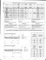
Caratteristiche
tecniche
-
Tecnichal caracteristics
-
CaracterÍsticas
técnicas
i
l--t
Dati rèlativi ai valori
di alimentazione nominale
e a
condizioni di apèrtura standard:
(R)
Reversibile;
*
Servizio intensivo;
"*
Regolabile
mediante
quadri
comando CAME
Deg-c:zroHE:
-
Progettato
e costruito interamente
dalla CAME Cancelli Automatici
S"p.a.
-
Grado di
prolezione
lP 54;
-
Garantito 24
mesi
salvo
manomissio-
ni.
Dala tefers
tù núninàl
pawer
supply
conditiúns ol aperlu|e;
(R)Reversible;
'
Heavy
duty cy.:le:
..
Can be adjùsted
using CAME cúnlroi
panels;
DEseaLp_teti
-
Designed
and constructed
entirely
by
CAME Cancelli Automatici
S.p.a
-
lP54
protecting
rating:
^
Guaranteed for 24
months,
unless tam-
pered
with
by
unauthorized
personnel.
and
standard Datos relativos
a
los
valores de la tension
nominal
y
a
las
condiciones de apèrtura
esténdar:
(R)
Reversible
*
Servicio inlensivo;
'*Aiustable
mediante los
cuadros de mando
CAME
Dcse.runeÉNi
-
Disefrado
y
fabricado
enteramente
por
CAME
Cancelli Automatici
S.p.a
-
Grado de
protección
lP54;
-
Garantizado
24 meses,
salvo manipu-
laciones.
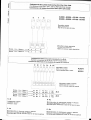
MOTORIOUTTORE
GEABMCTOR
MOTORREDUCTOB
PESO
vvF6HT
PESO
ALIMEIiTAZIONE
P{IL4/ER SUPPLY
ATIMENTACIOIi
CORRÉNÎT
NOMINALE
NOIIlINAL
AJíìNINT
c0RRtEl'tTC
NOMINAL
POTENZA
POWf R
POTENCIA
INTERMITTENZA
tAv0R0
DIJTY
CICI,E
INTERMITÉNCIA
TRA8fuO
RAPPORTO
DI
RIDUZIONE
REDUCT|OîI BATIO
RTTACION DE
REOUCCION
SPII{TA
PUSH
EMPUJE
fEMPO
CORSA
TRAVE!. TIMI
TITMPO
DE
R:C0RRt00
CONDENSATORE
CAPACITAR
c0N0EilsA00R
43000
10
Kg
230V
a.c.
1,2 A 150
W
5OYo
1136
tf
400 +
3000 N
18s
10
pF
43006
2€$
A3024 8,5
Kg
g4V
à.c. 104
120 w
*18
s
A3100
{R}
9,5 Kg
230V a.c.
"1,24
15U W
5{l%
19s
1{l
yF
43106
{R}
28s
A50tx)
11 Kg
230V,,a.c.
1|-,24
15CI W 50o1o
32*
10
pF
450CI6
45s
45024 9,5 Kg
24V a.c. 104 130
W
**309
4s100
{n}
10,5 Kg 230V a.c"
1,2 A
1S0 W
ffiú1"
32a
10
pF
45r06
{R}
45$
l
I
i
i
I
I
i
._
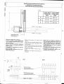
Misure
d
ingombro
e lirniti.d'impiego
/ Overall
dlmensions and use Íi.niefs
/ Oimen*iones móximas
y
lirnitesde
empleo__l
43000/A3006-A31
00/431
06-A3024
LARGHEZZA
ANTA
WIDTH OF WING
ANCHO HOJA
PESO
ANTA
WEIGHT
OF WII,JG
PESO HOJA
m
KS
2.00 800
2.50
600
3.00 400
LARGHEZZA
ANTA
GEWICHT
ANCHO
HOJA
PESO ANTA
GEWICHT
PESO HOJA
m
KS
2.00 1000
2.50
800
3.00
600
4.00
500
5.00 400
T
lco
iRl
+-
45000/A5006-A51
00iA51 06-A5024
f-
a :
..2-
,,..,
L :f
I

l_
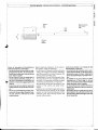
Controlli
i
-
General cantral
-
Controle*
Battuta d'arresto
Gate stopper
Tope
J
C'
\2
A.
ut
tlt
2
J
<,
z
ltt
o
z
g
I
+
cl
Y
'/a
v
t
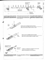
Prima di
procedere
all'insiallazione
dell'automatismo,
controllare:
-
che la struttura del cancello
sia ade-
guatamente
robusta, le cerniere sia-
no
eff
icienti
e
che non vi sia altrito
tra
parti
fisse e mobili;
-
che la misura C non sia superiore
al
valore indicato nella
Tab.
3,
pag.
4. ln
tal caso
è
necessario intervenire sul
pilastro
in modo
da
raggiungere
tale
misura:
-
il
percorso
dei cavi elettrici secondo
le
disposizioni di comando e sicurez-
zai
-
che ci sia una battuta d'arresto
mec-
canico in chiusura
(ben
fissata al suo-
lo)
per
evitare l'ollrecorsa anta/
motoriduttore.
Cerniera
Hinge
Bisagra
Before beginning
installation of the
automa-
tîan system,
check the following:
-
the structure
of the
gate
must be suffìciently
strong;
the
hinges must function efficiently
and there
must be no frlctian between
the
moving
parts
and
fixed
parts;
-
measurement
C must
not
be
greater
than
the
value
shown
in
Tab. 3
(page
4). lf this
is
the
case, it
is necessary to modífy the
pillar
sa that this
measurement cor-responds;
-
the
electrical wìring
path
according
to
the
position
of the
control and safety
instru-
men(5;
-
presence
of a mechanical
gate
stop
(secu-
rely
anchored
to the
ground)
in the clased
positian
in order to
prevent
Í.he
gate
and
the
reductian
gear
from moving beyond
the
correct ctose
position.
Antes de
proceder
a la
instalación
del
automatismo,
controlar;
-
la estructura
de la
puerta
sea lo sufi-
cientemente
sólida,
las bisagras sean
eficientes
y
que
no haya rozamiento
entre
las
piezas
fijas
y
aquéllas
móvi-
les;
-
la medida C
no sea superior
al dato
indicado en
la Tab.3,
pà9.
4. En tal
caso, es
necesarioactuarsobreel
pilar
hasta alcanzar
dicha
medida;
-
el recorrido de
los cables eléctricos
según las disposiciones
de
mando
y
seguridad;
-
la existencia
de un
tope
para
el cierre
(bien
fijado en el suelo)
para
evilar
que
la hoja/motorreductor
llegue
més allé
de lo requerido.
%tu

J
o
12,
É
ît
u
U'
J
(t
z,
UI
o
J
I
4
{
APERTURA
OPENING
ABERTURA
A
mm
B
mm
C max
mm
E
mm
90'
130
130
60
7N
120"
130
110
50
720
m
A30001A3006
-A31
00iA31
06
-43024
Pilastro
Pillar
Pilar
Den
hinteren
Búgel
mit
der entsprechen'
den
Klemmplatte
(Abb.
1) unter
Einhaltug
der
MaBe
A und
B
(Tab.3),
und
zwar
dem
Achsenabstand
zwischen
zentraler
Búgel'
bohrung
und
Torangelzaplen,
am
Torpfei-
ler befestigen.
Der
hinteren
Búgel
ist
mit
einer
Reihe von
Bohrungen
versehen,
um
eine
Anderung
des
Toróffnungswinkels
zu
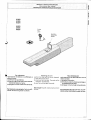
Applicare
al
pilastro
la
piastra
di
fissaggio
con
la
staffa
di coda
(fig.
1)
rispettando
le
quote
A e B
(Tab.
3)
tra
l'asse della cerniera
e il foro centrale
della staffa.
La staffa
di
coda è dotata di
ulteriori
forature
per
varia'
re l'angolo di apertura
del cancello.
N.B.:
aumentando
la misura
B diminuisce
I'an-
golo
di
apertura con conseguente
diminu-
zione della
velocità
periferica
e
aumento
della spinta motore
sull'anta.
Aumentando
la misura A aumenta
l'angolo di apertura
con conseguente
aumento
della
velocità
periferica
e diminuzione
della spinta
moto-
re sull'anta.
Attach the
fixing
plate
and the
rear bracket
(fig.
1) to the
pilar
abserv'ing
measurement
A and
B
shown
in
Tab. 3, between
the hinge
pin
and
the
central
hale in the bracket.
The rcar bracket
is
equipped
with additional
holes to
change the
open-
ing angle of
the
gate"
N.8.:
iÍ
nteasurentent
B
ts
rncreased.
the
opening
angle
is reduced.
This therefore
reduces
the
peripherat
speed
and
increases the
thrust
èx-
erted
by the
mútor on the
gate.
lf measttrement
A
is increased,
the angle
af apertLtre
is in'
creased,
This therefore
increases
the
periph-
eral speed
and
reduces
the thrust
exerted
by
the
motor on the
gate.
erlauben.
Wichtig!
Beachten
Sie bitte,
daB
bei
Erhóhen
des
MaRen
B der
Toróffnungswinkel
und
dem-
zufolge
auch die
peripharische
Torlauf-
geschwindigkeit vergróBert
und der
auf
den
Torflúgel
ausgeúbte
Motorschub
re-
d uziert.
A5000/A5006
-A51
00/A51
06
-45024
APERTURA
OPENING
ABERTURA
A
mm
B
mm
C
max
mm
E
mm
90'
200
200
120
920
'130"
2W
140
70 920
Piastra di
fissaggio
Fixing
ptate
Placa de
f iiación
HxHàHflHIHIH3##*HiHI
Staffa
di coda
Bear
bncket
Soportè
rasero
+
B
+
Snododi
coda
Rear
iaint
Articulacion
trasera
I.l
I
i
I
-J
-a

A cancello chiuso
applicare sull'anta
la
piastra
di
fissaggio, accertandosi
che
la
staffa
ditesta sia
in
asse
orizzontale
con
la staffa
di coda e
rispettando la misura
E.
Dado
M8 autobloccante
M8 locknut
Tuerca M8
de seguridad
N.B: è consigliabile lubrificare
(con
gras-
so
neutro) la vite
senza fine e
la
boccola
al momento dell'installazione.
Piastra di
tissaggio
Fixing
plate
Placa de Fijación
Spessore
Tllickness
Espesor
J
o
rZ
(tt
r!
E
g
J
(5
2
u,
z.
s
J
Livellare
la staffa
Leve! the baket
Nivelar el soporte
+j
Staffa di
testa
Front brackeî
Soporte delantero
With the
gate
closed, attach the
f ixing
plate
with the
front bracket to the
gate
wing.
The
anchor
plate
must be horízontally aligned
with the
rear bracket and
measurement
E
must be abserved.
Con
la
puerta
cerrada,
incorporar a la
hoja la
placa
de
fijación mediante el so-
portedelantero,
en línea
horizontal conel
soporte
lrasero,
respetando la medida
E.
(,'^
Stelo
Rod
Véstago
Svitare
le due viti di
fissaggio del carter ed estrarlo.
Retnove thje two screws
which
hold
the
casing in
position
and remove the
rod
Aflojar los dos
tornillos de fiiación del
eérler
y
sacarlo.
Svitare
le
due
viti di fissaggio dello
stelo ed estrarlo.
Hentove
thje
two screws
which hold the
rad in
positiort
and rcmúve
the
rod.
Aftojar los dos
tornillos
de
fiiación del
véstago
y
sacarlo.
é
A
Vite senza fine
Worm-oear
r"rnirrJ"lnln
Procedere al
montaggio del motoriduttore
alle due slatfe'
lnstall the
gear
motor on the twa brackets
Montar el
motorreductor en
los dos soportes.
MBxl 0
N.8; use neulral
grease
to
lubricate the
wormgear
and
the washer at the
mamenl
of installation.
Nota: es aconsejable
lubricar
(con
grasa
neutra)
el tornillo sin
fin
y
la
arandela
en
el momento de
la
instalación.

J
o
1Z
a
tn
rrl
at
J
(,
z,
u,
ol
z,i
<l
J]
I
=l
I
I
I
l
I
l
l
43000
-
43006
-
A3100
-
A3106
45000
-
45006
-
A51
00
-
A51
06
Morsettiera
motore
Motar
terminat
block
Caja
de
bornes para
el
motor
Morsettiera
scheda
elettronica
Te
nni
nal
board
electrortics
Tablero
de
bornes
tarjeta
electrónica
I
Motore
_
li,4otor-
Moteur
1
.-*è
Motore
-
Molor
-Moteur
2
-->
Gofregamenti
a*esehede
erettronicheTAs
r7A4
r,.A5
rZM.
Cannections
tú
the
ZA,A
-
ZA4
-
ZAS
a,
iM;;;;;;;;;;;;;;
conexisnes
a
fa
rariera
etectrónica
zaii
i'il'il'ts;i;;
jSffegalenri
eteilrici
ai
quadri
comando
ZL14
a
ZL.t9
=:?::::connections
to
the
ZLt4
ar
ZLte
controt
panets
Conexiones
eléctricas
en
los
cuadros
Oe
manOo
ZL14
ó
ZLIS
Ra
l,u1
)l
tel
'l
l
\
I
t,
Morsettiera
motore
Motor
terminat
block
Caja
de
bornes
para
el
motor
zLl4
Morsettiera
quadro
comando
Control
panel
teffiina!
bloch
Caja
de
bornes
cuadro
de
mando
430?4
45024
Motore
-
Motar
-
Moteur
1
Motore
-
Motor
-
Motew
2
N1
*ttz
Ml
2
M22
Fal
Rc1
z
Fa2
Rc2
2
Ral
RaZ
Motore
-
Mator
-
Moteur
1
Motore
-
Motor
_
Moteur
2
N-M
Collegamento
motore
L;annectron
to
motoÍ
Conexión
motor
F'
Fa
*---*-+
Nl
N2
Ml
C
Fat
Rcl
C
Ral
M2
C
Fa2
Rc2
C
Ra2
zLl9
M.icrointefruttore
di
fínec,
#[f
3'#[??
j[?Íix#l,gl,j:r,,*;g"Tr.,""::';:""..aperrura
R-Rc
Microínteruttore
di
rallentamento
motore
in
chiusura
Mtcraswitch-deceleration
of
molor
ort
closui
Microinterrupror
deceteraciélHi;r*;;";
rase
de
cierre
H-Ha
M,icroínterruttore
di
rallen
tw{)ros.wîcn-deceteta,on"i'#frinyr1îninapertura
rvucrotnlerfuptor
deceleración
motoi
en
la
fase
de
apertura
I.
I

ts---
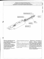
Regolazione rnicrointerruttore
$îOP
in apertura
Adjusting
fire SIOP
micraswitch
fot the aperture movement
Regulacion
del microinterru$toi
de sTOP en:la fase de
apertuia
Asta
porta-microinterruttore
Suppod
plate
mícroswitch
Chapa
porta-microinterruptor
Slitta azionamento microinterrultore
M ic rosw ilch
act Lr atio
n
ru
n n
e
r
Corredera accionamiento microinterruptor
Vite
di fissaggio
Fixing scrcw
Tornillo
de
filación
Gruppo microinterrutore
Micraswitch
utlit
Grupo
microinterruplor
Madrevite
Saew-nut
Tornillo iuerca
Sbloccare
il motoriduttore
e
portare
l'anta in
posizione
di apedura
massima
desiderata.
Svitare le
viti di
fissaggio
del
gruppo
microinterrutore.
Far
scorrere
il
gruppo
microinterruttore
sull'asta
porta
microinlerruttore
fino
a raggiungere
l'inserimento
dello
stesso mediante
contatto
sulla
slitta azionamento
gruppo
microinterruttore.
Fissare
il microinterruttore
agendo
sulle rispetlive
viti.
-
Release
the
gearntotar
and ntave
the
door to the maximum
desired open
position.
Loosen
the
f ixing
screws
af the
micraswitch
unit" Slide the micraswitch
unit along the microswitclt-support rod
until ít is inserted
by contact an
the
microswitch unit
actuation runner.
Fix
the microswitch
by tightening the
respecttve
screws.
-
Desbloquee
el motorreductor
y
coloque la hoja en la
posición
de
apertura màxima deseada.
Desenrosque
los tornillos de fijación
del
grupo
microinterruptor.
Haga
deslizar
el
grupo
microinterruptor
sobre
la
varilla
porta-microinterruplor
hasta
que
este se introduzca
por
contacto sobre
la
corredera de accionamiento del
grupo
microinterruptor.
Fije
el
microinterruptor
apretando los
tornil
los correspondientes.
J
o
t2.
À
(t
UJ
E
2
J
(t
z
ut
c}
z
g
J
f(

o
,:e
CL
î1,
u
u,
J
C'
z,
rg
o
z.
J
ts
l
I
I
43024
4,5024
Mícrointerrutîore
di rallentamento
in
chiusura
D
ere le|atio
n n iî
| os
witc h
fo r
c lt]
s u re
Micrinterruptor
de reduccion
de la
marcha
en cierr€
Vite
senza fine
Worm-gear
Tornillo
sin fin
Slitta
azionamento
microinterruttore
Mìcroswitch
actLral
nn {u rìne
r
Corredera
accionamiento
microinlerrupîor
Madrevite
screw-nul
Tornilo
tuèrca
Gruppo
microintérruttore
di
rallèntamento
e
di stop
in
apenufa
Micrzswitch
unit far
slLrwrrld
and stopping
duting
apenilV
Grupo
microinterruptor
de
deceleración y
dè
parada
en apenura
Supportocavo
CabJe
f0ber
Soporte
paracables
Asta pona
mícrointerru$ore
Suppon
plare
mtcroswttch
Chapa
porta
microínterruptor
Madrevite
SLxerv-nul
Tornillo
tuerca
Viti
di fissaggio
f ixing
$rews
Tornillons
de Fijación
IN
APEBTURA:
Sbloccare
il
motoriduttore
e
portare
l'anta
in
posizione
di
apertura
massima
desiderata,
svitare
le
viti
di
fissaggio
del
gruppo
microinterruttori
di
rallentamento
e
di stop
in
aperlura.
Far
scorrere
il
gruppo
microinterruttori
sull'asta porta
microinlerruttore
fino
a
raggiungere
I'inserimenlo
dello
stesso
mediante
contatto
suf la
slitta
azionamento
microi
nterruttore.
Fissare
il
gruppo
microinterrultori
agendo
sulle
rispettive
viti.
Fissare
il gruppo
microinterruttore
agendo
sulle
rispettiva
viti.
IN
CHIUSURA:
portare
l'anta
a non
oltre
100
mm
dalla
battuta
d'arresto
in
chiusura
lpart-
È1.
Svilare
le
viti
di fissaggio
del
gruppo
mrcrotnlerruttore
di rallenlamento
in
chiusura.
Far
scorrere
il
gruppo
microinterruttore
sull'asta
portamicrointerruitore
fino
a
raggiungere
l'inserimento
dello
stesso
mediante
contalto
sulla
slitta
azionamenlo
m icrointerruttore.
DTJRING
OPENING:
Release
fhe
geannator
ancl
move
the
wing
to
the
maximunt
desired
apen
position,
unsctew
the
fixing
screws
of
the
deceleration
microswitches
unit
ancl
the
untt
that
controls
the
stop
during
opening.
Slide
the microswitches
unit
alona
the
nticroswitch-support
rod
unttl
it is
inierted
by
contact
on
the
nticroswitch
unit
actuati?n
runner.
Fix
the nìcroswitches
unit
by tightening
the
respective
screws.
DURING
CLOSURE:
move
lhe
wing
to no
closer
than
lA0
mnt
fram
the
end
stap
during
closure
(delail
B)
Unscrew
the
fixing
screws
af
the
group
decelerction
microswitch
during
clasure.
Slide
the
mlcraswitclt
unit
alana
the
microswitch-support
rod
untrl it
ts iníerbd
by
c0ntact
on
the
microswitch
unit
actuatiotl
rL!nner.
F'ix
the
microswitch
unit
by
tightening
the
respective
screws.
EN
APEBTUFIA:
Desbloquee
el
motorreductor
y
coloque
la
hoja
en
la
posición
de
aperlura
méxima
deseada,
desenrosque
los
tornillos
de fijación
del
grupo
microinterruptores
de
deceleración
y
de
parada
en apertura.
Haga
deslizar
el
grupo
microinterruptor
sobre
la
varilla porta-microinterruptor
hasta que
este
se iniroduzca
por
contacto
sobre
la
corredera
de
accionamiento
del
microinterruptor.
Fije
el
microinterruptor
apretando
los
tornil
los
correspondientes.
EN
CIERRE:
Coloque
la
hoja
a no
màs
de
100
mm
del tope
de
parada
de
cierre (det.
B).
Desenrosque
los
tornillos
de
fijación
del
grup0
microinterruptores
de
deceleración
en
cierre.
Haga
deslizar
el
grupo
microinterruptor
sobre
la
varilla porta-microinterruptor
hasta que
este
se introduzca
por
contacto
sobre
la
corredera
de
accionamiento
del microinterruptor.
Fije
el
grupo
microinterruptor
apretando
los
tornillos
correspondientes.
Regolazione
microintèrruttori
di rallentamento
in
apertura
e in
chiusura
Adiusting
the
deceleration
microswitches
for
aperture
and
closure
Regulación
de los
microinterruptores
de reducción
de la
marcha
en
las
fases
de
apertura y
cierre
Batluta
d'arrèsto
Gate
jafib
Tope
.\
.b
F
t
O
rp
z
---
ió l
I

Sblocco
a chiave
personalizzala
Personalized
key release
Desbloqueo
medíante
llàve
person
alizada
43000
43006
43024
45000
45006
45024
Per
sbloccare
l'operazione
di
sblocco
va
efÌettuata
a
motore
fermo:
1)
sollevare
lo
sportellino;
2) inserire
e
girare
la
chiave
che istanta-
neamente
sblocca
l'anta;
3)
spingere
o
tirare
l'anta
manualmente.
Per
bloccare
nuovamente
l'anta
è sufli-
ciente
reinserire
e
girare
la
chiave
Sportellino
Access
door
Portillo
Releasing
the unit
para
desbloquear
pertorm
this
step
witlt
the motot
stopped:
esta
operación
se debe
efecluar
con el
Chiave
Key
Llave
E?r-
fr!l \
f.::r.t I
9é;t
18
-é-
I
)
raise
the access
door
2) insert
and
turn
the key.
released
imnediately;
3)
puslt
or
pull
the
gate
ntanually.
The re-lock
the
gate,
simply
inseft
and turn
the key.
motor
parado:
The
gate
will
be 1) levantar
el
portillo;
2) introducir
y
girar
la
llaveque
ensegui-
da desbloquea
la
hoja;
3) empujar
o tirar
la
hoja manualmente.
Para
bloquear
de nuevo
la hoja,
es
sufi-
ciente
volver
a introducir
y
girar
la llave.
J
C}
\2
È
a
l{J
T
2
J
(t
z
UI
o
z
s
J

-l
oll
'z,
lI
aìl
(all
uril
It
l
-l
ai
J]
(.'l
z.
1
UI
I
l
l
ol
z,
l
.{t
Ji
<l
FI
l
l
Esterno
-
OLrtsicte-
Éxlerior
-
Rilevare
le quote
A
e
B
(Tab.4).
-
Fissare
la
staffa
di
coda
integiandola
con
una
slaffa
supplementare
e
applí-
carla
al
pilastro.
-
Aprire
il
cancello
{max
90.},
rilevare
la
quota
E
(Tab.
a)
e
fissare
all'anta
la
staffa
di
testa.
-
Procedere
ai
collegamenti
elettrici
come
da
figg.
1
e
2;
-
Riposizionare
e
regolare
il
micro
inler-
ruttore
di
apertura.
*
r---1-
tl
fntèrno
-
lnsoide
-lnterial
-
!!e.as.ure
the
lenght
of
"A"
and,B,,
lsee
Tab
4).
-
Attach
the
rear
bracket
together
with
a
sttpplementary
bracket
and
fasten
both
to
the
calumn.
-
Open
the
gate
(maximum
g0,')
and
mea-
sure
"E"
(see
Tab
4),
then
fasten
the
front
bracket
t0
the gate.
-
Cannect
the
wiring
as
shown
in
figs.
I
and
2;
-
Reposition
anrt
adjust
the
opening
mi-
croswitch.
statta
supptementl
S u
{-tp
I
em
e nta
ry
b rac
ke
I
Soporte
adicional
-
Determinar
las
medidas
A
y
B (Tab.4).
-
Fijar
el soporte
trasero
en
el
pilar,
iras
haberlo
integrado
por
oltro
adicional.
-
Abrir
la
puerta
(max
90.,),
determinar
la
medida
E
(Tab.
4)
y
filar
en
la
hoja
et
soporte
delantero.
-
Proceder
a las
conexiones
eléctrícas
de
acuerdo
con
tas
tigs.
1
y
Z;
-
Coloque
nuevamente
y
regule
el
mi_
crointerruptor
de
apertura.
Mi
lf
,
'.U\----r
+
I
Fis'l
Fig.2
YlTilil
\
v_,-1--'------,'
i r il I
r.r
M
F
Fr
Rc
R
Rn
, ra ,,l-,, ,!,.
,.1
L
'
ià[
ialÉa)r
tà
iei
)àt,
)e
+
\U/ ala),Fzik)
Morsettiera,norore
---+...
(t
o aj
o
,r
i
"".*
H
lz
..r'atr,r---
3';:';:1r#i::12r",*.,",-''n'-'-n
t(al
1i
'1'
"ii
V4l
i+
l?:l
l:::o:-
u v
w
i
i I i
i
] i
!
:
u
Morore-Moror-Moreurl-*--
--/:--N\iffi?
îH?--
-!
r
f
ry
Morore-ny'oror-Moreur2-
S,b
Mz
F
Far
Rcz
Rz
il
(
Massa
LJ
Li-;
-!;:l
llll
illl
i
i I I
i
I
Groundiuvwiillir
rierrai
i-illiii
,{
I
._l-::,_f.:,---,
itl
li,1,,',jP*;,Tm:f;::f
ii I
i ij-j
;,-;
rl,
,i;
J^,
l,
f-----calaoeÀornescuadrodemando
---*
' i i I l
, ,iillFf
,.t1Hf
1,rl
i
fil=ti ,'r-' n5 n5
nl.J
rú ÉliLr; rn l'
,
-,
,,
tJ
l'-.
-
]L.lrr|-i
I
,'
+
u
v
w
,i-M^^r6-,^^.
.)L-r+++1,'
'L-JL!t]lFi
'
I
t-,.f
Applicazione
per
aperture
verso
l,esterno
Applicat
ion
for
o
utsid
e
ape
rtu
re
Aplicación
para
apertura
hacia
exterior
43000-3006
3100-3106
3024
45000-5006
5100-5106
5024
A
130
mm
200
mm
B
130
mm
200
mm
E
720
mm
920
mm
L
.T
li
)-t),

MANUTENZIONE
PERIODIC
A I PERIODIC
MAINTENANCEI
MANTENIMTENTO
PERIODTCO
-
Lubrificare
la
vite
senza
fine
e i
perni
di
rotazione;
-
Controllare
le
vitidifíssaggio;
-
Verifi
care
I'integrita,
dei
cavi
di cottegamen-
to,
-
Lubricate
he
wonn
screw
and
the rotatino
pins;
-
Ceck
the
clatnps
screws;
-
Ceck
the
connxtion
cable's
soundness.
-
Lubrique
el tornillo
sin
fin
y
los
pernos
de
rotación;
-
Controle
los
tornillos
de
sujeción;
-
Controle
el
estado
de los
cables
de
co-
nex6n.
-l
I
lr
tv
l'z
J<
lÀ
In,
l-
I
t'
2
I
o
z.
$J
o
z,
s
J
É
t
I
L_._
L

iK
I Rappreseillanti{leila
CAME
Cancelti
A0tomatici
S.p.A.
via f',,|arîrri
deila
Liberiè,
lat
31
o3oDoss.in
ili
Casi.ir.
Treviso
lTALylel
ír 39)
04P2
4940
laxl+39j
04ZA
4941
rnteriel:
!r,r!w
cane_l(
_
e_rnaji:
;nÍoliicatrie
I
DtchiaeDa
sailo
la
prcptia
respansabttttà
che
i/!l
oro(tottù/,!tjètlonrinaîo.,i
. .
sorìo
ccnfoffiti
eilct
(Jispasi:pni
tegislative
Nazrcna!i
ctte
truspongoa(,
le
seguèùti
Ditelilve
Ca n1
L! n tta
n
e
(dove
spect
ficatane
nîe
ap
pt
ttabtl
|
).
lJ
nÈrr
vA
i,4^c.ilN:
gBt3TiCE
D|FErîiva
f]alsa
f
IN-:roN[
73./23,/{]ÉÈ,
93l6BiCE
E
DrBF'
:,vA
(lor,tFAr
6 ra
Et ErtÈiìMA!ilirca
ti9/33€;/CEF
- g}i:i
1 iC)EÉ
LrrFEr,vn
R&lTE
1999/SiCÉ
Data
de!tx
p11,5sn1s
4,ctuaraz;onp
6). 12;;gg1
lnolke,
dich
jara
cho
il/t
Í,rodano,,i,
,aù
t'lxd'dzu'te
u/')
tzloul
delle srro! Fnt)
(,,n,n*,",,
^^-,,^
,,"-_..,.î.!j!,
della
presenle
dichrarazione,
sono
cosîtutt/
net
ilspotiú
del le
sègue
n
lt
{yinct
patí
notrne
a nr"r,ín,zzttte
Ef'l
292
i*HíÈ
1,,8
2,
EN
12453
EN
12445
Ér'.t
60335.
1
Ehi
60204
.
1
Éf'i
50081
-1É2
El'j50082.1É2
AVVERTENZA
IhIPARTANTE
!
E
-vietaio
metterc
in
seruízio
iri
ptodo{io/i,
oggetto
deila
prèsente
tJlcl|eraziotje.
piln1a
dcjl
&Ítpiotaùiento
è,,o
incerporanènta.
,n
totajà
contototità
aIi
aìi[urirliíoan
air"ntun
lr!acchrìe
98,i3VCE
l, I rrna
tle i
Rapprct
se
nta rìli
HE
SPON
SAT}
i
L E r.
ECN
ICO
stg
cannii,aUJa'n-"
PRÈstaE^ttE
i ., , ,
t'g
Peolu
Me1y2zt'
.,.
.ti
;,.,
)-^
t,
.
<'
<'* ^.-
Íi o
rnilz,r
cEt
ùtAaa.i
ùAF,o
fir,.
.u.t'.t.,
:-at
L-..,r'.1L4.
cr,
.rÀÈ
:it
w
.-al
u
..,.rits
x.:
5,Or.HÈiz^
NEaìit
AFeAHETi:cfti
n!
!sri
trofi!sircrj
b:cL'ìiZZ?ì
DEi
ft4Oci
tlAF:O
CouirAi
lir,LiT!
EiE
Í ì
io^rariN!l
{::A
CoMirAi
B,LiTÀ
EiE
i I
so[iariN!
I ia
A.
DICH|ARAZ|ONE
oel
pnÉnnlffi,r.rrE
\iDhe
úèì
MAN
u FAcru
RER;S
oec
rffi
r,r
z,,cE
Encrosed
with
the
technicardocumentatior
lthe
origiraìnfirGJ1l^ration
is
avairabre
on
rcquest)
o"t"ottn"Gffi]lfffrlffit
I).Ò
a\i ft
ì é\7
i d :
I tu
t
rJ
a i i c h
ú
The
representalives
of
CA&tE
Canceili
Automatici
S.p.A.
viar
À4itrlr.i
della
Litrerta
15
31(i30
a)osson
.li
Casier
-
Treviso
-
lTAl.y
lel
ir39)
0422
4940
-
lax
(+39)
0,i22
494
1
Interiret:
!!v/!v
came.il
É_nlaii:
Hereby
declare,
under
theî
own
rcspons
ibitíty,
that
the
product/s
cailed
...
compry
wtth
the
ltalian
National
Legal
prcvisions
that
transpose
the
lollowing
Communíty
Directives
(where
specíficatty
appticaòiis1.:-
' '
Idactsr\É?,/
DrF:c-lrvE
99,,37lCiE
Low
VoLiAGE
DtHÉoi,v: 7il2-llEEC
,
33159,16gg
La-:
j&t.d::lrIr,::
CoUt,lr,iii ru
Dtfirr::Irr
gSl:ì30,/[taC
.
92/31/ÉEC
R&fîÈ
DrqÈtrirr
19_o9i
atlcF
Drneci
vr
:,:
Mi.ì
lrA:ì
9B/37l,tlF
P
".,
'"
. B-
,I
r
..
.,íì
2r.CLb
e.;
6d
CE
E
iilll
-''ì
;^Îi;]nìr
u, F
' -
:'ó
,c '
a
8e'336
cEÉ
(2,r
cÉL
Also,
they
futthermore
represent
and
watrant
that
the
product/s
that
are
the
suqect
ot
the
present
Dectaratíon
are
manutactured
in
the respect
ot
tne
tio*iij
iaìniìràir-irea
prorisiors,
Èli
292 Fxnr
1
^rrir
2
FN
12453
EN
124,15
EN
603Jì5-
1
EN
60204
-
1
EÀi
500B1
.
I
Arf
2
ÈN
5008?
,
1
^,irr
a
N4aorjtNEl
ì;
5nt
I f
y.
lritrt;:trirDI,
icfyrùjIFciAi
aNo
crf
FB at
i
]ijtf
jit
uF(ìi1{!rsf,1s
l',',r
,;,ar
,:',.r.,F;.
a.
a.t.
riLl
.. rr_
vL.,.;,...,r.
ùt
!:r
,"
,,:
:^r,a
r,..t..
c.
o
(1L
.L.
l'.41,:
t,,rEFu
sAar.
Ei.Er-rÉoMActE
t rc
CovreletL,t
y
Eit,:.rltr,lli:;le
i0
(loupaT
ptL
rr
IMPORÍANî
CAUTION!
l:i::1t!!!en
to
Tirket/use
pnducî1.sîhat
ar_^
îhe
subject
oi
ihis
cieîiaratian
{,ercre
conlpteîng
arid,
or !ncatporating
them
in
total
cofttptiance
with
tne
fjrovisions
ot
Uacniiiirr)
nirective
g|l:t7.i(:E
Signalu
rcs
of the
if
eptese
ntatir.és
TECHNIl}AI
MATNAGER
I
Mr.
Giànrt
Micltetan
i
il. i
íi,i.
,!:'i.."
1{.1.
-.
.
MANAGÍNG
DIRECTOfr
Mt.
Paolo
l,'leluzzÒ
"i"
ú
"":t'i:::::--
**
:5-p:131!a133!lent;lo
a.)il
tte
ptù(trît,
t5
,àvr.t.jb!ì
on
îtttiest
DEC
DEL
FABRICANTE
on
esta
d'ponibre prcwa
peticrcn)
re"ffiot
Los
Representantes
de la
compaòia
Los
ptoductos
obieto
de
esta
decraración
estàn
rabricados
rcspetando
ias
siguientes
normas
CAME
cancelri
automatici
s.D_A.
amontzadas:
via
L4ariiri
(iejlú
L.ii,erta
1
5
310.1,)Dossondic;iierltrevrso-ttnL,y
EN29r?aFrEr"i2.
1er
(.i39)
0421
4940
.ìo*
r*sòj
joze
or*,
ÈNt
124s3
,rrcr
cr.
!!s/!v
Éame
i,
-
a-ni,i,
,nlo-o"ur"
,t
[-:N
12445
Decta^nbarosuresponiaoi,aaolàeureproducto/sdenominado/s...
Eli33;31,1
EN5()081-lriì
EN50082,rE2
AVVE
RÍE
N
ZA
I M PO
fr TA
Nî
E !
Està
prohibidonacq
uso
dÈ
el,,(,s
tiroduLlo,,s. objetúCe
ia
presenîe,leclaea.iórì
an*súe
tlotrlptetaia
s
y,rù
utcorpÒtarlo./s
eù
iùiai
Lyntùrnidaú
a lzts
disposicionès
de ià
fri,:""iiàiju
llnqriFas
eBiz,CE.
FirfrÉ
iie
los
Represeilanîes
RE
S PA
NS
/\B
i.E
T
E
C ù1 I
C
O
St
(;ianni
ttichìeian
,l
ii
/
,;
ìii.,,t'!,:.1i:...
;:,,....-...
PRESID[:Nr
E'
Sr.
paoiD
lient!z;t)
L'*'ei
"::':íl'"'i:::*
-
- *--
43000.
A3006.
A3100.
A3i06.
A3024.
A31
24
A5000.
A5006.
AS100.
A5106.
A5024.
A5124
D001
.
H3000.
LOCKB1
.
LOCK82
,; ::J:::L:;:,Xi,!;::i:f*,!:z:í::lr::,:;::;:";î,:::,que
trasponen
tas
sisuientes
lH)clYSn
teyi:::":i:\'it!(:a
dè
tús
t)ttcluctùs
està
disponibte previa
penaon
li:',]
J
f,i:j";:1",,#Íl
"TlÍ:,iJló.,,1"8,,,'lf
;:lr;";l;;1,,,r;;ì ":
;
Alj
ta!3
cli.tckècj
tu!i1
.iccepteú
Îor
aîv etr.t
iììiiìill:;iii:i:.Ìii!ìr:i!!):1.;t:diiti:lii::+iÈuiiili;:iiÌ;trÌjii!ì!titiiiiijij::iiii:tri:iìlf,irìì::ji::
Nunrno
Vrnx
I
B0ù
2ssst0
lV$
www,
ca
m
e.
it
E
"
Lrttr-
SilltM^
aìLrAJlA
\ijtt)
iiastjttf]!
nn ];èbih!j1
):,
lodos
lo$
dato:.
olrslante
no
nos
oftlt9tone5.
so
nan
contlolado
con
lt
marrma
atÈnrron
l{o
responseb'ttzamos
qe
los
postbles
errores
u
IN]]ì
Ttít1t{.A
:1Y5*lT:-i'?3S3;*'
.;-
.'coiry'ro M
(Mr)
"o"'*o"i;;--
ù;;;
ilffi;
__-
i+39)
0a
2s490gBB
{r33)
01
astsosoi-J;
ir.s3ì",,, 4€rrnÀn^
-ii:::'
:::1,1rrr_:::illì-::
-r:i::1.
l::1r:i:::
::.r:..
::::
::::.1r|i::r.
. :..r:.tr
CAME
CANCELLI
AUTOI,/ATICI
S,r].A.
Dossoi,r
oi
C,isren (TREVISO)
J(+39)0422
4940
5(+39)042249a1
CAMESUOS.R.L
-.:l::""
rtoù/
vr
4orru5u5
f!
(+33)
0l
46130500
i^i;'i;;'àq+ss
s
iissi
oei
Ttlolîs
i.if,'#'îî;a;uró
oE-'dj,?lrllffi?lài
CAME(AMEHICA)LLC
-,,.
--
t tAMr(FL)
"origy?rJ,r-,.
,..
-.;r
serrerceer
{BERLTN)l
I
(*t)
sos
sssopzt
É.1
i-iiaÀs
i::::t
iJlli
*
saeeasen
Ér
(*ae)
0s isesesscB
CAME
AUTOMATTSMOS
S.A
; - .._:
_.
MADRTD
CAME
pL
SP.ZO
0____
WARSZAWA
J
J
{+34)
oer
s2gsoos
-f
{i4tiai
ds;;A
iìài
oez
836s076
E
(,4s)
ozz
Bg6ee2o
CAMFBELCì'UM
NU.
SA
LESSINES
CAMEUNITEDKINGDOML'TD
..NOTTINGHAMJ
J-
{*32)
068
33a014
É!
('32)
o$e
iàsilé
iloiu.,,un r.roouo
Èl
(+44}
01
15e
210431
L
- -a
-
 1
1
-
 2
2
-
 3
3
-
 4
4
-
 5
5
-
 6
6
-
 7
7
-
 8
8
-
 9
9
-
 10
10
-
 11
11
-
 12
12
-
 13
13


CAME ATI 24V Installation and User Manual
- Tipo
- Installation and User Manual
in altre lingue
- English: CAME ATI 24V
- español: CAME ATI 24V
Documenti correlati
-
CAME ATI A5106 Guida d'installazione
-
-
-
-
-
-
-
-
CAME FROG A Guida d'installazione
-