HK Audio Lucas nano 600 Manuale utente
- Categoria
- Altoparlanti della soundbar
- Tipo
- Manuale utente

Manual 1.0

Version 2.3 05/2013
Important Safety Instructions! Read before
connecting!
This product has been built by the manufacturer in accordance with
IEC 60065 and left the factory in safe working order. To maintain
this condition and ensure non-risk operation, the user must
follow the advice and warning comments found in the operating
instructions. If this product shall be used in vehicles, ships or
aircraft or at altitudes exceeding 2000 m above sea level, take care
of the relevant safety regulations which may exceed the IEC 60065
requirements.
WARNING: To prevent the risk of fire and shock hazard, do not
expose this appliance to moisture or rain. Do not open case – no
user serviceable parts inside. Refer service to qualified service
personnel.
This symbol, wherever it appears, alerts you to the
presence of uninsulated dangerous voltage inside the enclosure –
voltage that may be sufficient to constitute a risk of shock.
This symbol, wherever it appears, alerts you to the
presence of externally accessible hazardous voltage. External wiring
connected to any terminal marked with this symbol must be a
“ready made cable” complying with the manufacturers
recommendations, or must be a wiring installed by instructed
persons only.
This symbol, wherever it appears, alerts you to important
operating and maintenance instructions in the accompanying
literature. Read the manual.
This symbol, wherever it appears, tells you: Take care! Hot
surface! To prevent burns you must not touch.
• Read these instructions.
• Keep these instructions.
• Follow all warnings and instructions marked on the product and
in this manual.
• Do not use this product near water. Do not place the product near
water, baths, wash basins, kitchen sinks, wet areas, swimming
pools or damp rooms.
• Do not place objects containing liquid on the product – vases,
glasses, bottles etc.
• Clean only with dry cloth.
• Do not remove any covers or sections of the housing.
• The set operating voltage of the product must match the local
mains supply voltage. If you are not sure of the type of power
available consult your dealer or local power company.
• To reduce the risk of electrical shock, the grounding of this
product must be maintained. Use only the power supply cord
provided with this product, and maintain the function of the
center (grounding) pin of the mains connection at any time. Make
sure the mains outlet used provides a proper protective ground
connection.
• Protect the power cord from being walked on or pinched
particularly at plugs, convenience receptacles, and the point
where they exit from the device! Power supply cords should
always be handled carefully. Periodically check cords for cuts or
sign of stress, especially at the plug and the point where the cord
exits the device.
• Never use a damaged power cord.
• Unplug this product during lightning storms or when unused for
long periods of time.
• This product can be fully disconnected from mains only by pulling
the mains plug at the unit or the wall socket. The product must
be placed in such a way at any time, that disconnecting from
mains is easily possible.
• Fuses: Replace with IEC127 (5x20mm) type and rated fuse for
best performance only! It is prohibited to use “patched fuses” or
to short the fuse-holder. Replacing any kind of fuses must only be
carried out by qualified service personal.
• Refer all servicing to qualified service personnel. Servicing is
required when the unit has been damaged in any way, such as:
- When the power cord or plug is damaged or frayed.
- If liquid has been spilled or objects have fallen into the product.
- If the product has been exposed to rain or moisture.
- If the product does not operate normally when the operating
instructions are followed.
- If the product has been dropped or the cabinet has been
damaged.
• Do not connect external speakers to this product with an
impedance lower than the rated impedance given on the product
or in this manual. Use only cables with sufficient cross section
according to the local safety regulations.
• Keep away from direct sunlight.
• Do not install near heat sources such as radiators, heat registers,
stoves or other devices that produce heat.
• Do not block any ventilation openings. Install in accordance with
manufacturer’s instructions. This product must not be placed in
a built-in installation such as a rack unless proper ventilation is
provided.
• Always allow a cold device to warm up to ambient temperature,
when being moved into a room. Condensation can form inside it
and damage the product, when being used without warming up.
• Do not place naked flame sources, such as lighted candles on
the product.
• The device must be positioned at least 20 cm/8“ away from
walls.
• Use only with the cart, stand, tripod, bracket or table specified by
the manufacturer or sold with the product. When a cart is used,
use caution when moving the cart/product combination to avoid
injury from tip-over.
• Use only accessories recommended by the manufacturer, this
applies for all kind of accessories, for example protective covers,
transport bags, stands, wall or ceiling mounting equipment. In
case of attaching any kind of accessories to the product, always
follow the instructions for use, provided by the manufacturer.
Never use fixing points on the product other than specified by the
manufacturer.
• This appliance is NOT suitable to be used by any person or
persons (including children) with limited physical, sensorical or
mental ability, or by persons with insufficient experience and/or
knowledge to operate such an appliance. Children under 4 years
of age must be kept away from this appliance at all times.
• Never push objects of any kind into this product through cabinet
slots as they may touch dangerous voltage points or short out
parts that could result in risk of fire or electric shock.
• This product is capable of delivering sound pressure levels in
excess of 90 dB, which may cause permanent hearing damage!
Exposure to extremely high noise levels may cause a permanent
hearing loss. Wear hearing protection if continously exposed to
such high levels.
• The manufacturer only guarantees the safety, reliability and
efficiency of this product if:
- Assembly, extension, re-adjustment, modifications or repairs are
carried out by the manufacturer or by persons authorized to do so.
- The electrical installation of the relevant area complies with the
requirements of IEC (ANSI) specifications.
- The unit is used in accordance with the operating instructions.
• This product is optimized for use with music and speech signals.
Using this product with sine wave, square wave or other kind of
measuring signals at higher level may lead to severe damage of
the product.
General Notes on Safety for Loudspeaker
Systems
Mounting systems may only be used for those loudspeaker
systems authorized by the manufacturer and only with the mounting
accessories specified by the manufacturer in the installation
instructions. Read and heed the manufacturer’s installation
instructions. The indicated load-bearing capacity cannot be
guaranteed and the manufacturer will not be liable for damages in
the event of improper installation or the use of unauthorized
mounting accessories.
The system’s load-bearing capacity cannot be guaranteed and
the manufacturer will not be liable for damages in the event that
loudspeakers, mounting accessories, and connecting and attaching
components are modified in any way.
Components affecting safety may only be repaired by the
manufacturer or authorized agents, otherwise the operating permit
will be voided.
Installation may be performed qualified personnel only, and
then only at pick-points with sufficient load-carrying capacity and
in compliance with local building regulations. Use only the mounting
hardware specified by the manufacturer in the installation
instructions (screws, anchors, etc.). Take all the precautions
necessary to ensure bolted connections and other threaded locking
devices will not loosen.
Fixed and portable installations (in this case, speakers and
mounting accessories) must be secured by two independent
safeties to prevent them from falling. Safeties must be able to catch
accessories or parts that are loose or may become loose. Ensure
compliance with the given national regulations when using
connecting, attaching, and rigging devices. Factor potential dynamic
forces (jerk) into the equation when determining the proper size
and load-bearing capacity of safeties.
Be sure to observe speaker stands’ maximum load-bearing
capacity. Note that for reasons of design and construction, most
speaker stands are approved to bear centric loads only; that is, the
speakers’ mass has to be precisely centered and balanced. Ensure
speaker stands are set up stably and securely. Take appropriate
added measures to secure speaker stands, for example when:
- the floor or ground surface does not provide a stable, secure
base.
- they are extended to heights that impede stability.
- high wind pressure may be expected.
- there is the risk that they may be knocked over by people.
Special measures may become necessary as precautions against
unsafe audience behavior. Do not set up speaker stands in
evacuation routes and emergency exits. Ensure corridors are wide
enough and put proper barriers and markings in place when setting
speaker stands up in passageways. Mounting and dismounting
are especially hazardous tasks. Use aids suitable for this purpose.
Observe the given national regulations when doing so.
Wear proper protection (in particular, a helmet, gloves, and
safety shoes) and use only suitable means of ascent (ladders,
scaffolds, etc.) during installation. Compliance with this requirement
is the sole responsibility of the company performing the installation.
WARNING!
After installation, inspect the system comprised of the mounting
fixtures and loudspeakers to ensure it is properly secured.
The operator of loudspeaker systems (fixed or portable) must
regularly inspect or task a third party to regularly inspect all system
components in accordance with the given country’s regulations and
have possible defects repaired immediately.
We also strongly recommend maintaining a logbook or the like to
document all inspections.
When installing speakers for longer lasting or permanent outdoor
operation, be sure to take into account the stability and load-
bearing capacity of platforms and surfaces; loads and forces
exerted by wind, snow, and ice; as well as thermal influences. Also
be sure to provide sufficient safety margins for the rigging points
used for flown systems. Observe the given national regulations
when doing so.
• Ask the manufacturer if your product is allowed for outdoor
usage !
Professional loudspeaker systems can produce harmful
volume levels. Even prolonged exposure to seemingly harmless
levels (starting at about 95 dBA SPL) can cause permanent hearing
damage! Therefore we recommend that everyone who is exposed to
high volume levels produced by loudspeaker systems wears
professional hearing protection (earplugs or earmuffs).
Manufacturer: Stamer Musikanlagen GmbH, Magdeburger Str. 8,
66606 St. Wendel, Germany

Lucas Nano 600 1.0
3
Welcome to the HK Audio family!
Thank you for choosing a brand-name product made by our company.
Rest assured, we engineered and built it with the greatest care so it will
serve you well for many tomorrows to come.
Even if your experience with sound systems runs deep, some things
about this product are sure to be new to you. This is why we ask that
you do not set this manual aside without reading it first. Be sure to
keep it in a safe place for later reference.
Here’s wishing you the best sound at every occasion!
Your HK Audio team
Warranty
Register your LUCAS NANO 600 to extend your warranty to five years
free of charge! Use the convenient online registration option at
www.hkaudio.com.
If you are unable to register online, please fill out the enclosed warranty
card, ensuring all information is legible and complete, and mail or fax
it to us.
The registration is only valid if the warranty registration card is
filled out and returned to HK AUDIO or the device is registered via
Internet within 30 days of the date of purchase.
We are also interested in learning where and by whom our devices are
used. This information will help us design future products. Your data
are of course protected by German privacy laws.
Thank you!
HK AUDIO
Technischer Service
Postfach 1509
66959 St. Wendel, Germany
Fax: +49 6851 905 100
• Español• English • Deutsch • Français • Italiano
•
•

Lucas Nano 600 1.0
4
1 General Information
1.1 Unpacking and Inventorying
Remove all the component parts of LUCAS NANO 600 from the carton
and make sure you have received all items.
LUCAS NANO 600 consists of a subwoofer and two satellites.
Aprotective cover and a mains cable are also included.
1.2 Unfastening Transport Latches
Latches secure the LUCAS NANO 600 satellites to the subwoofer to
protect them during transport. Here’s how to undo them:
• Set the subwoofer with front of the speaker facing down and turn the
locking knobs on both sides rearward to unlock the satellites. Remove
the two LUCAS NANO 600 satellites from their cradle.
• Always make sure these knobs engage to lock the speakers down for
transport.
1.3 Easy Click Connector
• This mechanical and electric coupler connects the modules.
• To release the Easy Click latch, hold the pair of satellites with their
back panels facing you so that you can read the inscription Push to
Release on the one satellite. Push this satellite forward and then lift
straight up to remove it.
• To secure the Easy Click latch, hold the satellite with the inscription
Push to Connect with the back facing you and the pole mount pointing
up so you can read this inscription. Hold the top satellite upright with
the pole mount facing up as you lower and insert it into the Easy Click
connector, and then push forward.
1.4 Pole Mount on the Subwoofer
This M20 internally threaded shaft on top of the subwoofer accepts a
speaker extension pole with a diameter of 35 mm such as the optional
LUCAS NANO 600 MONO STAND ADD-ON.
1.5 Pole Mount on the Satellites
This 3/8" internally threaded shaft on LUCAS NANO 600 satellites
serves to mount the satellites to poles, tripods and microphone stands
with an externally threaded 3/8" tip.

Lucas Nano 600 1.0
5
2 Connectors and Controls
Out
Link In/Out
Sub
Mode Setup
Balance
A: Rec Out
B: CH 2 Thru
Bal.
Connect a 2nd
LUCAS NANO
L R LR L R
Stereo
LR
AB
Mute
1 2 3
Speaker Out
to Satellite
OnOff
Speaker Out
to Satellite
L
R
6OO
nano
Lucas
Phantom Power
CH 1 Mic
2.1 Power/Status Section
12
1 Standby
This switches LUCAS NANO 600 on and standby.
2 Status Indicator
Dual-color LED (green = power on, red =limit/error). The LED briefly
flashes red to tell you the limiter is responding to signal peaks.
Heads up! If the Status LED stays red while the system is fully
operational, it is being overloaded. Turn down the signal level! If you
are not feeding a signal into the system and the Status LED stays
red, there has been malfunction.
Note: LUCAS NANO 600 remains muted for about five seconds after
you power it up. The Status LED lights up red during this time and turns
green once the system is fully operational.
2.2 Input Section 1
3 Volume
This rotary knob adjusts the volume for this input.
Twist it counterclockwise to the far left to turn the
signal level all the way down and clockwise to the
far right to turn the level all the way up.
4 Mic/Instrument/Line
Use this switch to match Input 1’s gain and
impedance to a microphone, an instrument such
as a guitar or a line signal. This button also sets
the integrated filter to Voice for microphones or to
Contour for instrument and line signals.
5 Voice/Contour
Use this knob to tune the incoming signal’s tone. The Mic/Instrument/
Line setting determines how the Voice/Contour knob shapes the signal’s
frequencies.
• This rotary knob tunes this channel to render speech when the Mic/
Line switch is set to Mic.
Far left position = no change in tone
Far right position = maximum effect
• This knob tunes this channel for music produced by instruments or
line sources when the Mic/Instrument/Line switch is set to Instrument
or Line. Specifically, it boosts low and high frequencies while cutting
midrange frequencies.
Far left position = no change in tone
Far right position = maximum effect
6 Input 1
Use this electronically balanced combo input [mono XLR/ 1/4" (6.3 mm)]
to patch in a microphone or line signal. Feel free to use a dynamic,
condenser or lavalier microphone with this channel. If you’re using a
condenser or lavalier mic that requires power to operate, engage the
Phantom Power (23) button. The input signal is routed to both the left
and right outputs of LUCAS NANO 600.
2.3 Input Section 2
7 Volume
See Input Section 1 for a description.
8 Mic-Instrument/Line
Use this switch to match Input 2’s gain and
impedance to a dynamic microphone and an
instrument such as a guitar or a line signal.
Set it to the left to blend the input signals.
This composite mono signal is then rendered
by both the right and left speakers. Use the
instrument’s volume knob to control the
balance of the microphone and instrument
signals.
9 Voice/Contour
Use this knob to tune the incoming signal’s tone. The Mic/Instrument/
Line setting determines how the Voice/Contour knob shapes the signal’s
frequencies.
• This rotary knob tunes this channel to render speech when the Mic-
Instrument/Line switch is set to Mic-Instrument. Adjust the tone
separately for each of the two channels using the Voice/ Contour
knob to dial in the best results for speech/ vocals and instruments,
respectively.
Far left position = no change in tone
Far right position = maximum effect
• This knob tunes this channel for music produced by instruments or
line sources when the Mic-Instrument/Line switch is set to Instrument
or Line. Specifically, it boosts low and high frequencies while cutting
midrange frequencies.
Far left position = no change in tone
Far right position = maximum effect
10 Input 2 L/R
This multipurpose XLR/1/4" (6.3 mm) mono
input is electrically balanced to accept an
instrument or a stereo line signal. Note that
L/R means stage left and stage right from
the perspective of a performer looking out
towards the audience.
1
3
4
6
5
LR
2
7
8
9
10
Stage
Left
Stage
Right
• Español• English • Deutsch • Français • Italiano
•
•

Lucas Nano 600 1.0
6
2.4 Input Section 3
11 Volume
See Input Section 1 for a description.
12 Mini-Jack Input (3.5 mm)
Use this stereo input to connect MP3 players or
the headphones output of a laptop.
Heads up: Plugging a connector into this input
mutes the Stereo RCA Input (14).
13 Contour
This rotary knob adjusts the audio signal’s tone. It
also rolls off midrange frequencies when it boosts
high and low frequencies.
• Far left position = no change in tone
• Far right position = maximum effect
14 Stereo RCA Input
Use this RCA jack (also called a phono or cinch jack) to connect audio
sources such as CD/ DVD players, keyboards, DJ mixing consoles and
computers that provide unbalanced, high-gain signals. Note that L/R
means stage left and stage right from the perspective of a performer
looking out towards the audience.
2.5 Output Section
15 Sub
This rotary knob adjusts the subwoofer’s volume level from -∞ to +6 dB.
16 Balance
This rotary knob adjusts the relative levels of the left and right channels.
17 Mode A/B
This switch configures the output signal
sent to Out L/R (19):
• A: Rec Out: This mode sends the
composite signal of channels 1 to 3
and Link In (20) to a connected audio
recorder.
• B: Ch 2 Thru: This mode sends the
signal routed into Input 2 (10) through
to this output for monitoring. See the
example in the appendix called Personal
Monitoring.
18 Out L/R
This is an electrically balanced 1/4" (6.3 mm) output jack. Depending
on the Mode A/B switch setting, it sends out a composite of all input
signals (including Link In) or just the signal patched into Input 2.
19 Setup
Use this switch to configure LUCAS NANO 600 for single or twin
operation. LUCAS NANO 600 is muted for about five seconds after you
press the Setup switch to prevent switching noise.
The status LED turns red during this time and changes
back to green when the system is ready for operation.
20 Link In/Out
This 1/4" (6.3 mm) stereo jack serves to connect this LUCAS NANO 600
to another LUCAS NANO 600 or NANO 300. Please be sure to use a
cord equipped with stereo 1/4" (6.3 mm) jack plugs to do this. No other
cables will do.
You can use both mixing consoles simultaneously when operating two
LUCAS NANO 600s as a double stereo set as shown in the DJ and
Band + Recording examples on page 62 of the appendix. This increases
the overall system’s input channel count to six (10 inputs), the signals of
which are rendered in stereo.
A great way to cover two rooms is to combine a LUCAS NANO 600
and a LUCAS NANO 300 system in Link mode (see page 63 of the
appendix).
2.6 Speaker Out Section
Speaker Out
to Satellite
OnOff
Speaker Out
to Satellite
L R
6OO
nano
Lucas
Phantom Power
CH 1 Mic
21
22 23 22
21
21 Speaker Out to Satellite L / R
Connect the Speaker outputs – they’re compatible with Speakon
connectors – to the left and right LUCAS NANO 600 satellites using
speaker cables equipped with Speakon NL2-compatible connectors
(+1/-1). Do not connect any other devices. If you do, that device and
LUCAS NANO 600 may be irreparably damaged. Note: Be sure to rotate
speaker connectors clockwise until they lock in place!
22 Speaker Status Indicators
This dual-color LED tells you what’s going on with the Speaker Outs of
LUCAS NANO 600 (green = speaker output is active, red = inactive).
Enable and disable outputs using the Setup switch in the output section.
Note: LUCAS NANO 600’s outputs are muted during a system check
(see Status LED). The Speaker Status LEDs light up red during this
time (about 5 seconds).
23 Phantom Power Ch 1 Mic
This switch activates phantom power for a mic that you have connected
to Channel 1. Please check if your microphone requires this power
before you engage the switch. LUCAS NANO 600 is muted for about five
seconds after you press the Phantom Power switch to prevent switching
noise. The status LED lights up red during this time and changes back
to green when the system is ready for operation.
2.7 Connector Panel
Auto Sleep (Auto Stand-by)
LUCAS NANO 600 also features an Auto Sleep function. Its on/off
switch is in the satellite transport bay. The system comes with the
switch set to the On position (Auto Sleep function enabled). If LUCAS
NANO 600 does not get an input signal for no less than 120 minutes,
the power amp will go into hibernation. To power the system up again,
engage the Power On/Off switch or disconnect and reconnect mains
power. Set Auto Sleep (Auto Stand-by) to the Off position if you wish
to disable this function and ensure LUCAS NANO 600 remains up and
running.
Mains Socket
Use the factory-included mains cord to connect this socket to a wall
outlet.
Caution! Make sure the local mains voltage matches the voltage
specified on LUCAS NANO 600. Connecting it to the wrong mains
voltage may destroy its electronic components.
Out
Link In/Out
Sub
Mode Setup
Balance
Bal.
Connect a 2nd
LUCAS NANO
LR
Stereo
LR
AB
A: Rec Out
B: CH 2 Thru
15 16
17 19
18 20
LR
Mute
3
11
12
13
14
Single Twin

Lucas Nano 600 1.0
7
3 Setups
LUCAS NANO 600 ADD-ON sets afford you the greatest flexibility when
it comes to configuration. These are sold separately.
1. LUCAS NANO 600 MONO STAND ADD-ON
Contains one each two-piece speaker pole, stand adapter, speaker cord and bag
2. LUCAS NANO 600 STEREO STAND ADD-ON
Contains two each adjustable speaker tripods and speaker cords, plus one bag
3. LUCAS NANO POLE MOUNT ADAPTER
Contains two adapters for speaker stands with a diameter of 35 mm
4. LUCAS NANO DOUBLE STEREO CABLE
Contains one stereo cord with 1/4" (6.3 mm) jack plugs to connect LUCAS NANO 600s
5. LUCAS NANO 600 ROLLER BAG
Contains one padded trolley
6. LUCAS NANO 600 DESK / WALL MOUNT
Contains two each wall / tabletop mounts, cords and 1/4" (6.3 mm) speaker plug adapters
You can use LUCAS NANO 600 in various configurations.
The following examples should help you to find the best setup for
your application:
3.1 Mono System 1
Stack and secure the LUCAS NANO 600 satellites as described in
section 1.3, Easy Click Connector, for operation in Twin mode. To
connect the pair of satellites to the subwoofer, hold them upright as you
lower and insert them into the shaft and then push forward. Be sure to
set the Setup switch to Twin.
3.2 Mono System 2
Stack and secure the LUCAS NANO 600 satellites as described in
section 1.3, Easy Click Connector, for operation in Twin mode. Screw
the M20 threading on the lower end of the speaker extension pole
1
(ø35mm) into the mounting plate on top of the subwoofer. Place the
pole mount adapter
2
on the speaker extension pole and secure the
pair of satellites on the mounting plate by engaging the Easy Click
connector. To do this, hold the pair of satellites upright, insert them in
the shaft and then push forward. Use an speaker cord
1
with Speakon-
compatible plugs to connect the LUCAS NANO 600 subwoofer’s
Speaker Out to Satellite L to the pair of satellites. Be sure to set the
Setup switch to Twin.
3.3 Stereo System
Attach each of the two LUCAS NANO 600 satellites to a tripod
3
using a
speaker extension pole with an 3/8" threaded tip. Use optional
3
speaker
cords with Speakon-compatible plugs to connect the subwoofer’s
Speaker Out to Satellite L output to the left satellite. Then connect the
Speaker Out to Satellite R output to the right satellite. Be sure to set the
Setup switch to Single mode.
3.4 Double Stereo System
(Two LUCAS NANO 600 Systems)
Stack and secure the LUCAS NANO 600 satellites as described in
section 1.3, Easy Click Connector, for operation in Twin mode. Then
screw an M20 speaker pole
1
into the pole mount on top of each
subwoofer and attach two satellites to each pole. Attach the pole mount
adapter
3
to the speaker extension pole and secure each pair of satellites
to the mounting plate by engaging the Easy Click connector. To do this,
hold the pair of satellites upright, insert them in the shaft and then push
forward. Use an speaker cord
1
equipped with Speakon-compatible plugs
to connect the subwoofers’ Speaker Out to Satellite L outputs to the
pairs of satellites. Be sure to set the Setup switch to Twin.
You can use both mixing consoles simultaneously when operating two
LUCAS NANO 600s as a double stereo set as shown in the DJ and
Band + Recording examples on page 62 of the appendix. This increases
the overall system’s input channel count to six, the signals of which are
rendered in stereo.
Use a cord
4
equipped with stereo 1/4" (6.3 mm) jack plugs to connect
the two LUCAS NANO 600 subwoofers’ Link In/Out ports and configure
a double stereo system. Be sure to set the subwoofers’ Balance knobs
accordingly: Turn the left sub’s knob to the left and the right sub’s to the
right.
You’ll find examples of more applications with two combined LUCAS
NANO 600 systems, for example, to cover two rooms, in the appendix
starting on page 58.
1
) Part of the optional LUCAS NANO 600 MONO STAND ADD-ON
2
) Part of the optional LUCAS NANO 600 MONO STAND ADD-ON and the LUCAS NANO POLE MOUNT
ADAPTER set
3
) Part of the optional LUCAS NANO 600 STEREO STAND ADD-ON
4
) Part of the optional LUCAS NANO DOUBLE STEREO CABLE set
• Español• English • Deutsch • Français • Italiano
•
•

Lucas Nano 600 1.0
8
4 Aiming Satellites
4.1 Vertical Alignment
To treat your audience to the most balanced audio image, always aim
LUCAS NANO 600 satellites level with their ears.
The vertical directivity of a single satellite in stereo mode is +10°x-45°.
Doubling up the satellite in Twin mode changes the overall vertical
directivity to 60°.
4.2 Horizontal Alignment
The satellites’ horizontal dispersion angle is around 90°. Depending on
room size and whether it’s a mono or stereo setup, you may want to
turn the satellites in towards the audience area.
StereoMono
5 Example Applications
You’ll find more examples of applications, configurations and setups in
the appendix starting on page 58, including setups for:
• Presentations
• Entertainers
• Instrument/ vocals with live recording
• Keyboard monitoring on stage
• E-drum monitoring at home
• Personal monitoring for e-drums
• DJs
• Setup, cabling and alignment when using two LUCAS NANO 600
systems
6 Technical Specifi cations
Subwoofer
Power output 300 W @ 8 ohms
Dimensions (WxHxD) 35 x 49 x 47 cm
Weight 13.9 kg / 30.86 lbs
Satellite Single (1 Top) Twin (2 Tops)
Power output 80 W @ 8 ohms 160 W @ 4 ohms
Dimensions (WxHxD) 14,5 x 14,5 x 13,5 cm 14,5 x 28 x 13,5 cm
Weight 1.2 kg / 2.65 lbs 2.4 kg / 5.29 lbs
General Technical Specifications
Peak current:
3 A / 220-240 V AC • 6 A / 100-120 V AC
Current consumption pursuant to EN 60065:*
0.7 A / 220-240 V AC • 1.5 A / 100-120 V AC
Inrush current: 70 A at 120 V and 230 V
*) Current consumption (mains power) was measured at the internal amplifier‘s output at
1/8power by inputting a sine wave as specified in the EN60065 standard. This value represents
the average current drawn from the mains grid when operating the system with standard
musicsignals.

Lucas Nano 600 1.0
9
• Español• English • Deutsch • Français • Italiano
•
•

Version 2.3 05/2013
Wichtige Sicherheitshinweise! Bitte vor
Anschluss lesen!
Dieses Produkt wurde gemäß IEC 60065 hergestellt und hat
das Werk in einem sicheren, betriebsfähigen Zustand verlassen.
Um diesen Zustand zu erhalten und um einen gefahrlosen
Betrieb zu gewährleisten, ist es notwendig, dass der Benutzer
die Empfehlungen und Warnhinweise befolgt, die in der
Betriebsanleitung zu finden sind. Bei Einsatz dieses Produktes in
Fahrzeugen, Schiffen oder Flugzeugen, oder in Höhen oberhalb 2000
m Meereshöhe müssen die entsprechenden Sicherheitsstandards
zusätzlich zur IEC 60065 beachtet werden.
WARNUNG: Um das Risiko von Feuer oder Stromschlag zu verhüten,
darf dieses Gerät nicht Feuchtigkeit oder Regen ausgesetzt werden.
Öffnen Sie das Gehäuse nicht – im Inneren gibt es keine Bauteile,
die vom Benutzer wartbar sind. Die Wartung darf nur von einem
qualifiziertem Kundendienst durchgeführt werden.
Dieses Symbol, wo immer es erscheint, warnt Sie vor
gefährlicher, nicht isolierter Spannung im Gehäuse – Spannung, die
möglicherweise genügt, eine Stromschlaggefahr darzustellen.
Dieses Symbol, wo immer es erscheint, warnt Sie vor außen
zugänglicher, gefährlicher Spannung. Eine Verbindung zu jeder
Anschlussklemme, die mit diesem Symbol versehen ist, darf nur mit
konfektioniertem Kabel hergestellt werden, dass den Empfehlungen
des Herstellers genügt, oder mit Kabel, das von qualifiziertem
Personal installiert wurde.
Dieses Symbol, wo immer es erscheint, macht Sie auf
wichtige Bedienungs- und Wartungsanweisungen aufmerksam, die in
beiliegenden Unterlagen zu finden sind. Bitte lesen Sie das
Handbuch.
Dieses Symbol, wo immer es erscheint, sagt Ihnen:
Vorsicht! Heiße Oberfläche! Um Verbrennungen zu vermeiden, nicht
anfassen.
• Bitte lesen Sie diese Anweisungen.
• Bewahren Sie diese Anweisungen auf.
• Befolgen Sie alle Warnhinweise und Anweisungen auf dem Gerät
und in dieser Anleitung.
• Benutzen Sie dieses Gerät nicht in der Nähe von Wasser. Stellen
Sie das Gerät nicht in der Nähe von Wasser, Badewannen,
Waschbecken, Küchenspülen, nassen Stellen, Schwimmbecken
oder in feuchten Räumen auf.
• Stellen Sie keine Gefäße, wie Vasen, Gläser, Flaschen usw., die
Flüssigkeiten enthalten, auf das Gerät.
• Reinigen Sie das Gerät nur mit einem trockenen Tuch.
• Entfernen Sie keine Abdeckungen oder Teile des Gehäuses.
• Die auf dem Gerät angegebene Betriebsspannung muss mit der
örtlichen Spannung der Netzstromversorgung übereinstimmen.
Wenn Sie sich nicht sicher sind, welche Spannung in Ihrem Netz
zur Verfügung steht, konsultieren Sie bitte Ihren Händler oder den
örtlichen Stromversorger.
• Um das Risiko eines Stromschlags zu verringern, muss die
Erdung des Gerätes beibehalten werden. Verwenden Sie nur das
mitgelieferte Stromführungskabel und behalten Sie die Funktion
der seitlichen, geerdeten Schutzkontakte des Netzanschlusses
immer aufrecht. Stellen Sie sicher, dass das Gerät nur an
Steckdosen angeschlossen wird, die über eine ordnungsgemäß
funktionierende Schutzerde verfügen.
• Schützen Sie das Stromführungskabel vor Betreten und Quetschen,
besonders in der Nähe der Stecker, Gerätesteckdosen – und
dort, wo sie am Gerät austreten! Stromführungskabel sollten
immer vorsichtig behandelt werden. Kontrollieren Sie die
Stromführungskabel in regelmäßigen Abständen auf Einschnitte
und Anzeichen von Abnutzung, besonders in der Nähe des Steckers
und an der Verbindung zum Gerät.
• Benutzen Sie niemals ein beschädigtes Stromführungskabel.
• Ziehen Sie bei Gewittern den Stecker des Gerätes und wenn das
Gerät über einen längeren Zeitraum nicht benutzt wird.
• Dieses Gerät wird nur vollständig von Stromnetz getrennt, wenn
der Stecker vom Gerät oder aus der Steckdose gezogen wird.
Das Gerät sollte so aufgestellt werden, dass das Trennen vom
Stromnetz leicht möglich ist.
• Sicherungen: Ersetzen Sie Sicherungen nur mit dem Typ IEC127
(5x20mm) und dem korrekten Nennwert, um die optimale Leistung
zu gewährleisten! Es ist untersagt, kurzgeschlossene Sicherungen
zu verwenden oder den Sicherungshalter zu überbrücken.
Sicherungen dürfen nur von qualifiziertem Personal gewechselt
werden.
• Alle Wartungsarbeiten sollten nur von qualifiziertem Personal
ausgeführt werden. Wartung ist notwendig, wenn das Gerät auf
irgendeine Weise beschädigt wurde, wie zum Beispiel:
- Wenn das Stromführungskabel oder der Stecker beschädigt oder
abgenutzt ist.
- Wenn Flüssigkeit oder Gegenstände in das Gerät gelangt sind.
- Wenn das Gerät Regen oder Feuchtigkeit ausgesetzt war.
- Wenn das Gerät nicht ordnungsgemäß funktioniert, obwohl die
Bedienungsanleitung beachtet wurde.
- Wenn das Gerät hingefallen ist oder das Gehäuse beschädigt
wurde.
• Beim Anschluss von Lautsprechern an dieses Gerät darf die auf
dem Gerät oder in dieser Anleitung angegebene Mindestimpedanz
nicht unterschritten werden. Die verwendeten Kabel müssen
entsprechend den lokalen Regelungen über einen ausreichenden
Querschnitt verfügen.
• Halten Sie das Gerät vom Sonnenlicht fern.
• Installieren Sie das Gerät nicht in der Nähe von Wärmequellen, wie
zum Beispiel Heizkörper, Heizregister, Öfen oder anderen Geräten,
die Hitze erzeugen.
• Verstopfen Sie nicht die Lüftungsöffnungen. Installieren Sie das
Gerät entsprechend der Anleitung des Herstellers. Das Gerät darf
nicht eingebaut werden – wie zum Beispiel in einen Gestellrahmen,
es sei denn, dass für angemessene Belüftung gesorgt wird.
• Ein kaltes Gerät sollte immer auf die Umgebungstemperatur
erwärmt werden, wenn es in einen Raum transportiert wird.
Es könnte sich Kondensation im Inneren bilden, die das Gerät
beschädigt, wenn es ohne vorherige Erwärmung benutzt wird.
• Stellen Sie keine offenen Flammen, wie brennende Kerzen, auf
das Gerät.
• Das Gerät sollte mindestens 20 cm von Wänden aufgestellt
werden.
• Das Gerät darf nur mit Rollwagen, Ständern, Stativen, Tischen
oder Halterungen benutzt werden, die vom Hersteller spezifiziert
sind oder zusammen mit dem Gerät verkauft wurden. Wenn
ein Rollwagen benutzt wird, seien Sie vorsichtig, wenn Sie die
Rollwagen/Geräte-Kombination transportieren, um Verletzungen
durch Umkippen zu vermeiden.
• Verwenden Sie nur Zubehör, das vom Hersteller empfohlen
ist. Das gilt für alle Arten von Zubehör, wie zum Beispiel
Schutzabdeckungen, Transporttaschen, Ständer sowie Wand-
und Deckenhalterungen. Wenn Sie irgendein Zubehör am Gerät
anbringen, befolgen Sie immer die Anleitungen des Herstellers.
Benutzen Sie nur die Befestigungspunkte des Geräts, die vom
Hersteller vorgesehen sind.
• Dieses Gerät ist NICHT geeignet für eine Person oder Personen
(einschließlich Kindern) mit eingeschränkten physischen,
sensorischen und geistigen Fähigkeiten, oder für Personen mit
unzulänglicher Erfahrung und/oder Fachkenntnis, um solch ein
Gerät zu bedienen. Kinder unter 4 Jahren sollten stets von diesem
Gerät fern gehalten werden.
• Es sollten keinerlei Gegenstände durch die Gehäuseschlitze
eingeführt werden, da dadurch gefährliche, spannungsführende
Bauteile berührt oder kurzgeschlossen werden können. Dies
könnte zu einer Feuer- oder Stromschlaggefahr führen.
• Dieses Gerät ist imstande, Schalldruckpegel von mehr als 90 dB
zu produzieren. Dies könnte zu einem dauerhaften Hörschaden
führen! Eine Belastung durch extrem hohe Geräuschpegel kann
zu einem dauerhaften Gehörverlust führen. Bei einer anhaltenden
Belastung durch solch hohe Pegel sollte ein Gehörschutz getragen
werden.
• Der Hersteller gewährleistet die Sicherheit, Zuverlässigkeit und
Leistung des Gerätes nur unter folgenden Voraussetzungen:
- Einbau, Erweiterung, Neueinstellung, Modifikationen oder
Reparaturen werden vom Hersteller oder autorisiertem Personal
ausgeführt.
- Die elektrische Installation des betreffenden Bereiches entspricht
den Anforderungen der IEC (ANSI) Maßgaben.
- Das Gerät wird entsprechend der Bedienungsanleitung benutzt.
• Dieses Produkt ist auf die Verwendung mit Musik- und Sprach-
signalen optimiert. Verwendung mit Sinus-, Rechteck- oder
anderen Mess-Signalen bei höherem Pegel kann zu ernsten
Beschädigungen des Geräts führen.
Allgemeine Sicherheitshinweise für
Lautsprechersysteme
Befestigungssysteme dürfen ausschließlich für die vom
Hersteller freigegebenen Lautsprechersysteme und mit dem in der
Montageanleitung genannten Montage-Zubehör verwendet werden.
Die Montagehinweise des Herstellers sind dabei unbedingt zu
beachten. Bei unsachgemäßer Montage bzw. Verwendung von nicht
freigegebenem Montage-Zubehör kann die angegebene Belastung
nicht garantiert und keinerlei Haftung seitens des Herstellers
übernommen werden.
Sollten Änderungen an Lautsprechern, an Montage-Zubehör,
Verbindungs- und Befestigungselementen sowie Anschlagmitteln
vorgenommen werden, kann die Tragfähigkeit des Systems nicht
mehr garantiert werden und seitens des Hersteller keinerlei Haftung
übernommen werden.
Reparaturen an sicherheitsrelevanten Bauteilen dürfen nur vom
Hersteller oder Bevollmächtigten durchgeführt werden, andernfalls
erlischt die Betriebserlaubnis.
Die Installation darf ausschließlich durch Sachkundige und
nur an Montagepunkten mit ausreichender Tragfähigkeit, ggf. unter
der Berücksichtigung von Bauauflagen, erfolgen. Das vom Hersteller
in der Montageanleitung vorgeschriebene Befestigungsmaterial
(Schrauben, Dübel, etc.) muss verwendet werden.
Schraubverbindungen müssen durch geeignete Maßnahmen gegen
Lösen gesichert sein.
Ortsfeste oder mobile Installationen (hier Lautsprecher inkl.
Montagezubehör) müssen durch zwei unabhängig voneinander
wirkende Einrichtungen gegen Herabfallen gesichert sein. Lose
Zusatzteile oder sich lösende Teile müssen durch geeignete
Einrichtungen aufgefangen werden können. Bei Verwendung von
Verbindungs- und Befestigungselementen sowie Anschlagmitteln
sind die nationalen Vorschriften zu beachten. Hinsichtlich der
Bemessung der Sicherungsmittel sind mögliche dynamische
Belastungen (Ruckkräfte) mit zu berücksichtigen.
Bei Stativen ist vor allem die maximale Traglast zu beachten.
Außerdem sind die meisten Stative aus konstruktiven Gründen nur
für das Tragen von genau zentrischer Belastung zugelassen. Stative
müssen standsicher aufgestellt werden. Stative sind durch geeignete
Maßnahmen zusätzlich zu sichern, wenn zum Beispiel:
- ihre Aufstandfläche keinen sicheren Stand zulässt,
- ihre Höhen die Standsicherheit einschränken,
- mit zu hohem Winddruck zu rechnen ist,
- damit zu rechnen ist, dass sie durch Personen umgestoßen
werden.
Besondere Maßnahmen können auch zur Vorsorge gegen
gefährdendes Verhalten von Zuschauern erforderlich werden. Stative
dürfen nicht in Flucht- und Rettungswegen aufgestellt werden. Bei
Aufstellung in Verkehrswegen ist auf die erforderliche Breite der
Wege und auf ordnungsgemäße Absperrung sowie Kennzeichnung
zu achten. Beim Auf- und Absetzen ist eine besondere Gefährdung
gegeben. Hierzu sind geeignete Hilfsmittel zu verwenden. Es sind
hierbei die nationalen Vorschriften zu beachten.
Während der Montage ist geeignete Schutzausrüstung
(insbesondere Kopfschutz, Handschuhe und Sicherheitsschuhe) zu
tragen und es sind nur geeignete Aufstiegshilfen (Leitern, Gerüste,
etc.) zu verwenden. Die Verantwortung dafür liegt alleine beim
ausführenden Installationsbetrieb.
ACHTUNG!
Nach der Montage ist die Aufhängung des System aus Halterung und
Lautsprecher auf sichere Befestigung zu überprüfen.
Der Betreiber von Lautsprechersystemen (ortsfest oder mobil) ist
verpflichtet, alle Systemkomponenten unter Berücksichtigung der
jeweils nationalen Regelungen regelmäßig zu überprüfen bzw. prüfen
zu lassen und mögliche Schäden unverzüglich beseitigen zu lassen.
Weiterhin raten wir dringend zu einer ausführlichen Dokumentation
aller Überprüfungsmaßnahmen in Prüfbüchern o.ä.
Bei längerem oder dauerhaftem Einsatz von Lautsprechern im
Freien sind für Standsicherheit und Tragfähigkeit von Aufbauten und
Flächen insbesondere auch die Windlasten, Schnee- und Eislasten
sowie thermische Einflüsse zu berücksichtigen. Insbesondere
die Lastaufnahmepunkte geflogener Systeme sollten hier mit
ausreichenden Sicherheitsreserven dimensioniert werden. Es sind
hierbei die nationalen Vorschriften zu beachten.
• Fragen Sie den Hersteller, ob Ihr Produkt für den Betrieb im Freien
geeignet ist.
Professionelle Lautsprechersysteme sind in der Lage,
gesundheitsschädliche Schallpegel zu erzeugen. Selbst die
Einwirkung scheinbar harmloser Schallpegel über einen längeren
Zeitraum kann zu bleibenden Schäden am Gehör führen (ab ca. 95
dBA SPL)! Daher raten wir für alle Personen, die durch den Betrieb
von Lautsprechersystemen dem Einfluss hoher Schallpegel
ausgesetzt sind, zum Tragen von professionellem Gehörschutz
(Ohrstöpsel oder Kapselgehörschutz).
Hersteller: Stamer Musikanlagen GmbH, Magdeburger Str. 8, 66606
St. Wendel, Deutschland

Lucas Nano 600 1.0
11
Willkommen in der HK Audio Familie!
Vielen Dank, dass Sie sich für ein Markenprodukt aus unserem Hause
entschieden haben, das mit größter Sorgfalt für Sie entwickelt und
gefertigt wurde.
Auch wenn Sie bereits eingehende Erfahrungen mit Beschallungsanlagen
gesammelt haben – bei diesem Produkt wird es trotzdem einige Dinge
geben, die neu für Sie sind. Legen Sie deshalb diese Bedienungs-
anleitung nicht ungelesen beiseite und bewahren Sie sie zur späteren
Verwendung auf.
Wir wünschen Ihnen allzeit besten Sound!
Ihr HK Audio Team
Garantie
Registrieren Sie Ihren LUCAS NANO 600 – dann erhalten Sie
eine kostenlose Garantieverlängerung bis 5 Jahre! Nutzen Sie die
komfortable Online-Registrierung über www.hkaudio.com.
Falls Sie keine Möglichkeit haben, sich online zu registrieren, füllen Sie
bitte die beiliegende Garantiekarte vollständig und gut leserlich aus und
senden diese per Post oder Fax an uns.
Die Registrierung ist nur gültig, wenn die vollständig ausgefüllte
Registrierungskarte innerhalb von 30 Tagen ab Kaufdatum an
HK AUDIO eingesendet wurde bzw. die fristgerechte Registrierung
über das Internet erfolgte.
Weiterhin möchten wir uns einen Eindruck verschaffen, wo und von wem
unsere Geräte angewendet werden. Diese Informationen unterstützen
unsere zukünftige Produktentwicklung. Ihre Angaben unterliegen
selbstverständlich den deutschen Datenschutzbestimmungen.
Vielen Dank!
HK AUDIO
Technischer Service
Postfach 1509
66959 St. Wendel, Deutschland
Fax: +49 6851 905 100
• Español• English • Deutsch • Français • Italiano
•
•

Lucas Nano 600 1.0
12
1 Allgemeines
1.1 Lieferumfang
Packen Sie den LUCAS NANO 600 Karton aus und überprüfen Sie den
Lieferumfang auf Vollständigkeit.
LUCAS NANO 600 besteht aus einem System-Subwoofer und zwei
Topteilen. Im Lieferumfang sind außerdem eine Schutzhülle und ein
Netzkabel enthalten.
1.2 Lösen der Transportsicherung
Die Topteile des LUCAS NANO 600 sind während des Transports im
System-Subwoofer gesichert. Zum Lösen der Transportsicherung gehen
sie folgendermaßen vor:
• Stellen Sie den Subwoofer auf die Lautsprecherfront und drehen Sie
die Arretierknöpfe an beiden Seiten nach hinten, um die Sicherung
der Topteile zu lösen. Entnehmen Sie die beiden Topteile aus der
Transporthalterung.
• Achten Sie darauf, dass die Arretierknöpfe beim Transport immer
verriegelt sind.
1.3 Easy-Click-Verbindung
• mechanische und elektrische Verbindung zwischen den Modulen
• Zum Lösen der Easy-Click-Verbindung der Topteile halten Sie das Paar
mit der Rückseite zu Ihnen gewandt so, dass jenes Topteil mit der
Beschriftung „Push To Release“ lesbar ist. Drücken Sie dieses Topteil
nach vorne und entnehmen es senkrecht nach oben.
• Zum Schließen der Easy-Click-Verbindung halten Sie das Topteil mit
der Beschriftung „Push To Connect“ so, dass der Schriftzug lesbar
ist, die Rückseite zu Ihnen und das Stativgewinde nach oben zeigt.
Führen Sie das obere Topteil - das Stativgewinde zeigt nach oben -
senkrecht von oben in die Easy-Click-Verbindung und drücken Sie es
nach vorne.
1.4 Gewinde im Subwoofer
Dieses M20-Innengewinde auf der Oberseite des Subwoofers dient der
Aufnahme von einem Distanzrohr mit einem Durchmesser von 35 mm,
wie zum Beispiel im optional erhältlichen LUCAS NANO 600 MONO
STAND ADD-ON.
1.5 Gewinde in den Topteilen
Diese 3/8"-Innengewinde in den Topteilen des LUCAS NANO
600 ermöglichen die Positionierung der Topteile auf Stativen mit
3/8"-Außengewinde (zum Beispiel Mikrofonstative).

Lucas Nano 600 1.0
13
2 Anschlüsse und Steuerungen
Out
Link In/Out
Sub
Mode Setup
Balance
A: Rec Out
B: CH 2 Thru
Bal.
Connect a 2nd
LUCAS NANO
L R LR L R
Stereo
LR
AB
Mute
1 2 3
Speaker Out
to Satellite
OnOff
Speaker Out
to Satellite
L
R
6OO
nano
Lucas
Phantom Power
CH 1 Mic
2.1 Power/Status-Section
12
1 Standby
Schalter zum Einschalten des LUCAS NANO 600.
2 Statusanzeige
Zweifarbige LED (Grün = Power On, Rot =Limit/Fehler). Ein kurzzeitiges
rotes Aufleuchten der LED zeigt das Arbeiten des Limiters bei
Pegelspitzen an.
Achtung! Leuchtet die Status-LED während dem Betrieb dauerhaft
rot, wird das System überlastet. Reduzieren Sie den Signalpegel!
Wenn kein Signal anliegt und die Status-LED dauerhaft rot leuchtet,
liegt ein Fehler vor.
Hinweis: Nach dem Einschalten bleibt der LUCAS NANO 600 für ca. 5
Sekunden stummgeschaltet bis die Verstärkereinheit hochgefahren ist.
Während dieser Zeit leuchtet die Status-LED rot – sie wird grün, sobald
das System betriebsbereit ist.
2.2 Input Section 1
3 Lautstärke
Drehregler zur Einstellung der Signallautstärke
für diesen Eingangskanal. In der Stellung
„Linksanschlag“ ist das Signal komplett
abgedreht, in der Stellung „Rechtsanschlag“ ist
die maximale Signallautstärke erreicht.
4 Mic/Instrument/Line
Schalter zur Anpassung der
Eingangsempfindlichkeit und -impedanz des
Input 1 für die Verwendung mit einem Mikrofon,
mit einem Instrument (z.B. Gitarre) oder einem
Line-Signal. Gleichzeitig wird mit diesem
Schalter der integrierte Filter zwischen Voice
(Mikrofonanwendung) und Contour (Instrument/
Line-Signal-Anwendung) umgeschaltet.
5 Voice/Contour
Drehregler zur Anpassung der Klangeigenschaften des Eingangssignals
in Abhängigkeit der Schalterstellung Voice/Contour.
• Steht der Mic/Instrument/Line-Schalter auf „Mic“ erfolgt mit Hilfe des
Drehreglers eine Klangoptimierung für Sprachanwendungen.
Linksanschlag = keine Klangbeeinflussung
Rechtsanschlag = maximale Klangbeeinflussung
• Steht der Mic/Instrument/Line-Schalter auf „Instrument“ oder „Line“
kann mit dem Drehregler das Eingangssignal für Instrumenten- oder
Line-Signale optimiert werden. Neben Anhebung des Tief- und
Hochtons erfolgt gleichzeitig eine Absenkung der Mitten.
Linksanschlag = keine Klangbeeinflussung
Rechtsanschlag = maximale Klangbeeinflussung
6 Input 1
Elektronisch symmetrierte Kombi-Eingangsbuchse (Mono-XLR/Klinke)
zum Anschluss eines dynamischen Mikrofons oder eines Line-Signals.
Sie können wahlweise ein dynamisches Mikrofon oder auch ein
Kondensator- bzw. Lavalier-Mikrofon in diesem Kanal betreiben. Bitte
aktivieren Sie für den Gebrauch eines Kondensator- bzw. Lavalier-
Mikrofons per Schalter „Phantom Power“ (23) die Versorgungsspannung,
sofern benötigt. Das Eingangssignal liegt sowohl am linken als auch am
rechten Ausgang des LUCAS NANO 600 an.
2.3 Input Section 2
7 Lautstärke
Beschreibung siehe Input Section 1.
8 Mic-Instrument/Line
Schalter zur Einstellung der
Eingangsempfindlichkeit und -impedanz
des Input 2 für die Verwendung mit einem
dynamischen Mikrofon und einem Instrument
(z.B. Gitarre) oder einem Stereo-Line-
Signal. Steht der Schalter links, werden die
Eingangssignale mono summiert sowohl
links als auch rechts wiedergegeben. Sie
können das Mischungsverhältnis des
Mikrofon- und Instrumentensignals durch
einen Volumenregler z.B. am Instrument
steuern.
9 Voice/Contour
Drehregler zur Anpassung der Klangeigenschaften des Eingangssignals
in Abhängigkeit der Schalterstellung Mic-Instrument/Line.
• Steht der Mic-Instrument/Line-Schalter auf „Mic-Instrument“
erfolgt mit Hilfe des Drehreglers eine simultane Klangoptimierung
für Vokalanwendung und Instrument – für jeden der beiden Kanäle
getrennt. Die Klanganpassung für Kanal L ist auf Vokalanwendungen,
die für Kanal R auf Instrumente ausgerichtet.
Linksanschlag = keine Klangbeeinflussung
Rechtsanschlag = maximale Klangbeeinflussung
• Steht der Mic-Instrument/Line-Schalter auf „Line“, kann mit dem
Drehregler das Eingangssignal für Line-Signale optimiert werden.
Neben Anhebung des Tief- und Hochtons erfolgt gleichzeitig eine
Absenkung der Mitten.
Linksanschlag = keine Klangbeeinflussung
Rechtsanschlag = maximale Klangbeeinflussung
10 Input 2 L/R
Elektronisch symmetrierte Kombi-
Eingangsbuchse (XLR/Klinke) zum Anschluss
eines Instruments oder eines Stereo-
Line-Signals. Bitte beachten Sie, dass die
Beschriftung L/R aus Sicht des Musikers auf
der Bühne als „stage left“ und „stage right“ definiert ist.
1
3
4
6
5
LR
2
7
8
9
10
Stage
Left
Stage
Right
• Español• English • Deutsch • Français • Italiano
•
•

Lucas Nano 600 1.0
14
2.4 Input Section 3
11 Lautstärke
Beschreibung siehe Input Section 1.
12 Miniklinke-Input (3,5 mm)
Stereo-Eingangsbuchse zum Anschluss von
Audio-Abspielgeräten (z.B. MP3-Player oder
Kopfhörerausgang eines Laptops).
Achtung: Sobald dieser Eingangskanal belegt
wird, ist der Cinch-Stereo-Eingang (14)
stummgeschaltet.
13 Contour
Drehregler zur Klangeinstellung des Audiosignals.
Neben Anhebung des Tief- und Hochtons erfolgt
gleichzeitig auch eine Absenkung der Mitten.
• Linksanschlag = keine Klangbeeinflussung
• Rechtsanschlag = maximale
Klangbeeinflussung.
14 Cinch-Stereo-Input
Eingang zum Anschluss von unsymmetrischen Hochpegel-Audioquellen
wie CD/DVD-Player, Keyboard, DJ-Mischpult, Computer. Bitte beachten
Sie, dass die Beschriftung L/R aus Sicht des Musikers auf der Bühne als
„stage left“ und „stage right“ definiert ist.
2.5 Output Section
15 Sub
Drehregler zum Einstellen der Subwoofer-Lautstärke. Regelbereich -∞
bis +6 dB
16 Balance
Drehregler zum Einstellen des Lautstärkeverhältnisses zwischen linkem
und rechtem Kanal.
17 Mode A/B
Schalter, um das Ausgangssignal am Ausgang Out L/R (19) einzustellen:
• A: Rec Out: Summensignal der Kanäle
1 bis 3 und des Link In (20) für den
Anschluss von Aufnahmegeräten.
• B: Ch 2 Thru: Parallel durchgeschleiftes
Signal des Input2 (10) für
Monitoranwendungen. Siehe Beispiel
„Personal Monitoring“ im Anhang.
18 Out L/R
Elektrisch symmetrierte Klinkenbuchsen
(6,3 mm). Je nach Stellung des Schalters
Mode A/B kann über diese Buchse das
Summensignal aller Eingangskanäle (inkl.
Link In) oder allein das durchgeschleifte
Eingangssignal des Input 2 ausgegeben
werden.
19 Setup
Umschalter zwischen Single- und Twin-Betrieb der
Topteile. Nach dem Betätigen des Schalters Setup
schaltet sich der LUCAS NANO 600 für ca. 5 Sekunden
stumm, um Umschaltgeräusche zu vermeiden. Während dieser Zeit
leuchtet die Status-LED rot und wechselt auf grün, wenn das System
wieder betriebsbereit ist.
20 Link In/Out
Stereo-Klinkenbuchse (6,3 mm), um den LUCAS NANO 600 mit einem
weiteren LUCAS NANO 600 oder NANO 300 zu verbinden. Bitte
verwenden Sie hierfür ausschließlich ein Stereoklinkenkabel.
Betreiben Sie zwei LUCAS NANO 600 als Double Stereo System
(Beispielhafte Anwendung „DJ“ oder „Band + Recording“ im Anhang,
Seite 62), können die Mischpulte beider LUCAS NANO 600 zugleich
genutzt werden. Die Anzahl der Mischpultkanäle des gesamten Systems
erhöht sich damit auf sechs (bzw. 10 Inputs), wobei die Wiedergabe des
Systems stereophon ist.
Die Verwendung von einem LUCAS NANO 600 und einem LUCAS
NANO 300 in der Link-Betriebsart kann sich für die Beschallung in zwei
unterschiedlichen Räumen anbieten (vgl. Anhang, Seite 63).
2.6 Speaker Out Section
Speaker Out
to Satellite
OnOff
Speaker Out
to Satellite
L R
6OO
nano
Lucas
Phantom Power
CH 1 Mic
21
22 23 22
21
21 Buchse Speaker Out to Satellite L / R
Verbinden Sie die Speaker-Ausgangsbuchsen (kompatibel zu Speakon)
ausschließlich mit den LUCAS NANO 600 Satelliten links und rechts mit
einem zu NL2-Speakon kompatiblem Lautsprecherkabel (+1/-1). Werden
andere Geräte angeschlossen, können diese – wie auch der LUCAS
NANO 600 – zerstört werden. Hinweis: Die Speaker-Stecker müssen
durch Drehen im Uhrzeigersinn einrasten!
22 Speaker Statusanzeige
Zweifarbige LED für die Speaker Out-Ausgänge des LUCAS NANO
600 (Grün = Speaker-Ausgang aktiv, Rot = Speaker-Ausgang inaktiv).
Das Ein- bzw. Ausschalten der Ausgänge geschieht durch den Setup-
Schalter der Output Section.
Hinweis: Während des Systemchecks (siehe Status-LED) werden die
Ausgänge des LUCAS NANO 600 stumm geschaltet, für diese Zeit
(ca. fünf Sekunden) leuchten die Speaker Status-LEDs rot.
23 Phantom Power Ch 1 Mic
Mit diesem Schalter aktivieren Sie die Phantomspeisung für ein
Mikrofon, das Sie an den Channel 1 angeschlossen haben. Bitte prüfen
Sie vorab, ob Ihr Mikrofon diese Versorgungsspannung benötigt. Nach
dem Betätigen der Phantom Power schaltet sich LUCAS NANO 600 für
ca. 5 Sekunden stumm, um Umschaltgeräusche zu vermeiden. Während
dieser Zeit leuchtet die Status-LED rot und wechselt auf grün, wenn das
System wieder betriebsbereit ist.
2.7 Anschlussblech
Auto Sleep (Auto Stand-by)
Der LUCAS NANO 600 verfügt zusätzlich über eine automatische
Ruhefunktion, die über den Schalter Auto Sleep (Auto Stand-by) in
den Transportschacht für die Topteile aus- und eingeschaltet wird. Bei
Auslieferung befindet sich der Schalter in der Stellung „on“ (Funktion
Auto Sleep aktiv). Liegt kein Eingangssignal für eine Dauer von
mindesten 120 Minuten am LUCAS NANO 600 an, schaltet die Endstufe
in den Ruhezustand. Um zurück in den Betriebszustand zu gelangen,
muss entweder der Schalter Power On/Off betätigt oder die Stromzufuhr
gelöst und wieder geschlossen werden. Auto Sleep (Auto Stand-by)
auf „off“ deaktiviert diese Funktion und der LUCAS NANO 600 bleibt
dauerhaft in Betrieb.
Netzbuchse
Verbinden Sie diese Anschlussbuchse mittels eines Kaltgerätekabels (im
Lieferumfang enthalten) mit der Netzsteckdose.
Achtung! Achten Sie darauf, dass die Spannungsangabe des LUCAS
NANO 600 der Netzspannung entspricht. Der Anschluss an eine
falsche Netzspannung kann die Elektronik des LUCAS NANO 600
zerstören.
Out
Link In/Out
Sub
Mode Setup
Balance
Bal.
Connect a 2nd
LUCAS NANO
LR
Stereo
LR
AB
A: Rec Out
B: CH 2 Thru
15 16
17 19
18 20
LR
Mute
3
11
12
13
14
Single Twin

Lucas Nano 600 1.0
15
3 Aufbaukonfi gurationen
Die höchste Flexibilität erhalten Sie dabei bei Verwendung der optional
erhältlichen LUCAS NANO 600 ADD-ONs.
1. LUCAS NANO 600 MONO STAND ADD-ON
Inhalt: 1x zweiteiliges Distanzrohr, 1x Stativadapter, 1x Speaker-Kabel, 1x Tasche
2. LUCAS NANO 600 STEREO STAND ADD-ON
Inhalt: 2x dreibeinige u. höhenverstellbare Boxenstative, 2x Speaker-Kabel, 1x Tasche
3. LUCAS NANO POLE MOUNT ADAPTER
Inhalt: 2x Stativadapter für Distanzstangen mit 35 mm Durchmesser
4. LUCAS NANO DOUBLE STEREO CABLE
Inhalt: 1x Stereo-Klinkenkabel zum Linken von zwei LUCAS NANO 600
5. LUCAS NANO 600 ROLLER BAG
Inhalt: 1x gepolsterter Transportwagen
6. LUCAS NANO 600 DESK / WALL MOUNT
Inhalt: 2x Wandhalterungen/Tischstative, 2x Kabel 2 m, 2x Speaker-Klinken-Adapter
Sie können LUCAS NANO 600 in verschiedenen Konfigurationen
verwenden:
Diese folgenden Beispiele sollen Ihnen helfen, die beste
Aufbaukonfiguration für Ihre Anwendung zu finden:
3.1 Mono System 1
Verbinden Sie die LUCAS NANO 600 Topteile untereinander wie im
Abschnitt „1.3 Easy-Click-Verbindung“ beschrieben für den Twin-
Betrieb. Die Verbindung des Topteilpaars mit dem Subwoofer erfolgt,
indem Sie das Topteilpaar senkrecht von oben in die Verbindung
einführen und nach vorne schieben. Achten Sie darauf, dass der Setup-
Schalter auf Twin-Betrieb steht.
3.2 Mono System 2
Verbinden Sie die LUCAS NANO 600 Topteile untereinander wie im
Abschnitt „1.3 Easy-Click-Verbindung“ beschrieben für den Twin-
Betrieb. Drehen Sie das Distanzrohr
1
(ø 35 mm) mit Gewindebolzen M20
in die Befestigungsplatte auf der Oberseite des Subwoofers. Stecken
Sie den Pole-Mount-Adapter
2
auf das Distanzrohr und verriegeln das
Topteilpaar auf der Trägerplatte mittels der Easy-Click-Verbindung,
indem Sie das Topteilpaar senkrecht von oben in die Verbindung
einführen und nach vorne schieben. Verbinden Sie den Ausgang
„Speaker Out L“ des LUCAS NANO 600 System-Subwoofers mit einem
Speaker-Kabel
1
(kompatibel zu Speakon) mit dem Topteilpaar. Achten
Sie darauf, dass der Setup-Schalter auf Twin-Betrieb steht.
3.3 Stereo System
Befestigen Sie die zwei LUCAS NANO 600 Topteile jeweils an einem
Dreibeinstativ
3
mit Distanzstange und 3/8"-Außengewinde. Verbinden Sie
mit Hilfe von Speaker-Kabeln
3
(kompatibel zu Speakon) den Ausgang
„Speaker Out to Satellite L“ des Subwoofers mit dem linken Topteil.
Danach verbinden Sie den Ausgang „Speaker Out to Satellite R“ mit
dem rechten Topteil. Achten Sie darauf, dass der Setup-Schalter auf
Single-Top-Betrieb steht.
3.4 Double Stereo System
(Zwei LUCAS NANO 600 Systeme)
Verbinden Sie die LUCAS NANO 600 Topteile untereinander wie im
Abschnitt „1.3 Easy-Click-Verbindung“ beschrieben für den Twin-
Betrieb. Schrauben Sie in jeden Subwoofer eine M20-Distanzstange
1
in
das Gewinde auf der Oberseite des Subwoofers. Stecken Sie den Pole-
Mount-Adapter
2
auf das Distanzrohr und verriegeln Sie jedes Topteilpaar
auf der Adapterplatte mittels der Easy-Click-Verbindung, indem Sie
das Topteilpaar senkrecht von oben in die Verbindung einführen und
nach vorne schieben. Verbinden Sie nun die Ausgänge „Speaker Out
to Satellite L“ der beiden System-Subwoofer mit Hilfe zweier Speaker-
Kabels
1
(Speakon kompatibel) mit den Topteilpaaren. Achten Sie darauf,
dass der Setup-Schalter bei beiden Systemen auf Twin-Betrieb steht.
Betreiben Sie zwei LUCAS NANO 600 als Double Stereo System
(Beispielhafte Anwendung „DJ“ oder „Band + Recording“ im Anhang),
können die Mischpulte beider LUCAS NANO 600 zugleich genutzt
werden. Die Anzahl der Mischpultkanäle des gesamten Systems erhöht
sich damit auf sechs, wobei die Wiedergabe des Systems stereofon ist.
Die Verbindung der beiden LUCAS NANO 600 zu einem Double Stereo
System erfolgt über die beiden Link In/Out-Buchsen der Subwoofer.
Dazu benötigen Sie ein 6,3 mm-Stereo-Klinkenkabel
4
. Die Balance-
Regler an den Subwoofern müssen bei dieser Anwendung bei einem
Subwoofer auf links und bei dem anderen auf rechts gedreht werden.
Weitere Nutzungsmöglichkeiten von zwei kombinierten LUCAS NANO
600, z.B. zur Beschallung von zwei Räumlichkeiten finden Sie im Anhang
ab Seite 58.
1
) Bestandteil des optionalen LUCAS NANO 600 MONO STAND ADD-ON
2
) Bestandteil des optionalen LUCAS NANO 600 MONO STAND ADD-ON
und des LUCAS NANO POLE MOUNT ADAPTER
3
) Bestandteil des optionalen LUCAS NANO 600 STEREO STAND ADD-ON
4
) Bestandteil des optionalen LUCAS NANO DOUBLE STEREO CABLE
• Español• English • Deutsch • Français • Italiano
•
•

Lucas Nano 600 1.0
16
4 Ausrichtung der Topteile
4.1 Vertikale Ausrichtung
Um ein ausgewogenes Klangbild des LUCAS NANO 600 zu erzielen,
richten sie die Topteile stets auf Ohrhöhe des Publikums aus.
Der vertikale Abstrahlwinkel eines einzelnen Satelliten im Stereo-Betrieb
beträgt +10°x-45°. Verwenden Sie die Satelliten doppelt im Twin-
Betrieb ändert sich der vertikale Abstrahlwinkel auf insgesamt 60°.
4.2 Horizontale Ausrichtung
Der horizontale Abstrahlwinkel der Tops beträgt ca. 90° – drehen Sie je
nach Raumgröße und je nachdem, ob Sie mono oder stereo beschallen,
die Topteile ein.
StereoMono
5 Anwendungsbeispiele
Folgende Anwendungs-, Anschluss, und Aufbaubeispiele finden Sie
unter anderen im Anhang ab Seite 58:
• Präsentation
• Entertainer
• Instrument /Gesang mit Liveaufnahme
• als Keyboard-Mixer und Monitor auf Bühnen
• E-Drums-Monitor zuhause
• Personal Monitoring E-Drums
• DJ
• Aufbau, Verkabelung und Ausrichtung bei Verwendung von zwei
LUCASNANO600
6 Technische Daten
Subwoofer
Ausgangsleistung 300 W @ 8 Ohm
Maße (BxHxT) 35 x 49 x 47 cm
Gewicht 13,9 kg / 30.86 lbs
Satellite Single (1 Top) Twin (2 Tops)
Ausgangsleistung 80 W @ 8 Ohm 160 W @ 4 Ohm
Maße (BxHxT) 14,5 x 14,5 x 13,5 cm 14,5 x 28 x 13,5 cm
Gewicht 1.2 kg / 2.65 lbs 2.4 kg / 5.29 lbs
Allgemeine Technische Daten
Spitzenstrom:
3 A / 220-240 V AC • 6 A / 100-120 V AC
Stromaufnahme nach EN 60065*
0,7 A / 220-240 V AC • 1,5 A / 100-120 V AC
Einschaltstrom: 70 A bei 120 V und 230 V
* Der Wert der Stromaufnahme (Netzeingang) wurde bei 1/8 der Leistungsabgabe am Ausgang des
internen Verstärkers ermittelt, wozu ein Sinussignal am Eingang nach Norm EN60065 verwendet
wurde. Im Betrieb mit üblichen Musiksignalen stellt dies die durchschnittliche Stromaufnahme aus
dem Versorgungsnetz dar.

Lucas Nano 600 1.0
17
• Español• English • Deutsch • Français • Italiano
•
•

Version 2.3 05/2013
Consignes de sécurité importantes! A lire avant
de se connecter!
Ce produit a été construit conformément à la norme IEC 60065 par
le fabricant et a quitté l’usine en bon état de marche. Pour garantir
son intégrité et un fonctionnement sans risque, l’utilisateur se doit de
suivre les conseils et les avertissements préconisés dans cette notice
d’utilisation. En cas d’utilisation de ce produit dans un véhicule terrestre,
un navire ou un avion, ou encore à une altitude supérieure à 2000
mètres, il convient de prendre en considération les normes de sécurité
suivantes, en plus de la norme IEC 60065.
ATTENTION: Afin d’éviter tout risque d‘incendie et d‘électrocution,
n‘exposez pas cet appareil à l’humidité ou à la pluie. N’ouvrez pas
le boîtier; les pièces se trouvant à l’intérieur ne nécessitent pas
d’entretien de la part des utilisateurs. Adressez-vous à un spécialiste
qualifié pour procéder à l‘entretien de l‘appareil.
Ce symbole, quel que soit l’endroit où il apparaît, vous signale
des pièces sous tension non isolées dans le boîtier. Une tension
suffisante pour présenter un risque d’électrocution.
Ce symbole, quel que soit l’endroit où il apparaît, vous signale
des pièces sous tension accessibles depuis l’extérieur du boîtier. Tous
les câbles extérieurs raccordés à un composant marqué de ce symbole
doivent être de type préfabriqués et conformes aux spécifications du
fabricant ou doivent avoir été installés par des spécialistes qualifiés.
Ce symbole, quel que soit l’endroit où il apparaît, vous signale
des instructions importantes relatives à l’utilisation ou l’entretien de
l’appareil à lire dans les documents l’accompagnant. Lisez la notice
d’utilisation.
Ce symbole, quel que soit l’endroit où il apparaît, vous signale
un risque de brûlure dû à une surface chaude. Ne touchez pas cette
surface afin d’éviter de vous brûler.
• Lisez ces instructions.
• Conservez ces instructions.
• Prenez en compte tous les avertissements et toutes les instructions
mentionnés sur le produit ou dans cette notice d’utilisation.
• N’utilisez pas ce produit à proximité de l’eau. Ne le placez pas près de
l’eau, d’une baignoire, d’un bassin, d’un évier, d’une surface humide,
d’une piscine ou d’une pièce humide.
• Ne mettez pas d’objet contenant du liquide sur l’appareil, par exemple,
un vase, un verre ou une bouteille, etc.
• Nettoyez-le exclusivement avec un chiffon sec.
• N’enlevez pas le boîtier, ne serait-ce que partiellement.
• La tension de fonctionnement de l’appareil doit être réglée de manière
à correspondre à la tension d’alimentation de l’endroit où vous vous
trouvez. Si vous n’êtes pas sûr de connaître la tension d’alimentation,
demandez à votre revendeur ou à la compagnie d’électricité locale.
• Afin de réduire le risque d’électrocution, vous ne devez jamais
supprimer la mise à la terre de l’appareil. Utilisez uniquement le câble
d’alimentation fourni avec le produit et maintenez la broche centrale
de la prise (mise à la terre) en état de fonctionnement. Ne négligez
pas la sécurité offerte par les prises polarisées ou avec mise à la terre.
Assurez-vous que l’appareil est bien raccordé à une prise disposant
d’une terre de protection et que celle-ci est en ordre de marche.
• Protégez le câble d’alimentation afin d’éviter que quelqu’un marche
dessus ou qu’il soit pincé, notamment près de la prise, de la prise
murale ou à la sortie de l’appareil même! Les câbles d’alimentation
doivent être tout le temps maniés avec précaution. Vérifiez
régulièrement que le câble n’est pas fendu ou qu’il ne présente pas
de signe d’usure, en particulier près de la prise et à la sortie de
l’appareil.
• N’utilisez jamais de câble d’alimentation usé.
• Débranchez l’appareil en cas d’orage ou si vous ne l’utilisez pas
pendant une longue période.
• Débranchez l’appareil uniquement en le tenant par la prise au niveau
de la prise murale ou de la rallonge. L’appareil doit être placé de telle
manière à ce qu’il puisse être débranché facilement à tout moment.
• Fusibles: si nécessaire, remplacez-les uniquement par des fusibles de
type IEC127 (5x20mm) afin de garantir une meilleure performance.
Il est interdit d’utiliser des fusibles bricolés ou de raccourcir le porte-
fusible. Seul un personnel qualifié est habilité à remplacer les fusibles.
• Confiez tous les travaux d’entretien à des spécialistes qualifiés.
Il est nécessaire d’effectuer de tels travaux lorsque l’unité a été
endommagée, comme par exemple dans les cas suivants:
- Lorsque le câble d’alimentation est endommagé ou effiloché.
- Si du liquide a pénétré ou un objet est tombé dans le boîtier.
- Si l’appareil a été exposé à la pluie ou à l’humidité.
- Si l’appareil ne fonctionne pas correctement alors que vous avez suivi
toutes les instructions à la lettre.
- Si l’appareil est tombé ou que le boîtier est endommagé.
• En cas de raccordement de haut-parleurs à cet appareil, il faut
veiller à ne pas descendre sous l’impédance minimale indiquée
sur ledit appareil ou dans la présente notice. Les câbles employés
doivent présenter une section suffisante, qui soit conforme aux
réglementations locales en vigueur.
• Ne l’exposez pas directement aux rayons du soleil.
• Ne l’installez pas à proximité d’une source de chaleur, telle qu’un
radiateur, une grille de chauffage, un four ou tout autre appareil
susceptible de produire de la chaleur.
• Ne masquez pas les bouches d’aération. Installez l’appareil
conformément aux instructions du fabricant. Il ne doit pas être placé
dans un emplacement confiné, comme un rack ou une console, sauf si
une ventilation suffisante est garantie.
• Si vous déplacez l’appareil, attendez qu’il soit à température ambiante
avant de le démarrer, sinon de la condensation peut se former à
l’intérieur et endommager l’appareil.
• Ne posez pas de d’objet à flamme ouverte sur l’appareil, comme par
exemple une bougie allumée.
• L’appareil doit être placé à au moins 20cm/8“ pouces du premier mur.
• Utilisez l’appareil uniquement avec un chariot, un support, un trépied,
des fixations ou une table recommandés par le fabricant ou vendus
avec le produit. Si vous utilisez un chariot, maniez-le avec précaution
afin d’éviter tout risque de blessure s’il se renverse.
• Utilisez uniquement les accessoires recommandés par le fabricant.
Cette consigne concerne toute sorte d’accessoires, qu’il s’agisse
de couvercles de protection, de sacs de transport, de supports ou
de dispositifs de fixation au mur ou au plafond. Si vous fixez un
accessoire à l’appareil, suivez toujours les instructions d’utilisation
du fabricant. N’utilisez pas d’autres points de fixation que ceux
préconisés par le fabricant.
• Cet appareil NE convient PAS aux personnes dont les capacités
motrices, sensorielles ou mentales sont déficientes (y compris les
enfants) ou aux personnes ne disposant pas de l’expérience ou des
connaissances nécessaires pour faire fonctionner le présent appareil.
Cet appareil doit dans tous les cas et être tenu constamment hors de
portée des enfants de moins de quatre ans.
• N’insérez jamais d‘objets à travers les grilles du boîtier, car ils
pourraient toucher des pièces sous tension dangereuses ou
provoquer un court-circuit pouvant causer un risque d’incendie ou
d’électrocution.
• Cet appareil est capable de délivrer un niveau de pression
acoustique de 90dB, pouvant ainsi causer des troubles irréversibles
de l’audition! L’exposition continue à une nuisance sonore peut
provoquer une perte d’audition permanente. Portez des protections
auditives adéquates si vous vous exposez de manière continue à un tel
niveau de pression acoustique.
• Le fabricant garantit la sécurité, la fiabilité et l’efficacité de
fonctionnement de son produit uniquement si:
- l’assemblage, l’extension, le réajustement, la modification ou la
réparation de l’appareil ont été effectués par le fabricant ou par des
personnes agréées pour ce genre de travaux.
- l’installation électrique concernée est conforme aux normes IEC (ANSI).
- l’unité est utilisée conformément aux instructions d’utilisation.
• Ce produit a été optimisé pour une utilisation avec des signaux
musicaux ou voix. Une utilisation avec des signaux sinusoïdaux,
rectangulaires ou autres signaux de mesure risque de l’endommager
gravement.
Consignes de sécurité générales pour systèmes
de haut-parleurs
Les systèmes de fixation doivent exclusivement être employés
pour les systèmes de haut-parleurs fournis par le fabricant et avec les
accessoires de montage tels qu’évoqués dans la notice de montage.
Dans ce cadre, il convient de respecter scrupuleusement les indications
de montage du fabricant. En cas d’utilisation non conforme
d’accessoires ou d’installation d’accessoires de montage non d’origine,
le dommage en résultant éventuellement ne sera pas couvert par la
garantie et la responsabilité du fabricant ne pourra en aucun cas être
engagée.
Si des modifications sont apportées aux haut-parleurs, aux accessoires
de montage, aux raccords et fixations ainsi qu’au matériel d’élingage, la
portabilité du système ne pourra plus être garantie et la responsabilité
du fabricant ne pourra en aucun cas être engagée.
Toute réparation d’éléments de sécurité ne peut être effectuée que
par le fabricant ou son représentant agréé, faute de quoi le permis
d’exploitation s’éteint.
L’installation sera exclusivement réalisée par un spécialiste, et ce,
uniquement dans des zones de montage présentant une capacité de
charge suffisante, un point à vérifier notamment par la prise en compte
des normes de construction appliquées. Le matériel de fixation prescrit
par le constructeur dans la notice de montage (vis, chevilles, etc.) doit
impérativement être employé. Les raccords boulonnés doivent être
assurés contre tout desserrement au moyen de mesures appropriées.
Les installations fixes ou mobiles (ici les haut-parleurs,
accessoires de montage compris) doivent être assurés contre la chute
par deux dispositifs indépendants l’un de l’autre. Les éléments
supplémentaires lâches ou les pièces se desserrant doivent pouvoir être
retenus par des dispositifs adaptés. En cas d’utilisation de raccords,
d’éléments de fixation et de matériel d’élingage, il convient de respecter
les dispositions nationales en la matière. Le calcul du dimensionnement
des dispositifs de sécurité requiert la prise en compte des charges
dynamiques possibles (forces de recul).
En cas d’utilisation de trépieds, il faut surtout prendre en
considération la charge maximale supportée. En outre, de par leur
conception, la plupart des trépieds permettent uniquement de supporter
des charges parfaitement centrées. Les trépieds doivent dès lors être
disposés de façon stable. Il est nécessaire d’assurer les trépieds par des
mesures supplémentaires dans les cas suivants (liste non exhaustive) :
- lorsque leur surface de pose n’offre pas une stabilité suffisante;
- lorsque leur hauteur limite leur stabilité ;
- lorsque la force du vent risque d’être élevée ;
- lorsqu’ils risquent d’être heurtés par des personnes.
Des mesures particulières peuvent également s’avérer nécessaires, à
titre préventif, pour se prémunir contre des comportements dangereux
de la part de spectateurs. Les trépieds ne doivent donc pas être
disposés dans des voies d’évacuation ou des passages réservés aux
secours. En cas d’installation sur des voies de circulation, veiller à
respecter la largeur de circulation requise, à verrouiller le secteur de
façon adaptée et à mettre en place la signalisation idoine. Le montage
et le démontage sont des phases qui présentent des risques particuliers.
Il faut dès lors employer des moyens auxiliaires appropriés. Veiller
également, lors de ces opérations, à respecter la législation nationale
en la matière.
Lors du montage, il est indispensable de porter des équipements
de sécurité adaptés (en particulier un casque, des gants et des
chaussures de sécurité) et d’utiliser uniquement des dispositifs d’aide à
l’ascension adaptés (échelles, échafaudages, etc.). La responsabilité
dans ce domaine incombe uniquement à la société de montage
exécutante.
Attention!
À l’issue du montage, il y a lieu de contre-vérifier la fixation ou la
suspension du système (haut-parleurs et supports).
L’exploitant des systèmes de haut-parleurs (fixes ou mobiles) est tenu de
vérifier, ou de faire vérifier, tous les composants du système en fonction
des réglementations en vigueur dans le pays concerné, et de faire
éliminer sans délai les éventuels défauts constatés.
En outre, nous recommandons fortement de constituer une
documentation détaillée sur toutes les mesures d’inspection dans les
registres de contrôle ou similaires.
En cas d’utilisation prolongée ou permanente de haut-parleurs en plein
air, tenir compte, pour la stabilité et la capacité portante des structures
et surfaces, de l’influence de paramètres tels le vent, la neige, la glace
et autres facteurs thermiques. Dans ce cas, il convient en particulier de
dimensionner avec des réserves de sécurité suffisantes les points de
support de charge de systèmes suspendus. Veiller également, lors de
ces opérations, à respecter la législation nationale en la matière.
• Adressez-vous au fabricant pour savoir si votre produit convient à un
usage en extérieur.
Les systèmes de haut-parleurs professionnels sont capables de
produire des niveaux sonores dangereux pour la santé. Même des
niveaux sonores a priori inoffensifs peuvent, en cas d’exposition
prolongée, provoquer des pertes auditives irréversibles (à partir de 95
dBA SPL environ) ! C’est pourquoi nous conseillons à toutes les
personnes soumises à des niveaux sonores élevés en raison de
l’exploitation de systèmes de haut-parleurs, de porter des protections
auditives professionnelles (bouchons d’oreilles ou casques antibruit).
Fabricant : Stamer Musikanlagen GmbH, Magdeburger Str. 8,
66606 St. Wendel, Allemagne

Lucas Nano 600 1.0
19
Bienvenue dans la famille HK Audio!
Nous vous remercions d’avoir opté pour un produit de notre marque,
produit que nous avons développé et fabriqué pour vous, avec le plus
grand soin.
Même si vous avez déjà une longue expérience des installations
de sonorisation, vous constaterez que ce produit affiche certaines
caractéristiques qui seront nouvelles pour vous. C’est pourquoi nous
vous conseillons de lire la présente notice et de la conserver ensuite
pour consultation ultérieure.
Nous vous souhaitons le meilleur des sons!
L’équipe HK Audio
Garantie
Veuillez enregistrer votre LUCAS NANO 600 – et vous obtiendrez une
prolongation de garantie gratuite pouvant aller jusqu’à 5 ans! Vous
pouvez, pour ce faire, utiliser notre service d’enregistrement en ligne
convivial sur notre site www.hkaudio.com.
Si vous n’avez pas la possibilité de vous inscrire en ligne, veuillez
remplir entièrement et lisiblement la carte de garantie ci-jointe et nous la
renvoyer par courrier ou par fax.
Cet enregistrement sera uniquement valable si la carte ad hoc
dûment remplie a été retournée à HKAUDIO dans les 30jours qui
suivent la date d’achat ou si l’enregistrement a été effectué sur
Internet dans les délais impartis.
Par ailleurs, nous aimerions savoir où et par qui nos appareils sont
utilisés. Ces informations nous permettent en effet d’améliorer encore
la conception de nos produits. Bien entendu, ces données resteront
confidentielles, conformément à la législation en vigueur.
Avec tous nos remerciements
HK AUDIO
Service technique
Postfach 1509
66959 St. Wendel, Allemagne
Fax: +49 6851 905 100
• Español• English • Deutsch • Français • Italiano
•
•

Lucas Nano 600 1.0
20
1 Généralités
1.1 Étendue de la livraison
Ouvrez le carton d’emballage du LUCAS NANO 600 et assurez-vous que
la livraison est complète.
Le LUCAS NANO 600 se compose d‘un subwoofer système et de deux
satellites. La livraison comprend également une housse de protection et
un cordon secteur.
1.2 Détachement du dispositif de sécurité réservé
autransport
Pendant le transport, les satellites du LUCAS NANO 600 sont
immobilisés dans le subwoofer. Procédez comme suit pour détacher le
dispositif de sécurité réservé au transport:
• Posez le système face haut-parleur par terre, puis tournez vers
l‘arrière les boutons d’arrêt situés de part et d’autre, et ce, afin de
détacher le dispositif de sécurité des satellites. Sortez ensuite les
deux satellites de leur dispositif de transport.
• Lors de tout transport ultérieur, veillez à ce que les boutons d‘arrêt
soient toujours verrouillés.
1.3 Raccord rapide «Easy Click»
• Raccord mécanique et électrique entre les modules
• Pour détacher le raccord rapide «Easy Click», orientez la face arrière
des satellites vers vous. Vous devez alors pouvoir lire l‘inscription
«Push To Release». Faites ensuite coulisser le satellite supérieur vers
l‘avant, puis détachez-le en le soulevant..
• Pour refermer le raccord rapide «Easy Click», prenez le satellite
supérieur de manière telle que l‘inscription «Push To Connect» soit
lisible, c‘est-à-dire face arrière vers vous et filetage pour pied orienté
vers le haut. Descendez alors le satellite supérieur dans le raccord
rapide «Easy Click», puis repoussez-le vers l‘avant.
1.4 Filetage dans le subwoofer
Le filetage interne de type M20 situé sur la face supérieure du
subwoofer est prévu pour accueillir une rallonge filetée de 35mm de
diamètre, telle celle comprise dans le kit LUCAS NANO 600 MONO
STAND ADD-ON, disponible en option.
1.5 Filetages dans les satellites
Le filetage interne en 3/8" figurant dans chacun des satellites du
système LUCAS NANO 600 permet de dresser ceux-ci sur des pieds
dotés d‘un filetage externe en 3/8" (comme les pieds de micro).
La pagina si sta caricando...
La pagina si sta caricando...
La pagina si sta caricando...
La pagina si sta caricando...
La pagina si sta caricando...
La pagina si sta caricando...
La pagina si sta caricando...
La pagina si sta caricando...
La pagina si sta caricando...
La pagina si sta caricando...
La pagina si sta caricando...
La pagina si sta caricando...
La pagina si sta caricando...
La pagina si sta caricando...
La pagina si sta caricando...
La pagina si sta caricando...
La pagina si sta caricando...
La pagina si sta caricando...
La pagina si sta caricando...
La pagina si sta caricando...
La pagina si sta caricando...
La pagina si sta caricando...
La pagina si sta caricando...
La pagina si sta caricando...
La pagina si sta caricando...
La pagina si sta caricando...
La pagina si sta caricando...
La pagina si sta caricando...
La pagina si sta caricando...
La pagina si sta caricando...
La pagina si sta caricando...
La pagina si sta caricando...
La pagina si sta caricando...
La pagina si sta caricando...
La pagina si sta caricando...
La pagina si sta caricando...
La pagina si sta caricando...
La pagina si sta caricando...
La pagina si sta caricando...
La pagina si sta caricando...
La pagina si sta caricando...
La pagina si sta caricando...
La pagina si sta caricando...
La pagina si sta caricando...
-
 1
1
-
 2
2
-
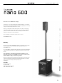 3
3
-
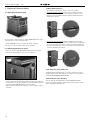 4
4
-
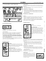 5
5
-
 6
6
-
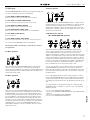 7
7
-
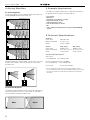 8
8
-
 9
9
-
 10
10
-
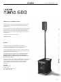 11
11
-
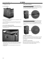 12
12
-
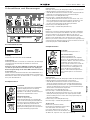 13
13
-
 14
14
-
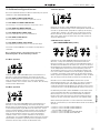 15
15
-
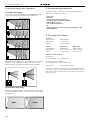 16
16
-
 17
17
-
 18
18
-
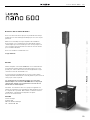 19
19
-
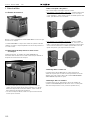 20
20
-
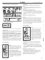 21
21
-
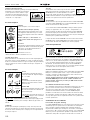 22
22
-
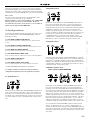 23
23
-
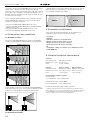 24
24
-
 25
25
-
 26
26
-
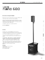 27
27
-
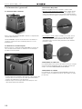 28
28
-
 29
29
-
 30
30
-
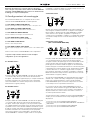 31
31
-
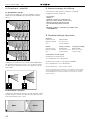 32
32
-
 33
33
-
 34
34
-
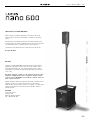 35
35
-
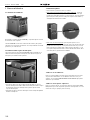 36
36
-
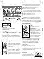 37
37
-
 38
38
-
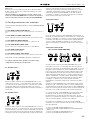 39
39
-
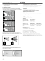 40
40
-
 41
41
-
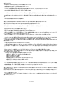 42
42
-
 43
43
-
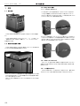 44
44
-
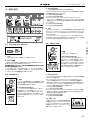 45
45
-
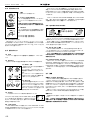 46
46
-
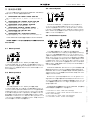 47
47
-
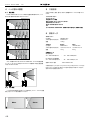 48
48
-
 49
49
-
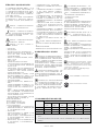 50
50
-
 51
51
-
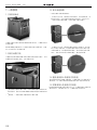 52
52
-
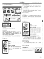 53
53
-
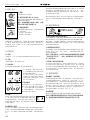 54
54
-
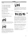 55
55
-
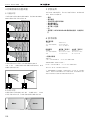 56
56
-
 57
57
-
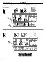 58
58
-
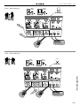 59
59
-
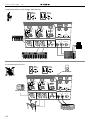 60
60
-
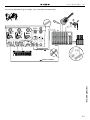 61
61
-
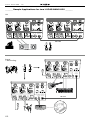 62
62
-
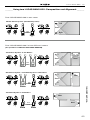 63
63
-
 64
64


HK Audio Lucas nano 600 Manuale utente
- Categoria
- Altoparlanti della soundbar
- Tipo
- Manuale utente
in altre lingue
Documenti correlati
-
HK Audio LUCAS NANO 608i Stereo System Manuale utente
-
HK Audio LUCAS NANO 300 Manuale utente
-
HK Audio Lucas Nano 605 FX Manuale del proprietario
-
-
-
-
-
-
-
HK Audio Lucas 2K18 Manuale utente