SBC High-Current 3-phase energy meter AWD3 Mounting Instructions & Users Guide
- Tipo
- Mounting Instructions & Users Guide

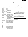
Montage- und Bedienungsanleitung Typ AWD3D5WS
Energiezähler 3-phasig mit Stromwandler mit Serial S-Bus Schnittstelle, Pic. 1
Beschreibung
Energiezähler mit integrierter Serial S-Bus Schnittstelle
ermöglichen das Auslesen aller relevanten Daten wie
Zählerstand, Strom, Spannung und Leistung (aktiv und
reaktiv).
Technische Daten
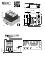
Anschlussbild
■
Pic. 2
Abmessungen
■
Pic. 3
Genauigkeitsklasse
■
B gemäss EN 50470-3,
1 gemäss IEC 62053-21
Referenz-,
■
Iref = 5 A, Imax = 6 A, Ist = 10 mA
Maximal-, Anlaufstrom
Betriebsspannung
■
3 × 230/400 V AC, 50 Hz
Toleranz −20%/+15%
Zählbereich
■
0 000 000…9 999 999 kWh
Anschlüsse
■
Leiterquerschnitt 1,5−16 mm
2
,
Hauptstromkreis Schraubendreher Pozi Nr. 1, Schlitz
Nr. 2, Anzugsmoment 1,5−2 Nm
Anschlüsse
■
Leiterquerschnitt max. 2,5 mm
2
,
LED
■
1 Imp/kWh
Steuerstromkreis Schraubendreher Pozi Nr. 0, Schlitz
Nr. 2, Anzugsmoment 0,8 Nm
Betriebstemperatur
■
−25 … +55 °C (nicht konden-
sierend gemäss Norm EN 50470)
Umgebungs-
■
Mechanische M2
bedingungen Elektromagnetische E2
Anzeigeelemente (Pic. 4)
T1total (
kWh
)
■
Zeigt den Verbrauch Total
T1part.
(
kWh
)
■
Zeigt den partiellen Verbrauch,
dieser Wert ist rückstellbar
CT
■
Zeigt das eingestellte
Stromwandlerverhältnis
Select
■
Bei geöneter Brücke Z1-Z2
kann,
beim Menupunkt Select,
das
Wandlerverhältis eingestellt
werden
P(kW)
■
Zeigt die momentane Leistung
pro Phase oder aller Phasen
zusammen
U(V)
■
Zeigt die Spannung pro Phase
I(A)
■
Zeigt den Strom pro Phase
kWh
■
Zeigt die Einheit kWh bei
Verbrauchsanzeige
L1 / L2 / L3
■
Bei P-, U-, I- oder Error-Anzeige
wird die entsprechende Phase
angezeigt
Error
■
Bei fehlender Phase oder falscher
Stromrichtung. Die entspre-
chende Phase wird zusätzlich
angezeigt.
Hinweise vor dem Anschliessen
1. Nicht die Phase L1, L2 oder L3 an N anschliessen.
2. Um Feuchtigkeit im Zähler durch Kondenswasser zu
vermeiden, den Zähler vor dem Anschliessen ca. eine
halbe Stunde bei Raumtemperatur akklimatisieren.
3. N muss immer angeschlossen sein.
Achtung!
Diese Geräte dürfen nur durch eine Elektrofachkraft
installiert werden, andernfalls besteht Brandgefahr oder
Gefahr eines elektrischen Schlages!
Deutsch
Montagehinweis
Die 3-Phasen-Energiezähler lassen sich auf eine 35 mm
Schiene (EN 60715, TH35) aufschnappen. Sie dürfen nur
in dazu geeigneten Installationsschränken verwendet
werden.
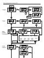
Bedienung der LCD-Anzeige
Siehe Seite mit LCD-Menüführung.
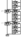
Für das Einstellen des Wandlerverhältnis muss die
Brücke Z1-Z2 entfernt werden.
4 319 5121 0e 06.2015 Änderungen technischer Daten vorbehalten
Anschlussschema
Der sekundär, netzseitige Stromwandleran-
schluss ist mit der zu messenden Phase zu
verbinden und der Stromwandler darf aus
diesem Grund nicht geerdet werden.
Diese Verbindung ist den lokalen Installationsvorschriften
entsprechend abzusichern.

Saia-Burgess Controls AG
Bahnhofstrasse 18 I CH-3280 Murten I Schweiz
T +41 26 580 30 00 I F +41 26 580 34 99
www.sbc-support.com
Deutsch
Technische Daten S-Bus
Bus System S-Bus
Übertragungsraten 4800-9600-19 200-38 400-57 600-115 200.
Die Übertragungsrate wird automatisch erkannt
Übertragungsmodus Data
Bus Länge (max.) 1200 m (ohne Repeater)
Reaktionszeit: Schreiben: 60 ms
Lesen: 60 ms
■ Die Schnittstelle funktioniert nur wenn Phase 1 angeschlossen ist.
■ Die Kommunikation ist 30 s nach Einschalten bereit
■ Energiezähler in einem Bussystem mit hohem Datenaufkommen können zu Leistungseinbusen auf dem Bus führen
■ Die Daten werden alle 10 s aktualisiert, aus diesem Grund sollte der Abfrageintervall eines Energiezählers nicht kürzer
als 10 s sein.
■ 254 Geräte können am S-Bus angeschlossen werden. Bei mehr als 128 Geräten sollte ein Repeater benutzt werden
■ Die Schnittstelle hat keinen Abschlusswiderstand, dieser sollte extern bereitgestellt werden
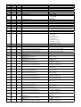
■ Die verwendeten Register sind in der Registerliste beschrieben
Datenübertragung
■
Nur «lese/schreib» Register Befehle werden erkannt.
■
Es kann immer nur ein Register auf einmal beschrieben werden.
■
Das Gerät wird ein „NAK” zurückgeben wenn mehr als ein Register auf einmal beschrieben wird.
■
Es können bis zu 10 Register auf einmal gelesen werden.
■
Das Gerät wird ein “NAK“ zurückgeben wenn mehr als 10 Register auf einmal gelesen werden.
■
Das Gerät wird nicht auf unbekannte Abfragen antworten.
■
Das Gerät hat eine Spannungsüberwachung. Im Falle eines Spannungsabfalls werden die Register im EEPROM gespei-
chert (Übertragungsrate usw.)
Ändern der S-Bus Adresse auf dem Gerät:
■
Um die S-Bus Adresse zu ändern halten Sie 3 s ► gedrückt
■
Im Menü, ▼ erhöht die Adresse um 10, ► erhöht die Adresse um 1
■
Wenn die gewünschte Adresse erreicht ist warten Sie bis die Hauptanzeige wieder erscheint

Assembly and operating instructions AWD3D5WS
Three-phase active power energy meter with serial S-Bus interface, Pic. 1
Description
Energy meter with serial S-Bus interface enables the reading
of all relevant data like consumption, current, voltage and
power (active and reactive).
Indicating elements
(Pic. 4)
T1total (
kWh
)
■
Shows total consumption
T1part. (
kWh
)
■
Shows partial consumption, this
value is resettable
CT
■
Shows the set current transformer
ratio
Select
■
When the Z1-Z2 bridge is open the
transformer ratio can be selected
under Menu item Select.
P(kW)
■
Shows the instantaneous power
per phase or all phases
U(V)
■
Shows the voltage per phase
I(A)
■
Shows the current per phase
kWh
■
Shows the unit kWh when the
consumption is displayed
L1 / L2 / L3
■
For P-, U-, I- or Error display, the
corresponding phase is displayed
Error
■
In case of missing phase or wrong
current direction. The correspond-
ing phase is additionally displayed.
Technical data
Connection
■
Pic. 2
diagram
Dimensions
■
Pic. 3
Accuracy class
■
B according to EN 50470-3,
1 according to IEC 62053-21
Reference, Maxi-
■
Iref = 5 A, Imax = 6 A, Ist = 10 mA
mum, initial current
operating voltage
■
3 × 230/400 V AC, 50 Hz
Tolerance −20%/+15%
Counting range
■
0 000 000…9 999 999 kWh
Connections
■
Conductor cross-section 1,5−16 mm
2
,
Main circuit screwdriver pozi no. 1, slot n
o. 2,
torque 1,5−2 Nm
Connections
■
Conductor cross-section max. 2,5 mm
2
,
LED
■
1 Imp/kWh
Control circuit screwdriver pozi no. 0, slot no. 2,
torque 0,8 Nm
Operating
■ −
25 … +55 °C (noncondensing
temperature according standard EN 50470)
Environment
■
Mechanical M2
Electromagnetic E2
Notes before connecting
1. Do not connect L1, L2 or L3 to N
2. In order to avoid moisture in the meter due to condensa-
te build-up, acclimatise the meter at room temperature
for about half an hour before connecting.
3. N must always be connected.
Attention!
These devices must only be installed by a professional
electrician, otherwise there is the risk of re or the risk of
an electric shock.
English
Installation instructions
The three-phase energy meter can be attached to a 35 mm
rail (EN 60715, TH35).
The meter can be used only in installation cabinets.
Operation of the LCD display
See page with LCD menu navigation.
The bridge Z1-Z2 should be removed for adjusting the
transformer ratio.
4 319 5121 0e 06.2015 Subject to change without notice
Wiring diagram
The secondary, mains current transformer
connection is to be connected to the phase to
be measured and therefore the transformer
don’t have to be grounded.
This connection is to be fused according to the local
installation instructions.

Saia-Burgess Controls AG
Bahnhofstrasse 18 I CH-3280 Murten I Schweiz
T +41 26 580 30 00 I F +41 26 580 34 99
www.sbc-support.com
Technical data S-Bus
Bus system S-Bus
Transmission rate 4800-9600-19 200-38 400-57 600-115 200.
The transmission Baud rate is automatically detected
Transmission mode Data
Bus length (max.) 1200 m (without repeater)
Response time: Write: 60 ms
Read: 60 ms
■
The interface works only if the phase 1 is connected.
■
The communication is ready 30 s after the power on.
■
The use of energy meter in Bus with intensive communication could reduce the performance of the Bus
■
Refresh time for the data is 10 s. For this reason one energy meter should be not polled faster as 10 s.
■
254 devices could be connected to the S-Bus. Over 128 devices, a repeater should be used.
■
The interface don’t have a terminal resistor, this should be provided external.
■
For a description of the used registers please look at the register page
Data transmission
■
Only «read/write» register instructions are recognized.
■
Only one register can be written at a time.
■
The device will respond „NAK“ if more than 1 register is written.
■
Up to 10 Registers could be read at a time.
■
The device will respond „NAK“ if more than 10 registers are read.
■
The device will not respond to any unknown query.
■
The device has a voltage monitoring system. In case of voltage loss, registers are stored in EEPROM
(transmission rate» etc.)
Change the S-Bus address direct on device
■
To modify the S-Bus address, press 3 sec on ► touch
■
In menu, ▼ increase address by 10, ► increase by 1
■
Once the address is selected wait for the root menu to come back
English

Italiano
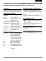
Istruzioni d’uso e montaggio Modello AWD3D5WS
Contatore d’energia attiva trifase con interfaccia seriale S-Bus, Pic. 1
Descrizione
Il contatore d’energia con interfaccia seriale integrata
consiente la lettura tutti i dati rilevanti, quali registro del
contatore, corrente, tensione e potenza (attiva e reattiva).
Dati tecnici
Schema di
■
Pic. 2
collegamento
Dimensioni
■
Pic. 3
d’ingombro
Classe di
■
B secondo EN 50470-3,
precisione 1 secondo IEC 62053-21
Corrente di riferi-
■
Iref = 5 A, Imax = 6 A, Ist = 10 mA
mento, massima, di spunto
Tensione
■
3 × 230/400 V AC, 50 Hz
d’esercizio Tolleranza −20%/+15%
Capacità di
■
0 000 000…9 999 999 kWh
conteggio
LED
■
1 Imp/kWh
Morsetti
■
Sezione conduttori 1,5−16 mm
2
,
circuito principale
cacciavite pozi nr. 1, a taglio nr. 2,
coppia di serraggio 1,5−2 Nm
Morsetti
■
Sezione conduttori max. 2,5 mm
2
,
circuito di comando
cacciavite pozi nr. 0, a taglio nr. 2,
coppia di serraggio 0,8 Nm
Temperatura
■
−25 … +55 °C (assenza di con--
d’esercizio
densa secondo la norma EN 50470)
Ambienti
■
meccanici M2
elettromagnetici E2
Elementi a display
(Pic. 4)
T1total (
kWh
)
■
indica il consumo totale
T1part. (
kWh
)
■ indica il consumo parziale, questo
valore è azzerabile
CT
■ indica il rapporto di trasformazio-
ne di corrente
Select
■
a ponte Z1-Z2 aperto è possibile
di regolare il rapporto di trasfor-
mazione di corrente nel menu
select
P(kW)
■
indica la potenza istantanea per
ciascuna fase o per tutte le fasi
U(V)
■
indica la tensione per ciascuna fase
I(A)
■
indica la corrente per ciascuna fase
kWh
■
indica il consumo rilevato in kWh
L1 / L2 / L3
■
è la fase interessata per P,U,I
o Errore
Error
■
In caso di mancanza di una fase
o di direzione della corrente
sbagliata. Viene visualizzata la fase
interessata
Note per il collegamento
1. Non collegare la fase L1, L2 o L3 a N.
2. Per evitare la presenza di umidità nel contatore in
seguito alla formazione di acqua di condensa, prima del
collegamento lasciare il contatore per circa mezz’ora a
temperatura ambiente
3. N deve sempre essere collegato.
Attenzione!
Questi apparecchi devono essere installati esclusivamente
da elettricisti specializzati, onde evitare rischi di incendio o
pericoli di scosse elettriche!
Istruzioni di montaggio
I contatori di energia trifase si installano su guida da
35 mm (EN 60715, TH35). Devono essere installati solo in
quadri o centralini
Funzione del display LCD
Per ulteriori dettagli vedi pagina LCD con menù guidato.
Per la regolazione del rapporto di trasformazione di
corrente occorre rimuovere il ponte Z1-Z2
4 319 5121 0e 06.2015 Soggetto a modiche senza preavviso
Schema di collegamento
Il collegamento secondario del trasformatore
amperometrico, sul lato alimentazione, va
collegato alla fase da misurare e quindi il tras-
formatore non deve essere messo a terra.
Questo collegamento va messo in sicurezza seguendo le
norme di installazione locali.

Saia-Burgess Controls AG
Bahnhofstrasse 18 I CH-3280 Murten I Schweiz
T +41 26 580 30 00 I F +41 26 580 34 99
www.sbc-support.com
Italiano
Dati tecnici S-Bus
Sistema Bus S-Bus
Velocità di trasmissione 4800-9600-19 200-38 400-57 600-115 200.
La velocità di trasmissione viene riconosciuta automaticamente
Modalità di trasmissione Dati
Lunghezza Bus (max.) 1200 m (senza ripetitore)
Tempo di risposta Scrittura: 60 ms
Lettura: 60 ms
■ L’interfaccia funziona solo con fase 1 collegata.
■ La comunicazione è operativa 30 s dopo l’accensione
■ L’inserimento del contatore d’energia in un sistema bus con intènsiva communicazione di dati può diminuire le presta-
zioni del bus
■ L’aggiornamento dei dati avviene ogni 10 s, di conseguenza, l’intervallo d’interrogazione del contatore non dovrebbe
essere inferiore a 10 s.
■ È possibile collegare fino a 254 dispositivi al S-Bus. In caso di più di 128 dispositivi si consiglia l’utilizzo di un ripetitore.
■ L’interfaccia non è provvista di resistenza terminale che quindi dovrà essere messa a disposizione separatamente.
■ I registri utilizzati sono descritti nell’elenco dei registri
Trasmissione dei dati
■ Il sistema riconosce solo comandi di registro del tipo «leggi/scrivi».
■ È possibile scrivere solo un in registro alla volta.
■ Il dispositivo restituirà il messaggio “NAK” in caso di scrittura contemporanea di più di un registro.
■ È possibile leggere fino a 10 registri contemporaneamente.
■ Il dispositivo restituirà il messaggio “NAK” in caso di lettura contemporanea di più di 10 registri.
■ Il dispositivo non risponderà ad interrogazioni sconosciute.
■ Il dispositivo è provvisto di un sistema di controllo della tensione. In caso di caduta di tensione, il sistema memorizzerà
i registri nella EEPROM (velocità di trasmissione, ecc.)
Modica dell’indirizzo S-Bus nel dispositivo
■ Per modificare l’indirizzo S-Bus tenere premuto il tasto
► per 3 s
■ Dal menù, premere
▼ per aumentare l’indirizzo di 10, premere ► per aumentare l’indirizzo di 1
■ Una volta raggiunto l’indirizzo desiderato, aspettare ché il sistema ritorni alla visualizzazione principale

Francais
4 319 5121 0e 06.2015 Sous réserve de modications sans préavis
Instructions de montage et d’exploitation AWD3D5WS
Compteur d’énergie active triphasé avec interface Serial S-Bus, Pic.1
Description
Les compteurs d’énergie avec interface Serial S-Bus
permettent le relevé de toutes les données importantes
telles que l'énergie, le courant, la tension et la puissance
(active et réactive).
Caractéristiques techniques
Schéma de
■
Pic. 2
raccordement
Dimensions
■
Pic. 3
Classe de
■
B selon EN 50470-3,
précision 1 selon IEC 62053-21
Courant de
■
Iref = 5 A, Imax = 6 A, Ist = 10 mA
référence, maximal, de démarrage
Tension de service
■
3 × 230/400 V AC, 50 Hz
Tolérance −20%/+15%
Plage de comptage
■
0 000 000…9 999 999 kWh
LED
■
1 Imp/kWh
Branchements
■
Section de conducteur
1,5−16 mm
2
,
Circuit d’alimentation tournevis pozi n° 1, plat n
° 2,
couple de serrage 1,5−2 Nm
Branchements
■
Section de conducteur max. 2,5 mm
2
,
Circuit de commande tournevis pozi n° 0, plat n° 2,
couple de serrage 0,8 Nm
Température de
■
−25°…+55 °C (sans condensation
service selon la norme EN 50470)
Environnement
■
mécanique M2
electromagnétiques E2
Eléments d’achage
(Pic. 4)
T1total (kWh)
■
Indique la consommation totale
T1part. (kWh)
■
Indique la consommation partielle,
cette valeur est réinitialisable
CT
■
Indique le rapport de trans-
formation de courant défini
Select
■
Lors que le pontage Z1-Z2 est ou-
vert, le rapport de transformation
peut être réglé sous l‘option de
menu Select
P(kW)
■
Indique la puissance instantanée
par phase ou de toutes les phases
U(V)
■
Indique la tension par phase
I(A)
■
Indique le courant par phase
kWh
■
Indique l’unité kWh pour
l’affichage de consommation
L1 / L2 / L3
■
En cas d’affichage P, U, I ou Error, la
phase correspondante s’affiche
Error
■
En cas d’absence de phase ou
de sens de courant inversé. La
phase correspondante s’affiche
également.
Remarque préalable au raccordement
1. Ne pas raccorder la phase L1, L2 ou L3 à N.
2. An d’éviter la formation de condensation dans le
compteur, laisser celui-ci s’acclimater pendant env. une
demi heure à la température ambiante du local.
3. N doit toujours être connecté.
Attention!
Ces appareils doivent être uniquement installés par un
spécialiste en électricité pour éviter tout risque d’incendie
ou d’électrocution !
Instructions de montage
Les compteurs d’énergie Triphasé peuvent être encliquetés
sur un rail de 35 mm (EN 60715, TH35). Ils ne peuvent être
utilisés que dans des armoires électriques.
Utilisation de l’écran LCD
Voir la page avec le guidage de menu LCD.
Le pontage Z1-Z2 doit être retiré pour régler le rapport de
transformation.
Schéma des connexions
Le branchement secondaire côté secteur du
transformateur d’intensité doit être relié à la
phase à mesurer et le transformateur d’intensité
ne doit pas être mis à la terre
dans ce cas.
Ce branchement doit être protégé conformément aux
réglementations d’installation locales.

Saia-Burgess Controls AG
Bahnhofstrasse 18 I CH-3280 Murten I Schweiz
T +41 26 580 30 00 I F +41 26 580 34 99
www.sbc-support.com
Francais
Caractéristiques techniques du S-Bus
Système de bus S-Bus
Vitesse de communication 4800-9600-19 200-38 400-57 600-115 200.
La vitesse de communication est déterminée automatiquement
Mode de transmission Données
Longueur du bus (max.) 1200 m (sans répéteur)
Temps de réaction: Ecriture: 60 ms
Lecture: 60 ms
■ L’interface ne fonctionne que si la phase 1 est alimentée.
■ La communication est opérationnelle 30 secondes après l’enclenchement du compteur.
■ Les compteurs d’énergie dans un système de bus véhiculant d’importantes quantités de données peuvent entraîner
des pertes de puissance du bus.
■ Les données sont actualisées toutes les 10 secondes. L’intervalle entre chaque requête sur un compteur d’énergie ne
devrait pas être inférieur à 10 secondes.
■ 254 appareils peuvent être connectés au S-Bus. Lorsque le nombre d’appareils est supérieur à 128, utiliser si possible
un répéteur.
■ L’interface n’est pas dotée d’une résistance de terminaison, celle-ci doit être mise en place de façon externe.
■ Les registres utilisés sont décrits dans la liste de registres.
Transfert de données
■ Seules les instructions de registre « lecture/écriture » sont détectées.
■ L’écriture ne peut toujours avoir lieu qu’en un seul registre à la fois.
■ L’appareil renverra un signal « NAK » si l’écriture concerne plus d’un registre en même temps.
■ Jusqu’à 10 registres peuvent être lus en même temps.
■ L’appareil renverra un signal « NAK » si la lecture concerne plus de 10 registres en même temps.
■ L’appareil ne répond pas aux interrogations inconnues.
■ L’appareil est doté d’une surveillance de la tension. En cas de chute de tension, les registres sont enregistrés dans
l’EEPROM (taux de transfert, etc.).
Modication de l’adresse de S-bus sur l’appareil
■ Pour modifier l’adresse du S-bus, maintenir la touche
► appuyée pendant 3 secondes.
■ Dans le menu, la touche
▼ incrémente l’adresse de 10 et la touche ► l‘incrémente de 1.
■ Lorsque l’adresse souhaitée est atteinte, attendre que le menu principal s’affiche de nouveau.

82
27
62
4,5
6
70
6
5 x 11,7 = (58,5)
7
68
4,5
9
30,5
9
11
57,7
22,7
35
69,5
31
62
70
9
57.7
30.5
22.7
4.5
11
35
5 x 11.7 = [58.5]
6
4.5
27
31
45
82
69.5
768
6
9
Pic. 1
Pic. 3
Pic. 2
Pic. 4
CT
Select
D /D
L1
L2
L3
N
Fuse: T 250 mA (3×)
4 319 5121 0e
Fuse: min. T 250 mA (3x)
3× 230 VAC/400VAC

R Read Write Description Value / Unit
0
X
Firmware-Version Ex: „11“= FW 1.1
1
X
Number of supported registers will give „41“
2
X
Number of supported ags will give „0“
3
X
Baudrate BPS
4
NOT USED will give a „0“
5
X
ASN (letter 1-4) will give „AWD3“
6
X
ASN (letter 5-8) will give “D5WS”
7
X
ASN (letter 9-12) will give “00Dx”
x : 2 = Non MID
x : 3 = MID
8
X
ASN (letter 13-15) will give “A00”
9
X
HW Vers. Modif Ex: „11“= FW 1.1
10
NOT USED will give a „0“
11
Serialnumber Serialnumber high
12
X
Serialnumber Serialnumber low
13 NOT USED will give a „0“
14
X
Status „0“ = no Problem
„1“ = Problem with last communication request
15
X
S-Bus Timeout ms
16
X X
S-Bus Address
17
X
Error Flags 0 : No error
1 : Error Phase 1
2 : Error Phase 2
3 : Error Phase 1 and 2
4 : Error Phase 3
5 : Error Phase 1and 3
6 : Error Phase 2 and 3
7 : Error Phase 1, 2 and 3
18
X
Current transformer ratio Ex: Transformer 1000/5 give „200“
19
X
NOT USED will give a „0“
20
X
WT1 total Counter Energy Total Tarif 1
10
-1
kWh.
Ex: 0912350 = 091235,0 kWh
21
X X
WT1partial Counter Energy partial Tarif 1
Any written value reset the counter
10
-1
kWh.
Ex: 0912350 = 091235,0 kWh
22
X
NOT USED will give a „0“
23
X
NOT USED will give a „0“
24
X
URMS phase 1
Eective Voltage of Phase 1
V
Ex: 230 = 230 V
25
X
IRMS phase 1
Eective Current of phase 1
A
Ex: 145 = 145 A
26
X
PRMS phase 1
Eective active Power of phase 1
10
-1
kW
Ex: 15450 = 1545,0 kW
27
X
QRMS phase 1
Eective reactive power of phase 1
10
-1
kVAr
Ex: 15450 = 1545,0 kVAr
28
X
cos phi phase 1 10
-2
(multiplier 0.01)
Ex: 67 = 0.67
29
X
URMS phase 2
Eective Voltage of Phase 2
V
Ex: 230 = 230 V
30
X
IRMS phase 2
Eective Current of phase 2
A
Ex: 145 = 145 A
31
X
PRMS phase 2
Eective active Power of phase 2
10
-1
kW
Ex: 15450 = 1545,0 kW
32
X
QRMS phase 2
Eective reactive power of phase 2
10
-1
kVAr
Ex: 15450 = 1545,0 kVAr
33
X
cos phi phase 2 10
-2
(multiplier 0.01)
Ex: 67 = 0.67
34
X
URMS phase 3
Eective Voltage of Phase 3
V
Ex: 230 = 230 V
35
X
IRMS phase 3
Eective Current of phase 3
A
Ex: 145 = 145 A
36
X
PRMS phase 3
Eective active Power of phase 2
10
-1
kW
Ex: 15450 = 1545,0 kW
37
X
QRMS phase 3
Eective reactive power of phase 3
10
-1
kVAr
Ex: 15450 = 1545,0 kVAr
38
X
cos phi phase 3 10
-2
(multiplier 0.01)
Ex: 67 = 0.67
39
X
PRMS total
Eective active Power of all phase
10
-1
kW
Ex: 15450 = 1545,0 kW
40
X
QRMS total
Eective reactive power of all phase
10
-1
kVAr
Ex: 15450 = 1545,0 kVAr

Menu to display the value on LCD
I(A)
U(V)
Error
T1
part.
T2
total
T2
part.
T1
total
P
(kW)
L1
L3
L2
I(A)
U(V)
Error
T1
part.
T2
total
T2
part.
T1
total
P
(kW)
L1
L3
L2
I(A)
U(V)
Error
T1
part.
T2
total
T2
part.
T1
total
P
(kW)
L1
L3
L2
I(A)
U(V)
Error
T1
part.
T2
total
T2
part.
T1
total
P
(kW)
L1
L3
L2
Start
I(A)
U(V)
Error
T1
part.
T2
total
T2
part.
T1
total
P
(kW)
L1
L3
L2
I(A)
U(V)
Error
T1
part.
T2
total
T2
part.
T1
total
P
(kW)
L1
L3
L2
I(A)
U(V)
Error
T1
part.
T2
total
T2
part.
T1
total
P
(kW)
L1
L3
L2
T1 total
T1 part
Ratio
Current
Transformer (CT)
Instan.
Power P
> 3 s
>
3 s
I(A)
U(V)
Error
T1
part.
T2
total
T2
part.
T1
total
P
(kW)
L1
L3
L2
I(A)
U(V)
Error
T1
part.
T2
total
T2
part.
T1
total
P
(kW)
L1
L3
L2
I(A)
U(V)
Error
T1
part.
T2
total
T2
part.
T1
total
P
(kW)
L1
L3
L2
AWD3D5WS00D_A00 1000 … 6000 A
1000:5 1200:5 1500:5 2000:5 2500:5
3000:5 4000:5 5000:5 6000:5
remove
bridge Z1-Z2
restore
bridge Z1-Z2
I(A)
U(V)
Error
T1
part.
T2
total
T2
part.
T1
total
P
(kW)
L1
L3
L2
I(A)
U(V)
Error
T1
part.
T2
total
T2
part.
T1
total
P
(kW)
L1
L3
L2
I(A)
U(V)
Error
T1
part.
T2
total
T2
part.
T1
total
P
(kW)
L1
L3
L2
> 3 s
Start
> 20 s

I(A)
U(V)
Error
T1
part.
T2
total
T2
part.
T1
total
P
(kW)
L1
L3
L2
I(A)
U(V)
Error
T1
part.
T2
total
T2
part.
T1
total
P
(kW)
L1
L3
L2
I(A)
U(V)
Error
T1
part.
T2
total
T2
part.
T1
total
P
(kW)
L1
L3
L2
I(A)
U(V)
Error
T1
part.
T2
total
T2
part.
T1
total
P
(kW)
L1
L3
L2
I(A)
U(V)
Error
T1
part.
T2
total
T2
part.
T1
total
P
(kW)
L1
L3
L2
I(A)
U(V)
Error
T1
part.
T2
total
T2
part.
T1
total
P
(kW)
L1
L3
L2
Voltage
U
Current
I
Start
I(A)
U(V)
Error
T1
part.
T2
total
T2
part.
T1
total
P
(kW)
L1
L3
L2
I(A)
U(V)
Error
T1
part.
T2
total
T2
part.
T1
total
P
(kW)
L1
L3
L2
I(A)
U(V)
Error
T1
part.
T2
total
T2
part.
T1
total
P
(kW)
L1
L3
L2
I(A)
U(V)
Error
T1
part.
T2
total
T2
part.
T1
total
P
(kW)
L1
L3
L2
-
 1
1
-
 2
2
-
 3
3
-
 4
4
-
 5
5
-
 6
6
-
 7
7
-
 8
8
-
 9
9
-
 10
10
-
 11
11
-
 12
12


SBC High-Current 3-phase energy meter AWD3 Mounting Instructions & Users Guide
- Tipo
- Mounting Instructions & Users Guide
in altre lingue
Documenti correlati
-
SBC 3-phase energy meter AWD3 Mounting Instructions & Users Guide
-
SBC 3-phase energy meter AWD3 KV44 Mounting Instructions & Users Guide
-
-
-
-
-
-
-
-