
TP7000 Range
Electronic 7 Day Programmable
Room Thermostat
Installation Guide
Danfoss Heating
MAKING MODERN LIVING POSSIBLE

TP7000 RANGE
2
For a large print version of these instructions
please call Marketing on 0845 121 7400.
Danfoss can accept no responsibility for possible errors in catalogues, brochures, and other
printed material. All trademarks in this material are property of the respective companies.
Danfoss and the Danfoss logotype are trademarks of Danfoss A/S. All rights reserved.
®
Certification Mark

Danfoss Heating
3
F
D
ES
DK
NL
I
GR
PL
LT
CZ
HR
RO
GB
Installation Instructions
TP7000 Range
Electronic Programmable Room Thermostat
Index
1.0 Installation Guide .....................................................................................4
2.0 System Overview ....................................................................................... 4
3.0 Installation ...................................................................................................5
3.1 DIL Switch Settings ...........................................................................5
3.2 Setting Optimum Start Control ....................................................6
3.3 TP7000 Wiring (Not RF models) ....................................................6
3.4 Receiver Wiring (RF models) ..........................................................7
3.5 Commissioning (RF versions only)...............................................7

TP7000 RANGE
4
F
D
ES
DK
NL
I
GR
PL
LT
CZ
HR
RO
GB
Thermostat Features TP7000-RF
TP7000
TP7000A
TP7000-M
TP7000-MA
TP7000-M 24
Power supply
2 x AA/MN1500/LR6
alkaline batteries
230v, 50 Hz 24v, 50 Hz
Memory backup
Capacitor during
battery change for 1
minute
Rechargable cell, 24 hrs (*1)
Switching action of output
relay
N/A 1 x SPDT, Type 1B
Switch rating of relay contact,
voltage and current
N/A 3(1) A, 10-230 volts
Transmitter frequency
(RF only)
433.92 MHz N/A
Transmitter range
(RF only)
30m max. N/A
Rated Impulse Voltage N/A 2.5Kv
Dimensions (mm) 138 wide x 88 high x 28 deep
Ball Pressure Test 75°C
Temperature Range 5-30°C
Design Standard EN 60730-2-7 (EN300220 for RF)
Control Pollution Situation Degree 2
Time accuracy ± 1 min.
Temperature accuracy ±1°C
*1: Unit must powered up for 6 days to charge cell before full back-up is available
Important note RF products: Ensure that there are no large metal
objects, such as boiler cases or other large appliances, in line of
sight between the transmitter and receiver as these will prevent
communication between thermostat and receiver.
1.0 Installation Guide
2.0 System Overview
Please Note:
This product should only be installed by a qualifi ed electrician or
competent heating installer and should be in accordance with the
current edition of the IEEE wiring regulations.

Danfoss Heating
5
F
D
ES
DK
NL
I
GR
PL
LT
CZ
HR
RO
GB
All models
w
1
5/2 day programming 7 day programming
w
2
Optimum start contoller enabled Optimum start contoller disabled
w
3
Chrono-proportional control On/O control
TP7000, M, & RF models with 3/6 cycles per hour option
w
4
Chrono-proportional, 6 cycles / hour Chrono-proportional, 3 cycles / hour
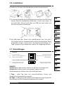
3.1 DIL Switch Settings
First remove the wallplate from the back of the unit.
From the top left hand corner of the wallplate, there must be
clearances of at least 15mm to the right, 15mm to the left, 30mm
above and 100mm below in order to mount the plug-in module.
Before mounting the unit ensure the 4 DIL switches on the
rear of the unit have been moved to the required settings (see
below). Factory preset is 7-day, with Optimum Start and Chrono-
proportional control OFF.
NOTE
Use Chrono 3 for high thermal inertia systems, e.g. fl oor standing cast iron
boilers.
Use Chrono 6 for low thermal inertia systems, e.g. low water content
boilers and combi boilers.
3.0 Installation

TP7000 RANGE
6
F
D
ES
DK
NL
I
GR
PL
LT
CZ
HR
RO
GB
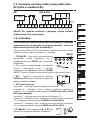
3.3 TP7000 Wiring (not RF models)
7-day - each day can be programmed with diff erent times and
temperatures.
5/2 day - one set of times & temperatures for weekdays, and another
set for weekends.
Optimum start control - function which switches the heating on
earlier than the Event 1 programmed time to ensure the required
temperature is achieved by the set time.
Chrono-proportional control - energy saving feature which fi res the
boiler at regular intervals to maintain a set temperature, achieving a
constant ambient environment for the user.
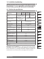
3.2 Setting Optimum Start Control
-4°C
-3°C
-2°C
-1°C
A
B
C
120
min.
90
min.
60
min.
30
min.
Event 1
time (0
)
D
Set Sw2 to OSC ON
(see DIL settings page 4)
Select OPTIMISER CURVE in
programming mode
A Event 1 Set Point
B Deviation from Set Point
C Switch On Time prior to Event
D Optimiser Curve Setting
1
234567
ELECTRONICS
REMOTE
SENSOR
'A' models
only
COM
ON
OFF
B
C
M 24V models only
24V
L
N
M 230V models only
230V
Note: 1.0mm
2
solid copper cable should be used to connect the
remote sensor to the TP7000A. Please ensure that:
a) the cable length does not exceed 50 metres,
b) to avoid electrical interference the cable should not be run
parallel in close proximity to other cables carrying mains electricity,
and where necessary the cable should cross over mains cabling at
right angles.

Danfoss Heating
7
F
D
ES
DK
NL
I
GR
PL
LT
CZ
HR
RO
GB
1. TP7000-RF
Press the recessed RESET button, using a non-
metallic object, to reset the unit.
2. Press & hold the recessed LEARN button for 3
seconds, using a non-metallic object.
NOTE: Thermostat now transmits continuously for 5 mins.
3. RX1 - Press and hold buttons PROG and CH1
for 3 seconds until green light fl ashes once.
4. RX2 (if applicable)
Stat 1 - perform steps 1-3.
Stat 2 - wait 5 mins, perform steps1-2 and then press PROG and CH2
on RX2.
RX3 (if applicable)
Stat 1 - perform steps 1 – 3.
Stat 2 - wait 5 mins, perform steps 1-2 and then press PROG and CH2
on RX3.
Stat 3 - wait 5 mins, perform steps 1-2 and then press PROG and CH3
on RX3.
5. TP7000-RF - Press or to return the unit
to normal operation.
3.5 Commissioning (RF versions only)
If the thermostat and the receiver have been supplied together
in a combined pack, the units have been paired in the factory
and no commissioning is required (RX1 only).
To tune the RX receiver to the frequency of the thermostat signal, follow
steps 1-5 below.
RX1
LEARN
RESET
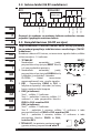
3.4 Receiver Wiring (RF models only)
12
3
4
ELECTRONICS
N
L
COM
ZONE
1 ON
ZONE
1 OFF
A
ELECTRONICS
B
C1
2
345
6
N
L
ZONE
1 ON
ZONE
1 OFF
ZONE
2 ON
ZONE
3 ON
COM
TERMINAL 6
RX3 ONLY
RX1 RX2 & RX3
Note: 1) For mains voltage operated systems link terminal 2 to mains live supply.
2) Power supply to unit must not be switched by timeswitch.

TP7000 RANGE
8
GB
D
ES
DK
NL
I
GR
PL
LT
CZ
HR
RO
F
Instructions d’installation
Série TP7000
Thermostats d’ambiance programmable
Index
1.0 Instructions d’installation ..................................................................... 9
2.0 Specifi cations .............................................................................................. 9
3.0 Installation ................................................................................................ 10
3.1 Réglages d’installateur .................................................................. 10
3.2 Démarrage anticipé (OSC) ........................................................... 11
3.3 TP7000 Câblage (versions câblées seulement) .................... 11
3.4 Câblage du Récepteur RX (modèles RF uniquement) ....... 12
3.5 Instructions (versions câblées) ................................................... 12

Danfoss Heating
9
GB
D
ES
DK
NL
I
GR
PL
LT
CZ
HR
RO
F
1.0 Instructions d’installation
Importante: Veiller à ce qu’aucun gros objet métallique (caisson de
chaudière ou autres gros appareils domestiques) ne fasse obstacle aux
communications entre le thermostat et le récepteur.
2.0 Specifi cations
Caractéristiques TP7000-RF
TP7000
TP7000A
TP7000M
TP7000MA
TP7000M 24
Alimentation
2 piles alcalines AA/
MN 1500/LR6
230v, 50 Hz 24v, 50 Hz
Mémoire non volatile
Suffi sante pour
remplacer les piles
endéans la minute
Rechargeable
(voir note 1*)
Type de contact N/A 1 x SPDT, Type 1B
Charge de contact,
voltage et courant
N/A 3(1) A, 10-230V
Fréquence d’émission
(modèles RF)
433.92 MHz N/A
Rayon d’action
(modèle RF uniquement)
Max. 30
métres
N/A
Tension assignée de
tenue au choc
N/A 2.5Kv
Dimensions (mm) 138 largeur x 88 hauteur x 28 profondeur
Essai à la bille 75°C
Plage de températures 5-30°C
Normes de fabrication EN 60730-2-7 (EN300220 pour RF)
Pollution Degré 2
Précision de l’horloge ± 1 min.
Précision de la
température
±1°C
Note 1) : Le thermostat doit être alimenté pendant 6 jours pour disposer de la
mémoire non volatile.
Remarque:
Ce produit doit être installé exclusivement par un électricien
qualifi é ou un installateur de chauff age compétent et doit être
conforme à la version en vigueur des réglementations de câblage
IEEE.

TP7000 RANGE
10
GB
D
ES
DK
NL
I
GR
PL
LT
CZ
HR
RO
F
3.0 Installation
Retirez tout d’abord la plaque murale de l’arrière de l’appareil.
Par rapport au coin gauche supérieur de la plaque murale, vous
devez disposer d’espacements d’au moins 15 mm à droite, 15
mm à gauche, 30 mm au-dessus et 100 mm en-dessous afi n de
pouvoir monter le module enfi chable.
Avant de monter l’appareil, assurez-vous que les 4 microcontacts
situés à l’arrière de l’appareil soient placés dans les positions
requises (voir ci-dessous). Le pré-réglage d’usine est 7 jours,
avec la régulation Optimum Start (démarrage optimum) et sans
démarrage anticipé (OSC OFF) et en mode Tout ou Rien.
3.1 Réglages d’installateur
REMARQUE
Utilisez Chrono 3 pour les systèmes à inertie thermique élevée, ex.
chaudières en fonte au sol.
Utilisez Chrono 6 pour les systèmes à faible inertie thermique, ex.
chaudières à faible contenu d’eau et chaudières mixtes.
Tous les modèles
Sw
1
Programmation 5/2 jours Programmation 7 jours
Sw
2
Optimum Start Contol on Optimum Start Contol off
Sw
3
Règulation Chrono-proportionnelle Règulation On/Off
TP7000, M, & RF modèles avec 3 ou 6 cycles par heure
Sw
4
Chrono-proportionnelle, 6 cycles par heure Chrono-proportionnelle, 3 cycles par heure

Danfoss Heating
11
GB
D
ES
DK
NL
I
GR
PL
LT
CZ
HR
RO
F
1
234567
ELECTRONICS
REMOTE
SENSOR
'A' models
only
COM
ON
OFF
3.3 TP7000 Câblage (versions câblées seulement)
7 jours – chaque jour peut être programmé avec des heures et des
températures diff érentes.
5/2 jours – une série d’heures et de températures pour les jours de la
semaine, et une autre série pour le week-end.
Régulation démarrage optimum - fonction qui allume le chauff age
avant l’heure programmée de la Période 1 pour s’assurer que la
température désirée soit atteinte à l’heure défi nie.
Chrono-proportionnel – fonction d’économie d’énergie qui
déclenche la chaudière à intervalles réguliers pour maintenir une
température défi nie, off rant un environnement ambiant constant à
l’utilisateur.
3.2 Démarrage anticipé (OSC)
-4°C
-3°C
-2°C
-1°C
A
B
C
120
min.
90
min.
60
min.
30
min.
Ordre N° 1
time (0)
D
Mettez Sw² en position OSC On
(pg.14)
Réglez la courbe optimale en
mode programmation
A - Température choisie ordre n°1
B - Déviation température choisie
C - Temps d’anticipation de
démarrage pour ordre n° 1
D - Courbes optimales disponibles
B
C
M 24V models only
24V
L
N
M 230V models only
230V
Nota: un câble de cuivre de 1 mm2 peut être utilisé pour raccorder la
sonde à distance au TP7000A. S’assurer que :
a) la longueur de câble ne dépasse pas 50 mètres
b) le câble ne chemine pas le long d’un autre câble véhiculant du 230
V ou plus , et si besoin faire des croisements de câbles angle droit.

TP7000 RANGE
12
GB
D
ES
DK
NL
I
GR
PL
LT
CZ
HR
RO
F
1. TP7000-RF
Appuyez sur la touche RESET encastrée,
à l’aide d’un objet non-métallique, pour
réinitialiser l’appareil.
2. Appuyez sur la touche LEARN encastrée en la maintenant enfoncée
pendant 3 secondes, à l’aide d’un objet non-métallique. (Le TP7000
transmet alors un signal unique en continu pendant 5 minutes).
3. RX1 - Appuyez sur les touches PROG et
CH1 en les maintenant enfoncées pendant 3
secondes jusqu’à ce que le voyant vert clignote
une fois.
4. RX2 (si applicable)
Etat 1 – exécutez les points 1-3.
Etat 2 - patientez 5 min, exécutez les points 1-2 puis appuyez sur les
touches PROG et CH2 du RX2.
RX3 (si applicable)
Etat 1 – exécutez les points 1-3.
Etat 2 - patientez 5 min, exécutez les points 1-2 puis appuyez sur les
touches PROG et CH2 du RX3.
Etat 3 - patientez 5 min, exécutez les points 1-2 puis appuyez sur les
touches PROG et CH3 du RX3.
5. TP7000-RF - Appuyez sur ou pour
sélectionner la température – l’appareil
repassera en mode de fonctionnement.
RX1
3.5 Instructions (versions câblées)
Si le thermostat émetteur et le récepteur ont été fournis
ensemble dans un kit, ces deux éléments peuvent communiquer
directement sans manipulation particulière (Modèles RX1
uniquement).
Pour ajuster le récepteur RX à la fréquence du signal du thermostat,
suivez les points 1-5 ci-dessous.
LEARN
RESET
3.4 Câblage du Récepteur RX
(modèles RF uniquement)
12
3
4
Electronique
N
L
COM
Zone 1
Marche
Zone 1
Arrét
A
Electronique
B
C1
2
345
6
N
L
Zone 1
Marche
Zone 1
Arrêt
Zone 2
Marche
Zone 3
Marche
COM
Borne 6 RX3
uniquement
RX1
RX2 & RX3
NB. Pour commander un circulateur ou une vanne en 230 V.

Danfoss Heating
13
GB
F
ES
DK
NL
I
GR
PL
LT
CZ
HR
RO
D
Installationsanweisungen
Serie TP7000
Programmierbare Raumthermostate
Inhaltsverzeichnis
1.0 Installationsanweisungen ................................................................. 14
2.0 Technische Daten ................................................................................... 14
3.0 Installation ................................................................................................ 15
3.1 Einstellungen ................................................................................... 15
3.2 Optimum-Startregelung .............................................................. 16
3.3 Verkabelung (nur bei Kabelversion) ........................................ 16
3.4 Verdrahtung der Empfangseinheit RX (nur RF-Modelle) .. 17
3.5 Inbetriebnahme Instruktion (nur RF-Modelle) ..................... 17

TP7000 RANGE
14
GB
F
ES
DK
NL
I
GR
PL
LT
CZ
HR
RO
D
1.0 Installationsanweisungen
Wichtiger Hinweis RF: Achten Sie darauf, dass sich keine größeren
Metallobjekte wie Boilergehäuse oder andere große Geräte zwischen
Thermostat und Empfänger befi nden, da ansonsten die Kommunikation
zwischen dem Thermostat und dem Empfänger der Signale gestört
werden kann.
2.0 Technische Daten
Technische Daten TP7000-RF
TP7000
TP7000A
TP7000M
TP7000MA
TP7000M 24
Stromversorgung
2 x AA / MN1500
Batterien alkaline
230 V, 50 Hz 24V, 50Hz
Programmsicherung 1 Minute Aufl adbare Zelle*
Schaltkontakt
nicht
zutreff end
Umschaltkontakt potentialfrei / SPDT
Schaltleistung
nicht
zutreff end
3(1) A, 10-230V
Übertragungsfrequenz
(nur RF)
433.92 MHz nicht zutreff end
Übertragungsbereich
(nur RF)
max. 30 m nicht zutreff end
Nennimpulsspannung
nicht
zutreff end
2.5Kv
Abmessungen (mm) 138 x 88 x 28
Verformbarkeit unter Druck 75°C
Temperaturbereich 5-30°C
Bauart EN 60730-2-7 (EN300220 : RF)
Emissionswerte Grad 2
Zeitabweichung ± 1 min.
Temperaturgenauigkeit ±1°C
* Zelle muss bis zu 6 Tage aufgeladen werden, bevor die volle Programmsicherheit
gewährleistet ist.
Bitte beachten:
Dieses Produkt darf nur von einem qualifi zierten Elektriker oder
Heizungsinstallateur und gemäß den aktuellen IEEE-Bestimmungen
installiert werden.

Danfoss Heating
15
GB
F
ES
DK
NL
I
GR
PL
LT
CZ
HR
RO
D
3.0 Installation
Entfernen Sie zuerst die Wandplatte auf der Geräterückseite.
Es müssen folgende Abstände eingehalten werden: Von der linken
oberen Ecke der Wandplatte mindestens 15 mm nach rechts, 15
mm nach links, 30 mm nach oben und 100 mm nach unten, um
das Einsteckmodul einzubauen.
Vor Befestigen des Geräts muss gewährleistet sein, dass die 4
DIL-Schalter auf der Geräterückseite auf die erforderlichen Werte
eingestellt wurden (siehe unten). Die Werksvoreinstellung ist 7
Tage, Optimum-Start deaktiviert und Ein-Aus-Regelung aktiviert.
3.1 Einstellungen
HINWEIS
Chrono 3 bei trägen Heizsystemen wie z.B. bei Gussheizkesseln.
Chrono 6 bei Heizsystemen mit geringer Trägheit wie zB.
Niedertemperatur-Heizkesseln und Kombispeichern.
Alle Modelle
Sw
1
5/2- Tages-Programm 7-Tage-Programmierung
Sw
2
Optimalstart-Funktion (OSC) aktiviert Optimalstart-Funktion (OSC) deaktiviert
Sw
3
Zeitproportionale Regelung Ein-Aus-Regelung
TP7000, TP7000M, und TP7000RF mit 3/6 Regelungszyklen pro Stunde
Sw
4
Zeitproportionale Regelung mit
6 Regelungszyklen pro Stunde
Zeitproportionale Regelung mit
3 Regelungszyklen pro Stunde
7 Tage - jeder Tag kann mit unterschiedlichen Zeiten und
Temperaturen programmiert werden.
5/2 Tage - es können jeweils Zeiten und Temperaturen gesondert für
Wochentage und Wochenenden programmiert werden.

TP7000 RANGE
16
GB
F
ES
DK
NL
I
GR
PL
LT
CZ
HR
RO
D
ELEKTRONIK
Fernfühler
Nur A-Modelle
COM
EIN
AUS
3.3 Verkabelung (nur bei Kabelversion)
3.2 Optimum-Startregelung
-4°C
-3°C
-2°C
-1°C
A
B
C
120
min.
90
min.
60
min.
30
min.
Event 1
time (0)
D
Stellen Sie SW2 auf OSC ON (pg.24)
Wählen Sie eine passende Kurve
( z.B. 30 Minuten) im Programm-
Modus
A Gewünschte Temperatur beim
ersten Schaltpunkt
B Abweichung von der eingestellten
Temperatur
C Vorgezogene Startzeit der Heizungs-
anlage vor dem ersten Schaltpunkt
D Optimalstart-Kurve, um die ewünschte
Temperatur rechtzeitig zu erreichen
Hinweis! Bei TP 7000-M-Modell: Wenn das System (die Ausgänge) per
Netzspannung betrieben werden, bitte Klemme (1) an stromführende
Leitung (L) anschließen (brücken).
B
C
Nur M-Modelle 24V
24V
L
N
Nur M-Modelle 230V
230V
Achtung: Zum Anschluss eines Fernfühlers/Strahlungsfühlers sollten
ein Kupferkabel 2 x 1,0 mm² verwendet werden.
a). Die Kabellänge sollte 50 m nicht überschreiten.
b). Um elektrische Störungen zu vermeiden, sollten die Kabel nicht
parallel in unmittelbarer Nähe anderer stromführender Kabel verlegt
werden. Falls dies dennoch nötig ist, so sollten die Kabel im rechten
Winkel über ein anderes Kabel verlegt werden.
Optimum-Startregelung – Funktion, die die Heizung früher
als die für daEreignis 1 programmierte Zeit einschaltet, um zu
gewährleisten, dass die erforderliche Temperatur zur eingestellten
Zeit erreicht wird.
Zeitproportional – Energiesparfunktion, bei der das Heizgerät in
regelmässigen Intervallen anspricht, um eine eingestellte Temperatur
zu halten und eine konstante Temperatur für den Benutzer zu
erreichen.

Danfoss Heating
17
GB
F
ES
DK
NL
I
GR
PL
LT
CZ
HR
RO
D
3.5 Inbetriebnahme Instruktion (nur RF-Modelle)
Wurde das Thermostat zusammen mit dem Receiver in einem
kombinierten Paket geliefert ist dieses eine Einheit und die
Einstellung/Programmierung erfolgte bereits im Werk (Nur RX1-
Modelle).
Befolgen Sie bitte zur Frequenzabgleichung des RX-Empfängers auf das
Thermostatsignal die unten aufgeführten Schritte 1 bis 5.
1. TP7000-RF - Drücken Sie die versenkte
RESET-Taste mit einem nichtmetallischen
Gegenstand, um das Gerät zurückzusetzen.
2. Halten Sie die versenkte LEARN-Taste
3. Sekunden mit einem nichtmetallischen
Gegenstand gedrückt.
HINWEIS: Thermostat sendet jetzt für die Dauer von 5 Minuten
ohne Unterbrechung.
3. RX1 - Die Tasten PROG und CH1 3 Sekunden gedrückt halten, bis
das grüne Licht einmal aufl euchtet.
4. RX2 (falls zutreff end)
Stat 1 - Schritte 1-3 ausführen
Stat 2 - 5 Minuten warten, dann Schritte 1-2
für den entsprechenden TP 7000-RF ausführen
und PROG und CH2 auf RX2 drücken
RX3 (falls zutreff end)
Stat 1 - Schritte 1-3 ausführen
Stat 2 - 5 Minuten warten, dann Schritte 1-2 für den entsprechenden
TP 7000-RF ausführen und PROG und CH2 auf RX3 drücken
Stat 3 - 5 Minuten warten, dann Schritte 1-2
für den entsprechenden TP 7000-RF ausführen
und PROG und CH3 auf RX3 drücken
5. TP7000-RF - Drücken Sie oder , um das
Gerät in den Normalbetrieb zurückzuführen.
LEARN
RESET
3.4 Verdrahtung der Empfangseinheit RX
(nur RF-Modelle)
RX1
RX2 und RX3
Hinweis: Bei Systemen, die per Netzspannung betrieben werden, Anschlussklemme (2) an
stromführende Leitung (L) anschließen (brücken).
A
ELEKTRONIK
B
C1
2
345
6
N
L
ZONE
1 EIN
ZONE
1 AUS
ZONE
2 EIN
ZONE
3 EIN
COM
KLEMME 6
NUR BEI RX3
12
3
4
ELEKTRONIK
N
L
COM
ZONE
1 EIN
ZONE
1 AUS
RX1

TP7000 RANGE
18
GB
F
D
DK
NL
I
GR
PL
LT
CZ
HR
RO
ES
Instrucciones de instalación
Serie TP7000
Cronotermostatos
Indice
1.0 Instrucciones de instalación ............................................................. 19
2.0 Especifi caciones ...................................................................................... 19
3.0 Instalación ................................................................................................. 20
3.1 Ajustes del instalador .................................................................... 20
3.2 Optimización de arranque........................................................... 21
3.3 Cableado (solo versiones de conexión permanente) ........ 21
3.4 Cableado del Receptor RX (solo para modelos RF) ............ 22
3.5 Instrucciones de puesta en marcha ......................................... 22

Danfoss Heating
19
GB
F
D
DK
NL
I
GR
PL
LT
CZ
HR
RO
ES
1.0 Instrucciones de instalación
Nota importante RF: Asegurar que la línea de visión entre el transmisor
y el termostato no haya quedado obstaculizada por objetos grandes
metálicos tales como calderas u otros aparatos grandes ya que estos
impedirían la comunicación entre el termostato y el receptor.
2.0 Especifi caciones
Caracteristicas TP7000-RF
TP7000
TP7000A
TP7000M
TP7000MA
TP7000M 24
Alimentación 2 pilas alcalinas 1,5 V. 230v, 50 Hz 24v, 50Hz
Respaldo de batería
Para carga de bateria
1 min.
Célula recargable (ver nota)
Contacto de salida N/A SPDT
Rango del contacto N/A 3(1) A, 10-230 V
Frecuencia del transmisor,
(solo modelos RF)
433.92 MHz N/A
Rango del transmisor,
(solo modelos RF)
30m,
máximo
N/A
Rango de los impulsos N/A 2.5Kv
Dimensiones en mm 138 ancho x 88 alto x 28 profundo
Prueba de presión
de bola
75°C
Rango de temperatura 5-30°C
Norma de fabricación EN 60730-2-7 (EN300220 for RF)
Situación de polución Grado 2
Exactitud en la hora ± 1 min.
Precisión de temperatura ±1°C
Nota: La unidad debe alimentarse durante 6 dias antes de que la bateria de respaldo
esté disponible.
Observe que:
Este producto deberá ser instalado solamente por un electricista
cualifi cado o por un instalador de calefacción competente y deberá
instalarse de acuerdo con la edición vigente de las normas de
cableado de la IEEE.

TP7000 RANGE
20
GB
F
D
DK
NL
I
GR
PL
LT
CZ
HR
RO
ES
3.0 Instalación
3.1 Ajustes del instalador
En primer lugar, quitar la placa mural de la parte trasera de la
unidad.
Desde la esquina superior izquierda de la placa mural, debe haber
un espacio libre de al menos 15mm a la derecha, de 15mm a la
izquierda, de 30mm arriba y de 100mm abajo con el fi n de montar
el módulo enchufable.
Antes de montar la unidad, asegurarse de que los 4 conmutadores
DIL situados en la parte trasera de la unidad han sido movidos
hasta las posiciones de ajuste requeridas (ver abajo). El preajuste
de Fábrica es de 7-días, con Arranque Óptimo y control Crono-
proporcional en OFF.
NOTA
Utilizar Crono 3 para sistemas de alta inercia térmica, por ejemplo
para calderas de hierro fundido que están situadas sobre el suelo.
Utilizar Crono 6 para sistemas de baja inercia térmica, por ejemplo
para calderas de bajo contenido de agua y calderas combi.
Todos los modelos
Sw
1
Programa 5/2 dias Programa 7 dias
Sw
2
Control de optimización de arranque activado Control de optimización de arranque desactivado
Sw
3
Control crono-proporcional Control todo/nada
TP7000, M, y RF. Modelos con opción de 3/6 ciclos por hora
Sw
4
Control crono-proporcional, 6 ciclos por hora Control crono-proporcional, 3 ciclos por hora
La pagina sta caricando ...
La pagina sta caricando ...
La pagina sta caricando ...
La pagina sta caricando ...
La pagina sta caricando ...
La pagina sta caricando ...
La pagina sta caricando ...
La pagina sta caricando ...
La pagina sta caricando ...
La pagina sta caricando ...
La pagina sta caricando ...
La pagina sta caricando ...
La pagina sta caricando ...
La pagina sta caricando ...
La pagina sta caricando ...
La pagina sta caricando ...
La pagina sta caricando ...
La pagina sta caricando ...
La pagina sta caricando ...
La pagina sta caricando ...
La pagina sta caricando ...
La pagina sta caricando ...
La pagina sta caricando ...
La pagina sta caricando ...
La pagina sta caricando ...
La pagina sta caricando ...
La pagina sta caricando ...
La pagina sta caricando ...
La pagina sta caricando ...
La pagina sta caricando ...
La pagina sta caricando ...
La pagina sta caricando ...
La pagina sta caricando ...
La pagina sta caricando ...
La pagina sta caricando ...
La pagina sta caricando ...
La pagina sta caricando ...
La pagina sta caricando ...
La pagina sta caricando ...
La pagina sta caricando ...
La pagina sta caricando ...
La pagina sta caricando ...
La pagina sta caricando ...
La pagina sta caricando ...
La pagina sta caricando ...
La pagina sta caricando ...
La pagina sta caricando ...
La pagina sta caricando ...
La pagina sta caricando ...
La pagina sta caricando ...
La pagina sta caricando ...
La pagina sta caricando ...
-
 1
1
-
 2
2
-
 3
3
-
 4
4
-
 5
5
-
 6
6
-
 7
7
-
 8
8
-
 9
9
-
 10
10
-
 11
11
-
 12
12
-
 13
13
-
 14
14
-
 15
15
-
 16
16
-
 17
17
-
 18
18
-
 19
19
-
 20
20
-
 21
21
-
 22
22
-
 23
23
-
 24
24
-
 25
25
-
 26
26
-
 27
27
-
 28
28
-
 29
29
-
 30
30
-
 31
31
-
 32
32
-
 33
33
-
 34
34
-
 35
35
-
 36
36
-
 37
37
-
 38
38
-
 39
39
-
 40
40
-
 41
41
-
 42
42
-
 43
43
-
 44
44
-
 45
45
-
 46
46
-
 47
47
-
 48
48
-
 49
49
-
 50
50
-
 51
51
-
 52
52
-
 53
53
-
 54
54
-
 55
55
-
 56
56
-
 57
57
-
 58
58
-
 59
59
-
 60
60
-
 61
61
-
 62
62
-
 63
63
-
 64
64
-
 65
65
-
 66
66
-
 67
67
-
 68
68
-
 69
69
-
 70
70
-
 71
71
-
 72
72


in altre lingue
- română: Danfoss TP7000 Ghid de instalare
Documenti correlati
-
Danfoss HC6000 Series Guida d'installazione
-
-
-
-
-
-
-
-
Danfoss RX1-S V2 Guida d'installazione
-