HK Audio L3 112 FA Manuale utente
- Categoria
- Altoparlanti della soundbar
- Tipo
- Manuale utente
Questo manuale è adatto anche per

LINEAR 3
L3 112 FA • L3 112 XA • L3 115 FA
Manual 1.2
• English • Français• Deutsch • Italiano • Español

Version 2.6 10/2017
Important Safety Instructions!
Read before connecting!
This product has been built by the manufacturer in accordance with
IEC 60065 and left the factory in safe working order. To maintain this
condition and ensure non-risk operation, the user must follow the
advice and warning comments found in the operating instructions. If
this product shall be used in vehicles, ships or aircraft or at altitudes
exceeding 2000 m above sea level, take care of the relevant safety
regulations which may exceed the IEC 60065 requirements.
WARNING: To prevent the risk of fire and shock hazard, do not expose
this appliance to moisture or rain. Do not open case – no user service-
able parts inside. Refer service to qualified service personnel.
This symbol, wherever it appears, alerts you to the presence
of uninsulated dangerous voltage inside the enclosure – voltage that
may be sufficient to constitute a risk of shock.
This symbol, wherever it appears, alerts you to the presence
of externally accessible hazardous voltage. External wiring connected
to any terminal marked with this symbol must be a “ready made
cable” complying with the manufacturers recommendations, or must
be a wiring installed by instructed persons only.
This symbol, wherever it appears, alerts you to important
operating and maintenance instructions in the accompanying
literature. Read the manual.
This symbol, wherever it appears, tells you: Take care! Hot
surface! To prevent burns you must not touch.
All electrical and electronic products including batteries
should be disposed of separately from the municipal waste stream via
designated collection facilities appointed by the government or the
local authorities.
Read these instructions. Keep these instructions. Follow all
warnings and instructions marked on the product and in this manual.
• Do not use this product near water. Do not place the product near
water, baths, wash basins, kitchen sinks, wet areas, swimming pools
or damp rooms.
• Do not place objects containing liquid on the product – vases,
glasses, bottles etc.
• Clean only with dry cloth.
• Do not remove any covers or sections of the housing.
• The set operating voltage of the product must match the local mains
supply voltage. If you are not sure of the type of power available
consult your dealer or local power company.
• Before connecting the device, please ensure that the mains supply
you are using is equipped with adequate protection against short
circuiting and grounding faults when the device is plugged in.
• To reduce the risk of electrical shock, the grounding of this product
must be maintained. Use only the power supply cord provided with
this product, and maintain the function of the center (grounding)
pin of the mains connection at any time. Make sure the mains outlet
used provides a proper protective ground connection.
• Do not defeat the safety purpose of the polarized or grounding-type
plug. A polarized plug has two blades with one wider than the other.
A grounding type plug has two blades and a third grounding prong.
The wide blade or the third prong are provided for your safety. If the
provided plug does not fit into your outlet, consult an electrician for
replacement of the obolete outlet.
• Protect the power cord from being walked on or pinched particularly
at plugs, convenience receptacles, and the point where they exit
from the device! Power supply cords should always be handled
carefully. Periodically check cords for cuts or sign of stress, especially
at the plug and the point where the cord exits the device.
• Never use a damaged power cord.
• Unplug this product during lightning storms or when unused for long
periods of time.
• This product can be fully disconnected from mains only by pulling
the mains plug at the unit or the wall socket. The product must be
placed in such a way at any time, that disconnecting from mains is
easily possible.
• Fuses: Replace with IEC127 (5x20mm) type and rated fuse for best
performance only! It is prohibited to use “patched fuses” or to short
the fuse-holder. Replacing any kind of fuses must only be carried out
by qualified service personal.
• Refer all servicing to qualified service personnel. Servicing is requi-
red when the unit has been damaged in any way, such as:
- When the power cord or plug is damaged or frayed.
- If liquid has been spilled or objects have fallen into the product.
- If the product has been exposed to rain or moisture.
- If the product does not operate normally when the operating instruc-
tions are followed.
- If the product has been dropped or the cabinet has been damaged.
• Do not connect external speakers to this product with an impedance
lower than the rated impedance given on the product or in this
manual. Use only cables with sufficient cross section according to
the local safety regulations.
• Keep away from direct sunlight.
• Do not install near heat sources such as radiators, heat registers,
stoves or other devices that produce heat.
• This apparatus is for moderate climates areas use, not suitable for
use in tropical climates countries.
• Do not block any ventilation openings. Install in accordance with
manufacturer’s instructions. This product must not be placed in
a built-in installation such as a rack unless proper ventilation is
provided.
• Always allow a cold device to warm up to ambient temperature,
when being moved into a room. Condensation can form inside it and
damage the product, when being used without warming up.
• Do not place naked flame sources, such as lighted candles on the
product.
• The device must be positioned at least 20 cm/8“ away from walls.
• Use only with the cart, stand, tripod, bracket or table specified by
the manufacturer or sold with the product. When a cart is used, use
caution when moving the cart/product combination to avoid injury
from tip-over.
• Use only accessories recommended by the manufacturer, this applies
for all kind of accessories, for example protective covers, transport
bags, stands, wall or ceiling mounting equipment. In case of
attaching any kind of accessories to the product, always follow the
instructions for use, provided by the manufacturer. Never use fixing
points on the product other than specified by the manufacturer.
• This appliance is NOT suitable to be used by any person or persons
(including children) with limited physical, sensorical or mental
ability, or by persons with insufficient experience and/or knowledge
to operate such an appliance. Children under 4 years of age must be
kept away from this appliance at all times.
• Never push objects of any kind into this product through cabinet
slots as they may touch dangerous voltage points or short out parts
that could result in risk of fire or electric shock.
• This product is capable of delivering sound pressure levels in excess
of 90 dB, which may cause permanent hearing damage! Exposure
to extremely high noise levels may cause a permanent hearing loss.
Wear hearing protection if continously exposed to such high levels.
• The manufacturer only guarantees the safety, reliability and efficien-
cy of this product if:
- Assembly, extension, re-adjustment, modifications or repairs are
carried out by the manufacturer or by persons authorized to do so.
- The electrical installation of the relevant area complies with the
requirements of IEC (ANSI) specifications.
- The unit is used in accordance with the operating instructions.
• This product is optimized for use with music and speech signals.
Using this product with sine wave, square wave or other kind of
measuring signals at higher level may lead to severe damage of the
product.
General Notes on Safety for Loudspeaker
Systems
Mounting systems may only be used for those loudspeaker
systems authorized by the manufacturer and only with the mounting
accessories specified by the manufacturer in the installation
instructions. Read and heed the manufacturer’s installation
instructions. The indicated load-bearing capacity cannot be
guaranteed and the manufacturer will not be liable for damages in the
event of improper installation or the use of unauthorized mounting
accessories.
The system’s load-bearing capacity cannot be guaranteed and
the manufacturer will not be liable for damages in the event that
loudspeakers, mounting accessories, and connecting and attaching
components are modified in any way.
Components affecting safety may only be repaired by the manufacturer
or authorized agents, otherwise the operating permit will be voided.
Installation may be performed qualified personnel only, and
then only at pick-points with sufficient load-carrying capacity and
in compliance with local building regulations. Use only the mounting
hardware specified by the manufacturer in the installation instructions
(screws, anchors, etc.). Take all the precautions necessary to ensure
bolted connections and other threaded locking devices will not loosen.
Fixed and portable installations (in this case, speakers and
mounting accessories) must be secured by two independent safeties to
prevent them from falling. Safeties must be able to catch accessories
or parts that are loose or may become loose. Ensure compliance with
the given national regulations when using connecting, attaching,
and rigging devices. Factor potential dynamic forces (jerk) into the
equation when determining the proper size and load-bearing capacity
of safeties.
Be sure to observe speaker stands’ maximum load-bearing
capacity. Note that for reasons of design and construction, most
speaker stands are approved to bear centric loads only; that is, the
speakers’ mass has to be precisely centered and balanced. Ensure
speaker stands are set up stably and securely. Take appropriate added
measures to secure speaker stands, for example when:
- the floor or ground surface does not provide a stable, secure base.
- they are extended to heights that impede stability.
- high wind pressure may be expected.
- there is the risk that they may be knocked over by people.
Special measures may become necessary as precautions against
unsafe audience behavior. Do not set up speaker stands in evacuation
routes and emergency exits. Ensure corridors are wide enough and put
proper barriers and markings in place when setting speaker stands up
in passageways. Mounting and dismounting are especially hazardous
tasks. Use aids suitable for this purpose. Observe the given national
regulations when doing so.
Wear proper protection (in particular, a helmet,
gloves, and safety shoes) and use only suitable means of ascent
(ladders, scaffolds, etc.) during installation. Compliance with this
requirement is the sole responsibility of the company performing the
installation.
WARNING!
After installation, inspect the system comprised
of the mounting fixtures and loudspeakers to ensure it is properly
secured.
The operator of loudspeaker systems (fixed or portable) must regularly
inspect or task a third party to regularly inspect all system compo-
nents in accordance with the given country’s regulations and have
possible defects repaired immediately.
We also strongly recommend maintaining a logbook or the like to
document all inspections.
When installing speakers for longer lasting or permanent outdoor
operation, be sure to take into account the stability and load-bearing
capacity of platforms and surfaces; loads and forces exerted by wind,
snow, and ice; as well as thermal influences. Also be sure to provide
sufficient safety margins for the rigging points used for flown systems.
Observe the given national regulations when doing so.
• Ask the manufacturer if your product is allowed for outdoor usage !
Professional loudspeaker systems can produce harmful volume
levels. Even prolonged exposure to seemingly harmless levels (starting
at about 95 dBA SPL) can cause permanent hearing damage! Therefore
we recommend that everyone who is exposed to high volume levels
produced by loudspeaker systems wears professional hearing protec-
tion (earplugs or earmuffs).
Manufacturer: Stamer Musikanlagen GmbH, Magdeburger Str. 8, 66606
St. Wendel, Germany

LINEAR 3 1.2
3
Welcome to the HK Audio family!
Thank you for choosing a brand-name product made by our company. Rest
assured, we engineered and built it with the greatest care so it will serve
you well for many tomorrows to come.
Even if your experience with sound systems runs deep, some things about
this product are sure to be new to you. This is why we ask that you do not
set this manual aside without reading it fi rst. Be sure to keep it in a safe
place for later reference.
Here’s wishing you the best sound at every occasion!
Your HK Audio team
Warranty
Use the convenient online registration option at www.hkaudio.com.
http://warranty.hkaudio.com
The registration is only valid if the device is registered within 30 days of
the date of purchase.
HK AUDIO
Technischer Service
Postfach 1509
66595 St. Wendel, Germany
Fax: +49 6851 905 100
LINEAR 3
• English • Français• Deutsch • Italiano • Español
L3 112 FA L3 112 XA L3 115 FA

LINEAR 3 1.2
4
1 Control Features
Every powered LINEAR 3 mid/ high unit features three input channels (A, B,
C). They may be operated in parallel and adjusted separately.
+6 dB
0 dB
Gain A
Input A
Thru A
Gain B
Gain C
Input C
Input B
Out
+6 dB
0 dB
Mix Out
A+B+C
Thru B
Line
Mic
L
R
HK Audio is a brand of Stamer Musikanlagen GmbH
.BHEFCVSHFS4USŦ4U8FOEFMŦ(FSNBOZ
Caution: Risk of electric shock!
Do not open! Refer servicing to
qualified service personnel.
1
2
3
4
5
6
7
1
1
●
1
Gain A/B/C
Use this knob to adjust the input gain to match the incoming signal’s level.
Adjusting volume levels with the Gain knob:
The +4 dBu (center-notched 0 dB) position is the factory default setting. It
is tuned to achieve the right balance of levels between the mid/ high unit
and subwoofer. If necessary, turn the Gain knob to adjust the balance of
levels between the mid/ high unit and subwoofer(s) to suit the incoming
line signals.
●
2
Mic/Line Selector (Channel A only)
When connecting a microphone, you can optimize the input’s gain level by
setting this switch to Mic. This setting provides a 30 dB boost.
When connecting a line-level source such as a mixer, audio playback device,
or electronic musical instrument, set this switch to Line.
●
3
Input A
This electronically balanced, combo XLR-1/4" (6.3 mm) jack accepts an input
signal (pin 1 = ground, 2 = +, 3 = -) as determined by the position of the Mic/
Line Selector
●
2
.
●
4
Thru A
Thru A is a parallel, balanced XLR output that routes input signals from
Input A through to another destination, for example, a powered monitor.
(pin 1 = ground, 2 = +, 3 = -).
●
5
Input B
This electronically balanced, combo XLR-1/4" (6.3 mm) jack accepts line
signals (pin 1 = ground, 2 = +, 3 = -).
●
6
Out (Thru B / Mix Out)
Channel B Out is a balanced XLR output (Pin 1= Ground, 2= +, 3= -) that
serves the following two purposes:
Button set to Thru B:
Out is confi gured as a parallel output used exclusively to route input signals
from Input B, for instance, to a powered monitor.
Button set to Mix Out A+B+C:
In Mix Out mode, this output routes out a summed composite of input
signals A, B and C. You can adjust individual signals within this mix using
the respective Gain knobs.
●
7
Input (Channel C)
These unbalanced RCA jacks accept stereo input signals from high-
level audio sources such as CD and MP3 players, DJ mixing consoles and
computers. The left and right channels are summed to mono.
●
8
Status LED
The dual-color LED indicates the status of the powered LINEAR 3 speaker
(green = power on, red = error).
●
9
Power
This is the LINEAR 3 powered cabinet’s on/o button. The signal LED lights
up green to indicate the cab is powered up.
●
10
Mains
Use the factory-included power cord to connect this socket to a wall outlet.
Heads up! Around 0.5 watts of power are consumed when the unit iso .
Note: A powered LINEAR 3 mid/ high unit is equipped with a V-Lock
mains socket. If you use a „Volex“ locking power cord or another
optionally available brand with the same design, you can fi x the power
cord in place to prevent accidental disconnection
●
11
Auto Sleep
LINEAR 3 mid/ high units‘ Auto Sleep is defeatable; that is, it may
be switched on and o . The built-in amp switches to standby mode
(Consumption around 0.5 watts) when the button is set to On and the unit
does not receive a signal for 180 minutes. To power the LINEAR 3 enclosure
back up again, simply set its Power button to O for fi ve seconds and then
back to On. The mid/ high units will remain up and running if you disable
Auto Sleep by setting this button to O .
Power
Mains
Green = On
Red = Error
On
O
Serial No.
Auto Sleep
Signal/Limit
On Off
Bass Boost
Flat (LF)
Flat (HMF)
Contour
220-240 V~
50-60 Hz
3 A rated
current
Caution: To reduce the
risk of electric shock,
grounding of the center
pin of this plug must
be maintained.
8
9
10
11
12
13
14

LINEAR 3 1.2
5
●
12
Signal / Limit
This dual-color LED remains o until the unit gets a signal. It lights up
green to indicate incoming signals and red to indicate signal peaks.
The LED
briefl y fl ashes red to tell you the limiter is responding to signal peaks.
Caution! If the Status LED stays red during operation, the cabinet is being
overloaded. Turn down the signal level! If you are not routing a signal in
and the Status LED stays red, the system has detected a fault.
●
13
Bass Boost/Flat (LF) switch
This DSP-driven EQ optimizes the frequency response for the given
application.
Setting this switch to „Bass Boost“ pumps up the bass. This boosts a
broad band of bass frequencies in the range between 60 Hz and 100 Hz and
extends the low-end response.
L3 112 FA / L3 115 FA: To use the speaker as a top unit combined with
a subwoofer, set this switch to „Flat (LF)“. This ensures the frequency
response remains linear all the way down to the cuto frequency for
optimum subwoofer coupling and a homogenous overall sound.
L3 112 XA: To voice the L3 112 XA with a more assertive signal for use as
a stage monitors, set this switch to „Flat (LF)“. This also optimizes the
speaker‘s frequency response for use with subwoofers.
●
14
Flat (HMF)/Contour switch
This DSP-driven EQ optimizes the frequency response for the given
application.
Setting this switch to „Flat (HMF)“ conjures the optimum linear frequency
response for live performances and for operation in combination with
subwoofers.
Setting this switch to „Contour“ dampens a broad band of midrange
frequencies centered at 3.5 kHz by as much as -6 dB. This takes the
edge o the sonic image to prevent and mitigate early listening fatigue,
particularly at short distances where audience members are close to the
speaker. The overall volume is not a ected.
2 Connecting Cords
• If you wish to use a LINEAR 3 unit as a standalone speaker or as a stage
monitor (L3 112 XA) without a subwoofer, connect your mixer‘s monitor
out, line out, or a similar output to Input A using a balanced cord equipped
with XLR or 1/4“ (6.3 mm) connectors.
• Plug a cord equipped with an XLR connector into the Thru A port to patch
the signal routed to Input A through to another destination. If you want
to route all incoming signals through, use the Thru B port and set the Out
button to Mix Out (more on this in section Out
●
6
).
Input A
Thru A
Input A
Thru A
• If you wish to combine a LINEAR 3 speaker with a LINEAR SUB series
powered subwoofer, connect the given subwoofer‘s Line Out Mid/High
port to the speaker‘s Input A using a cord equipped with XLR connectors.
Input
Line Out
Mid/High
Input A
Thru A
Go to page 32–35 for illustrations of cable connections.
3 Operating the Cabinet
• Ensure the LINEAR 3 cabinet is switched o .
Caution! Always make sure the local mains voltage matches the voltage
specifi ed on the LINEAR 3 unit. You may destroy powered cabinet’s
electronic components if you connect it to the wrong mains voltage.
• When patching in line signals, ensure all other connected components
are switched on before powering up. The connected mixer as well as all
signal sources connected to it—keyboards, instrument amps, e ects and
the like—should be switched on fi rst. Always switch on the LINEAR 3 last,
after you power up all connected devices, and switch it o fi rst; that is,
before you switch o all connected devices.
• When you fl ip on the Power switch, the fan will start up briefl y for a
system check and switch o after around fi ve seconds. After that, the
cabinet’s circuitry controls the fan. It kicks in only at very high volume
levels and is regulated according to the temperature. The Status LED
lights up red during the system check. It will turn green if there is no error
and the system is getting mains power.
• English • Français• Deutsch • Italiano • Español

LINEAR 3 1.2
6
• The Gain knob’s default setting is the 12 o’clock position (+4 dBu / center-
notched 0 dB). This is the preferred level if you have connected a mixer to
the LINEAR 3 cabinet. If you plug a CD player or keyboard straight into the
cabinet, you may have to turn this knob to adjust the gain to match it to
the device’s signal level.
Caution! Turn the Gain knob counterclockwise all the way down to the far
left when switching the input sensitivity from Line to Mic.
• If you hear distortion or clipping occurs, fi rst check the signal sources and,
if possible, reduce the output signal level there.
4 Aiming the Cabinet
4.1 DuoTilt™ 3/7
The HK Audio DuoTilt 3/7 pole mount lets you align LINEAR 3 cabinets
vertically on a speaker stand or mounting pole to prevent or reduce
troublesome ceiling refl ections. The front aperture of the HK Audio DuoTilt
provides a 7° angle, the rear aperture a 3° angle of tilt.
Rule of thumb: We recommend that you opt for the 7° angle if the audience
close by and you place cabinets at an elevated position—for example, on
stands on the stage—or if the audience is seated. This way the sound and
particularly the high frequencies are distributed more uniformly right on up
to the front face of the speakers.
–7°
If you wish to address more listeners at a greater distance from the
speakers, opt for the 3° angle on the HK Audio DuoTilt 3/7.
–3°
In both situations, you can vary the speakers’ reach by adjusting their
height. They throw sound over a greater distance as their elevation
increases.
4.2 Rigging Points
Every LINEAR 3 model comes with three countersunk M8 rigging points.
They lets you fl y the speaker on steel cables or chains at inclinations from
0° up to 45°. When fl ying the cabinet, for example, from a truss, use the
rear rigging point to determine the degree of inclination.
We recommend using our secure AP-8 suspension points to rig the speaker
to the mounting hardware.
5 Applications
Go to page 32–35 for illustrations of cable connections.
Line
Line
Mic
Gain A
Input A
Thru A
Gain B
Input B
Thru B
+6 dB
0 dB
+6 dB
0 dB
Line
Line
Mic
Gain A
Input A
Thru A
Gain B
Input B
Thru B
+6 dB
0 dB
+6 dB
0 dB
RightLeft
L
Line Out
Mid/High
Input
LR
LR
R
Thru
Gain Bass
+6 dB–6 dB
0 dB
LimitPower
180°
0°
120 Hz
100 Hz
Configuration X-Over Bass Phase

LINEAR 3 1.2
7
6 Technical Specifi cations
Model L3 112 FA L3 112 XA L3 115 FA
Max. SPL peak @ 10% THD 135 dB half space 135 dB half space 135 dB half space
Frequency response +/- 3 dB 65 Hz – 18 kHz 67 Hz – 18 kHz 58 Hz – 16 kHz
Frequency response -10 dB 58 Hz – 18 kHz 62 Hz – 18 kHz 49 Hz – 18 kHz
Output power 1200 watts 1200 watts 1200 watts
Preamp DSP (time alignment) DSP (time alignment) DSP (time alignment)
Amp type Class D - biamped Class D - biamped Class D - biamped
Active protective circuits Under-voltage, thermal, short circuit,
over-current protection, subsonic
filter, look ahead temperature control,
peak, RMS and multiband limiters
Under-voltage, thermal, short circuit,
over-current protection, subsonic filter,
look ahead temperature control, peak,
RMS and multiband limiters
Under-voltage, thermal, short circuit,
over-current protection, subsonic
filter, look ahead temperature control,
peak, RMS and multiband limiters
Low/Mid speaker 1x 12" 1x 12" 1x 15"
HF driver 1" 1" 1"
Horn directivity 90° x 55° CD horn 90° x 55° CD horn 90° x 55° CD horn
Active x-over frequency 2.3 kHz FIR X-Over with 72 dB/oct. 2.3 kHz FIR X-Over with 72 dB/oct. 2.3 kHz FIR X-Over with 72 dB/oct.
Audio ports 2x XLR Combo In bal., 1x Stereo RCA
In, 2 x XLR Thru bal., 1x XLR Mix Out
2x XLR Combo In bal., 1x Stereo RCA In,
2x XLR Thru bal., 1x XLR Mix Out
2x XLR Combo In bal., 1x Stereo RCA
In, 2 x XLR Thru bal., 1x XLR Mix Out
Input sensitivity +4 dBu @ Gain center-notched +4 dBu @ Gain center-notched +4 dBu @ Gain center-notched
Filter presets 2 EQ switches: Bass Boost/Flat
& Flat/Contour
2 EQ switches: Bass Boost/Flat
& Flat/Contour
2 EQ switches: Bass Boost/Flat &
Flat/Contour
Sensitivity switch Line/Mic Input A Line/Mic Input A Line/Mic Input A
Mains connector 1x IEC socket with V-Lock cord retainer 1x IEC socket with V-Lock cord retainer 1x IEC socket with V-Lock cord retainer
Power consumption 3 A / 220-240 V (6 A / 100-120V)
nominal according to EN 60065
3 A / 220-240 V (6 A / 100-120V)
nominal according to EN 60065
3 A / 220-240 V (6 A / 100-120V)
nominal according to EN 60065
Pole mount HK Audio DuoTilt 3/7 HK Audio DuoTilt 3/7 HK Audio DuoTilt 3/7
Suspension points 4x M8 4x M8 4x M8
Grips 2x HK Audio MultiGrip 1x HK Audio MultiGrip,
1x recessed top handle
2x HK Audio MultiGrip
Housing 16 mm MDF 16 mm MDF 16 mm MDF
Front grille 2 mm metal grille backed with black
acoustic foam
2 mm metal grille backed with black
acoustic foam
2 mm metal grille backed with black
acoustic foam
Finish Black acrylic enamel Black acrylic enamel Black acrylic enamel
Optional accessories Cover, Satellite Add-On M20 XLR,
Speaker Stand Add-On Package,
mounting pole M20, Tilt bracket (TB-
N, TB-NQ), Attachment point (AP-8),
Tilt-Unit
Cover, Satellite Add-On M20 XLR,
Speaker Stand Add-On Package,
mounting pole M20, Attachment point
(AP-8), Tilt-Unit
Cover, Satellite Add-On M20 XLR,
Speaker Stand Add-On Package,
mounting pole M20, Tilt bracket (TB-
N, TB-NQ), Attachment point (AP-8),
Tilt-Unit
Dimensions (WxHxD) 36 x 66 x 36,7 cm
14-11/64 x 26 x 14-31/64"
39.5 x 66 x 34 cm
15-9/16 x 26 x 13-25/64"
44 x 69 x 44,5 cm
17-21/64 x 27-11/64 x 17-33/64"
Weight 21.5 kg / 47.4 lbs. 20.6 kg / 45.4 lbs. 27.9 kg / 61.5 lbs.
• English • Français• Deutsch • Italiano • Español

Version 2.6 10/2017
Wichtige Sicherheitshinweise!
Bitte vor Anschluss lesen!
Dieses Produkt wurde gemäß IEC 60065 hergestellt und hat das
Werk in einem sicheren, betriebsfähigen Zustand verlassen. Um
diesen Zustand zu erhalten und um einen gefahrlosen Betrieb zu
gewährleisten, ist es notwendig, dass der Benutzer die Empfehlungen
und Warnhinweise befolgt, die in der Betriebsanleitung zu finden sind.
Bei Einsatz dieses Produktes in Fahrzeugen, Schiffen oder Flugzeugen,
oder in Höhen oberhalb 2000 m Meereshöhe müssen die entsprechen-
den Sicherheitsstandards zusätzlich zur IEC 60065 beachtet werden.
WARNUNG: Um das Risiko von Feuer oder Stromschlag zu verhüten,
darf dieses Gerät nicht Feuchtigkeit oder Regen ausgesetzt werden.
Öffnen Sie das Gehäuse nicht – im Inneren gibt es keine Bauteile, die
vom Benutzer wartbar sind. Die Wartung darf nur von einem qualifi-
ziertem Kundendienst durchgeführt werden.
Dieses Symbol, wo immer es erscheint, warnt Sie vor
gefährlicher, nicht isolierter Spannung im Gehäuse – Spannung, die
möglicherweise genügt, eine Stromschlaggefahr darzustellen.
Dieses Symbol, wo immer es erscheint, warnt Sie vor außen
zugänglicher, gefährlicher Spannung. Eine Verbindung zu jeder
Anschlussklemme, die mit diesem Symbol versehen ist, darf nur mit
konfektioniertem Kabel hergestellt werden, dass den Empfehlungen
des Herstellers genügt, oder mit Kabel, das von qualifiziertem Personal
installiert wurde.
Dieses Symbol, wo immer es erscheint, macht Sie auf wichtige
Bedienungs- und Wartungsanweisungen aufmerksam, die in
beiliegenden Unterlagen zu finden sind. Bitte lesen Sie das Handbuch.
Dieses Symbol, wo immer es erscheint, sagt Ihnen: Vorsicht!
Heiße Oberfläche! Um Verbrennungen zu vermeiden, nicht anfassen.
Elektro- und Elektronikgeräte einschließlich Batterien sind
getrennt vom Hausmüll über offizielle Sammelstellen fachgerecht zu
entsorgen.
Bitte lesen Sie diese Anweisungen. Bewahren Sie diese
Anweisungen auf. Befolgen Sie alle Warnhinweise und Anweisungen
auf dem Gerät und in dieser Anleitung.
• Benutzen Sie dieses Gerät nicht in der Nähe von Wasser. Stellen Sie
das Gerät nicht in der Nähe von Wasser, Badewannen, Waschbecken,
Küchenspülen, nassen Stellen, Schwimmbecken oder in feuchten
Räumen auf.
• Stellen Sie keine Gefäße, wie Vasen, Gläser, Flaschen usw., die
Flüssigkeiten enthalten, auf das Gerät.
• Reinigen Sie das Gerät nur mit einem trockenen Tuch.
• Entfernen Sie keine Abdeckungen oder Teile des Gehäuses.
• Die auf dem Gerät angegebene Betriebsspannung muss mit der
örtlichen Spannung der Netzstromversorgung übereinstimmen.
Wenn Sie sich nicht sicher sind, welche Spannung in Ihrem Netz
zur Verfügung steht, konsultieren Sie bitte Ihren Händler oder den
örtlichen Stromversorger.
• Stellen Sie vor Anschluss des Gerätes unbedingt sicher, dass die
Netz versorgungsinstallation über ausreichende Schutz einrichtungen
gegen Kurzschluss und Erdungsfehler angeschlossener Geräte
verfügt.
• Um das Risiko eines Stromschlags zu verringern, muss die Erdung
des Gerätes beibehalten werden. Verwenden Sie nur das mitgelieferte
Stromführungskabel und behalten Sie die Funktion der seitlichen,
geerdeten Schutzkontakte des Netzanschlusses immer aufrecht. Stel-
len Sie sicher, dass das Gerät nur an Steckdosen angeschlossen wird,
die über eine ordnungsgemäß funktionierende Schutzerde verfügen.
• Schützen Sie das Stromführungskabel vor Betreten und Quetschen,
besonders in der Nähe der Stecker, Gerätesteckdosen – und dort, wo
sie am Gerät austreten! Stromführungskabel sollten immer vorsichtig
behandelt werden. Kontrollieren Sie die Stromführungskabel in
regelmäßigen Abständen auf Einschnitte und Anzeichen von Abnut-
zung, besonders in der Nähe des Steckers und an der Verbindung
zum Gerät.
• Benutzen Sie niemals ein beschädigtes Stromführungskabel.
• Ziehen Sie bei Gewittern den Stecker des Gerätes und wenn das Gerät
über einen längeren Zeitraum nicht benutzt wird.
• Dieses Gerät wird nur vollständig von Stromnetz getrennt, wenn der
Stecker vom Gerät oder aus der Steckdose gezogen wird. Das Gerät
sollte so aufgestellt werden, dass das Trennen vom Stromnetz leicht
möglich ist.
• Sicherungen: Ersetzen Sie Sicherungen nur mit dem Typ IEC127
(5x20mm) und dem korrekten Nennwert, um die optimale Leistung
zu gewährleisten! Es ist untersagt, kurzgeschlossene Sicherungen zu
verwenden oder den Sicherungshalter zu überbrücken. Sicherungen
dürfen nur von qualifiziertem Personal gewechselt werden.
• Alle Wartungsarbeiten sollten nur von qualifiziertem Personal ausge-
führt werden. Wartung ist notwendig, wenn das Gerät auf irgendeine
Weise beschädigt wurde, wie zum Beispiel:
- Wenn das Stromführungskabel oder der Stecker beschädigt oder
abgenutzt ist.
- Wenn Flüssigkeit oder Gegenstände in das Gerät gelangt sind.
- Wenn das Gerät Regen oder Feuchtigkeit ausgesetzt war.
- Wenn das Gerät nicht ordnungsgemäß funktioniert, obwohl die
Bedienungsanleitung beachtet wurde.
- Wenn das Gerät hingefallen ist oder das Gehäuse beschädigt wurde.
• Beim Anschluss von Lautsprechern an dieses Gerät darf die auf dem
Gerät oder in dieser Anleitung angegebene Mindestimpedanz nicht
unterschritten werden. Die verwendeten Kabel müssen entsprechend
den lokalen Regelungen über einen ausreichenden Querschnitt
verfügen.
• Halten Sie das Gerät vom Sonnenlicht fern.
• Installieren Sie das Gerät nicht in der Nähe von Wärmequellen, wie
zum Beispiel Heizkörper, Heizregister, Öfen oder anderen Geräten,
die Hitze erzeugen.
• Dieses Gerät wurde für die Verwendung in gemäßigten Klimazonen
entwickelt. Nicht geeignet zur Verwendung in tropischen Klimazonen.
• Verstopfen Sie nicht die Lüftungsöffnungen. Installieren Sie das
Gerät entsprechend der Anleitung des Herstellers. Das Gerät darf
nicht eingebaut werden – wie zum Beispiel in einen Gestellrahmen,
es sei denn, dass für angemessene Belüftung gesorgt wird.
• Ein kaltes Gerät sollte immer auf die Umgebungstemperatur erwärmt
werden, wenn es in einen Raum transportiert wird. Es könnte sich
Kondensation im Inneren bilden, die das Gerät beschädigt, wenn es
ohne vorherige Erwärmung benutzt wird.
• Stellen Sie keine offenen Flammen, wie brennende Kerzen, auf das
Gerät.
• Das Gerät sollte mindestens 20 cm von Wänden aufgestellt werden.
• Das Gerät darf nur mit Rollwagen, Ständern, Stativen, Tischen oder
Halterungen benutzt werden, die vom Hersteller spezifiziert sind
oder zusammen mit dem Gerät verkauft wurden. Wenn ein Rollwagen
benutzt wird, seien Sie vorsichtig, wenn Sie die Rollwagen/Geräte-
Kombination transportieren, um Verletzungen durch Umkippen zu
vermeiden.
• Verwenden Sie nur Zubehör, das vom Hersteller empfohlen ist. Das
gilt für alle Arten von Zubehör, wie zum Beispiel Schutzabdeckungen,
Transporttaschen, Ständer sowie Wand- und Deckenhalterungen.
Wenn Sie irgendein Zubehör am Gerät anbringen, befolgen Sie immer
die Anleitungen des Herstellers. Benutzen Sie nur die Befestigungs-
punkte des Geräts, die vom Hersteller vorgesehen sind.
• Dieses Gerät ist NICHT geeignet für eine Person oder Personen (ein-
schließlich Kindern) mit eingeschränkten physischen, sensorischen
und geistigen Fähigkeiten, oder für Personen mit unzulänglicher
Erfahrung und/oder Fachkenntnis, um solch ein Gerät zu bedienen.
Kinder unter 4 Jahren sollten stets von diesem Gerät fern gehalten
werden.
• Es sollten keinerlei Gegenstände durch die Gehäuseschlitze einge-
führt werden, da dadurch gefährliche, spannungsführende Bauteile
berührt oder kurzgeschlossen werden können. Dies könnte zu einer
Feuer- oder Stromschlaggefahr führen.
• Dieses Gerät ist imstande, Schalldruckpegel von mehr als 90 dB zu
produzieren. Dies könnte zu einem dauerhaften Hörschaden führen!
Eine Belastung durch extrem hohe Geräuschpegel kann zu einem
dauerhaften Gehörverlust führen. Bei einer anhaltenden Belastung
durch solch hohe Pegel sollte ein Gehörschutz getragen werden.
• Der Hersteller gewährleistet die Sicherheit, Zuverlässigkeit und
Leistung des Gerätes nur unter folgenden Voraussetzungen:
- Einbau, Erweiterung, Neueinstellung, Modifikationen oder Reparatu-
ren werden vom Hersteller oder autorisiertem Personal ausgeführt.
- Die elektrische Installation des betreffenden Bereiches entspricht
den Anforderungen der IEC (ANSI) Maßgaben.
- Das Gerät wird entsprechend der Bedienungsanleitung benutzt.
• Dieses Produkt ist auf die Verwendung mit Musik- und Sprach-
signalen optimiert. Verwendung mit Sinus-, Rechteck- oder anderen
Mess-Signalen bei höherem Pegel kann zu ernsten Beschädigungen
des Geräts führen.
Allgemeine Sicherheitshinweise
für Lautsprechersysteme
Befestigungssysteme dürfen ausschließlich für die vom
Hersteller freigegebenen Lautsprechersysteme und mit dem in der
Montageanleitung genannten Montage-Zubehör verwendet werden.
Die Montagehinweise des Herstellers sind dabei unbedingt zu
beachten. Bei unsachgemäßer Montage bzw. Verwendung von nicht
freigegebenem Montage-Zubehör kann die angegebene Belastung
nicht garantiert und keinerlei Haftung seitens des Herstellers
übernommen werden.
Sollten Änderungen an Lautsprechern, an Montage-Zubehör,
Verbindungs- und Befestigungselementen sowie Anschlagmitteln
vorgenommen werden, kann die Tragfähigkeit des Systems nicht
mehr garantiert werden und seitens des Hersteller keinerlei Haftung
übernommen werden.
Reparaturen an sicherheitsrelevanten Bauteilen dürfen nur vom
Hersteller oder Bevollmächtigten durchgeführt werden, andernfalls
erlischt die Betriebserlaubnis.
Die Installation darf ausschließlich durch Sachkundige und nur
an Montagepunkten mit ausreichender Tragfähigkeit, ggf. unter der
Berücksichtigung von Bauauflagen, erfolgen. Das vom Hersteller in der
Montageanleitung vorgeschriebene Befestigungsmaterial (Schrauben,
Dübel, etc.) muss verwendet werden. Schraubverbindungen müssen
durch geeignete Maßnahmen gegen Lösen gesichert sein.
Ortsfeste oder mobile Installationen (hier Lautsprecher
inkl. Montagezubehör) müssen durch zwei unabhängig voneinander
wirkende Einrichtungen gegen Herabfallen gesichert sein. Lose Zusatz-
teile oder sich lösende Teile müssen durch geeignete Einrichtungen
aufgefangen werden können. Bei Verwendung von Verbindungs- und
Befestigungselementen sowie Anschlagmitteln sind die nationalen
Vorschriften zu beachten. Hinsichtlich der Bemessung der Sicherungs-
mittel sind mögliche dynamische Belastungen (Ruckkräfte) mit zu
berücksichtigen.
Bei Stativen ist vor allem die maximale Traglast zu beachten.
Außerdem sind die meisten Stative aus konstruktiven Gründen nur
für das Tragen von genau zentrischer Belastung zugelassen. Stative
müssen standsicher aufgestellt werden. Stative sind durch geeignete
Maßnahmen zusätzlich zu sichern, wenn zum Beispiel:
- ihre Aufstandfläche keinen sicheren Stand zulässt,
- ihre Höhen die Standsicherheit einschränken,
- mit zu hohem Winddruck zu rechnen ist,
- damit zu rechnen ist, dass sie durch Personen umgestoßen werden.
Besondere Maßnahmen können auch zur Vorsorge gegen gefährdendes
Verhalten von Zuschauern erforderlich werden. Stative dürfen nicht
in Flucht- und Rettungswegen aufgestellt werden. Bei Aufstellung
in Verkehrswegen ist auf die erforderliche Breite der Wege und auf
ordnungsgemäße Absperrung sowie Kennzeichnung zu achten. Beim
Auf- und Absetzen ist eine besondere Gefährdung gegeben. Hierzu
sind geeignete Hilfsmittel zu verwenden. Es sind hierbei die nationalen
Vorschriften zu beachten.
Während der Montage ist geeignete Schutz-
ausrüstung (insbesondere Kopfschutz, Handschuhe und Sicherheits-
schuhe) zu tragen und es sind nur geeignete Aufstiegshilfen (Leitern,
Gerüste, etc.) zu verwenden. Die Verantwortung dafür liegt alleine
beim ausführenden Installationsbetrieb.
ACHTUNG! Nach der Montage ist die Aufhängung des System
aus Halterung und Lautsprecher auf sichere Befestigung zu überprüfen.
Der Betreiber von Lautsprechersystemen (ortsfest oder mobil) ist
verpflichtet, alle Systemkomponenten unter Berücksichtigung der
jeweils nationalen Regelungen regelmäßig zu überprüfen bzw. prüfen
zu lassen und mögliche Schäden unverzüglich beseitigen zu lassen.
Weiterhin raten wir dringend zu einer ausführlichen Dokumentation
aller Überprüfungsmaßnahmen in Prüfbüchern o.ä.
Bei längerem oder dauerhaftem Einsatz von Lautsprechern im Freien
sind für Standsicherheit und Tragfähigkeit von Aufbauten und Flächen
insbesondere auch die Windlasten, Schnee- und Eislasten sowie
thermische Einflüsse zu berücksichtigen. Insbesondere die Lastauf-
nahmepunkte geflogener Systeme sollten hier mit ausreichenden Si-
cherheitsreserven dimensioniert werden. Es sind hierbei die nationalen
Vorschriften zu beachten.
• Fragen Sie den Hersteller, ob Ihr Produkt für den Betrieb im Freien
geeignet ist.
Professionelle Lautsprechersysteme sind in der Lage,
gesundheitsschädliche Schallpegel zu erzeugen. Selbst die Einwirkung
scheinbar harmloser Schallpegel über einen längeren Zeitraum kann zu
bleibenden Schäden am Gehör führen (ab ca. 95dBA SPL)! Daher raten
wir für alle Personen, die durch den Betrieb von Lautsprechersystemen
dem Einfluss hoher Schallpegel ausgesetzt sind, zum Tragen von
professionellem Gehörschutz (Ohrstöpsel oder Kapselgehörschutz).
Hersteller: Stamer Musikanlagen GmbH, Magdeburger Str. 8,
66606 St. Wendel, Deutschland

LINEAR 3 1.2
9
Willkommen in der HK Audio Familie!
Vielen Dank, dass Sie sich für ein Markenprodukt aus unserem Hause ent-
schieden haben, das mit größter Sorgfalt für Sie entwickelt und gefertigt
wurde.
Auch wenn Sie bereits eingehende Erfahrungen mit Beschallungsanlagen
gesammelt haben – bei diesem Produkt wird es trotzdem einige Dinge
geben, die neu für Sie sind. Legen Sie deshalb diese Bedienungs anleitung
nicht ungelesen beiseite und bewahren Sie sie zur späteren Verwendung
auf.
Wir wünschen Ihnen allzeit besten Sound!
Ihr HK Audio Team
Garantie
Nutzen Sie die komfortable Online-Registrierung über www.hkaudio.com.
http://warranty.hkaudio.com
Die Registrierung ist nur gültig, wenn sie innerhalb von 30 Tagen ab
Kaufdatum erfolgte.
HK AUDIO
Technischer Service
Postfach 1509
66595 St. Wendel, Deutschland
Fax: +49 6851 905 100
LINEAR 3
• English • Français• Deutsch • Italiano • Español
L3 112 FA L3 112 XA L3 115 FA

LINEAR 3 1.2
10
1 Bedienelemente
Die Aktiv-Topteile der LINEAR 3-Serie sind jeweils mit drei Eingangs-
kanälen (A, B, C) ausgestattet, die parallel betrieben und unabhängig
voneinander geregelt werden können.
+6 dB
0 dB
Gain A
Input A
Thru A
Gain B
Gain C
Input C
Input B
Out
+6 dB
0 dB
Mix Out
A+B+C
Thru B
Line
Mic
L
R
HK Audio is a brand of Stamer Musikanlagen GmbH
.BHEFCVSHFS4USŦ4U8FOEFMŦ(FSNBOZ
Caution: Risk of electric shock!
Do not open! Refer servicing to
qualified service personnel.
1
2
3
4
5
6
7
1
1
●
1
Gain A/B/C
Über den Gain-Regler wird die Empfi ndlichkeit des Inputs an den Eingangs-
pegel angepasst.
Lautstärkeanpassung mit dem Gain-Regler:
Die Gain-Position +4 dBu (Centerclick 0 dB) ist hierbei der Ausgangspunkt
für ein werkseitig ausgewogenes Top/Sub-Pegelverhältnis. Passen Sie
bei Bedarf mit dem Gain-Regler das Pegelverhältnis zwischen Topteil und
Subwoofer(n) für eingehende Line-Signale an.
●
2
Wahlschalter Mic/Line (nur Input Kanal A)
Bei Anschluss eines Mikrofons, optimieren Sie mit der Schalterstellung
„Mic“ die Eingangsempfi ndlichkeit. Sie wird dabei um 30 dB erhöht.
Wählen Sie die Schalterstellung „Line“ für eine Line-Level-Quelle wie
Mischpult, Audio-Zuspieler oder elektronische Musikinstrumente.
●
3
Input A
Elektronisch symmetrierte, kombinierte XLR-/Klinkenbuchse für das Ein-
gangsssignal (Pin 1= Ground, 2= +, 3= -) – je nach Stellung des Wahlschal-
ters
●
2
für Mikrofon- oder für Line-Signale.
●
4
Thru A
Thru A ist ein paralleler, symmetrischer XLR-Ausgang zur Weiterleitung der
Eingangssignale von Input A z.B. an einen Aktiv-Monitor (Pin 1= Ground, 2=
+, 3= -).
●
5
Input B
Elektronisch symmetrierte, kombinierte XLR-/Klinkenbuchse zum An-
schluss von Line-Signalen (Pin 1= Ground, 2= +, 3= -).
●
6
Out (Thru B / Mix Out)
Die Out-Buchse im Kanal B ist ein symmetrischer XLR-Ausgang (Pin 1=
Ground, 2= +, 3= -), der folgende Doppelfunktion erfüllt:
Tasterstellung Thru B:
Out ist nun ein paralleler Ausgang zur exklusiven Weiterleitung der Ein-
gangssignale von Input B an z.B. einen Aktiv-Monitor.
Tasterstellung Mix Out A+B+C:
Im Mix Out-Betrieb dient dieser Ausgang zum Weiterschleifen der (gemix-
ten) Summensignale der Inputs A, B und C. Das Summensignal kann mit
den jeweiligen Gain-Reglern geregelt werden.
●
7
Input (Kanal C)
Unsymmetrische Cinch-Buchsen zum Anschluss eines Stereo-Eingangssi-
gnal von Hochpegel-Audioquellen wie CD-Player, MP3-Player, DJ-Mixer und
Computer. Linker und rechter Kanal werden hierbei zu einer Mono-Summe
aufaddiert.
●
8
Status-LED
Die zweifarbige LED zeigt den Status des LINEAR 3 Aktivlautsprechers an
(Grün = Power On, Rot = Fehler).
●
9
Power
Power kennzeichnet den Ein-/Aus-Schalter für die LINEAR 3 Aktivmodelle.
In eingeschaltetem Zustand leuchtet die Limiter/Status-LED grün.
●
10
Mains
Verbinden Sie diese Anschlussbuchse mittels des mitgelieferten Netzkabels
mit der Netzsteckdose.
Achtung! Dabei wird im ausgeschalteten Zustand etwa 0,5 Watt ver-
braucht.
Hinweis: Die LINEAR 3 Aktiv-Topteile sind mit verriegelbaren V-Lock-
Netzeingangsbuchsen ausgestattet. In Kombination mit einem verriegel-
baren Anschlusskabel (VOLEX oder baugleich, optional erhältlich) kann
das Netzkabel arretiert und so gegen versehentliches Herausrutschen
gesichert werden.
●
11
Auto Sleep
Die Topteile der LINEAR 3 Serie verfügen über eine Auto Sleep-Funktion,
die ein- und ausgeschaltet werden kann. Bei Stellung „On“ schaltet die
Endstufe – sofern 180 Minuten kein Signal anliegt – in den Ruhezustand
(Verbrauch etwa 0,5 Watt). Um die LINEAR 3 Lautsprecher wieder in
Betriebszustand zu versetzen, schalten Sie die Box über den Power-Schalter
für fünf Sekunden aus und anschließend wieder ein. Auto Sleep auf „o “
deaktiviert diese Funktion und die Topteile bleiben dauerhaft in Betrieb.
Power
Mains
Green = On
Red = Error
On
O
Serial No.
Auto Sleep
Signal/Limit
On Off
Bass Boost
Flat (LF)
Flat (HMF)
Contour
220-240 V~
50-60 Hz
3 A rated
current
Caution: To reduce the
risk of electric shock,
grounding of the center
pin of this plug must
be maintained.
8
9
10
11
12
13
14

LINEAR 3 1.2
11
●
12
Signal / Limit
Die zweifarbige LED ist ohne anliegendes Signal vorerst aus. Liegt ein Ein-
gangssignal an, leuchtet sie grün.
Ein kurzzeitiges, rotes Aufl euchten der LED zeigt das Arbeiten des Limiters
bei Pegelspitzen an.
Achtung! Leuchtet die LED während des Betriebs dauerhaft rot, wird das
System überlastet. Reduzieren Sie den Eingangspegel! Wenn kein Ein-
gangssignal anliegt und die Status/Limiter-LED dauerhaft rot leuchtet,
liegt ein Fehler vor.
●
13
Wahlschalter "Bass Boost/Flat (LF)"
DSP-gesteuerte Frequenzgangoptimierung an den jeweiligen Anwendungs-
fall.
Die „Bass Boost“-Funktion verleiht dem Klang mehr Bass-Präsenz. Sie
unterstützt mit einer breitbandigen Anhebung den Bass-Bereich zwischen
60 Hz – 100 Hz und erweitert die Tiefton-Wiedergabe.
L3 112 FA / L3 115 FA: Die Schalterstellung „Flat (LF)“ ist für den Einsatz
des Topteils mit einem zusätzlichen Subwoofer gedacht. Für eine perfekte
Ankopplung an den jeweiligen Subwoofer und einen homogenen Gesamt-
klang ist der Frequenzgang bis hinunter zur Trennfrequenz linear abge-
stimmt.
L3 112 XA: Auf Schalterstellung „Flat (LF)“ wird der L3 112 XA mehr Durch-
setzungsfähigkeit für den Monitoreinsatz verliehen. Zusätzlich ist die Ab-
stimmung des Frequenzgangs für den Einsatz mit Subwoofern optimiert.
●
14
Wahlschalter "Flat (HMF)/Contour"
DSP-gesteuerte Frequenzgangoptimierung an den jeweiligen Anwendungs-
fall.
Bei Schalterstellung „Flat (HMF)“ wird der Frequenzgang auf eine lineare
Wiedergabe optimiert und ist damit ideal für Live-Anwendungen und den
Betrieb mit Subwoofern.
Die Schalterstellung „Contour“ bewirkt eine breitbandige Absenkung des
Mitteltonbereichs (Centerfrequenz bei 3,5 kHz, bis zu –6 dB) und nimmt
damit dem Klang die Schärfe. Dies wirkt gerade auf kurze Distanzen mit
Zuhörern in unmittelbarer Nähe zum Lautsprecher einer frühzeitigen Hörer-
müdung entgegen. Die Gesamtlautstärke wird dadurch nicht beeinträchtigt.
2 Anschlüsse und Verkabelung
• Für eine Stand-Alone- oder Monitor-Anwendung (L3 112 XA) der LINEAR 3
Lautsprecherbox im Betrieb ohne Subwoofer schließen Sie das vom Misch-
pult (Monitor Out, Line Out o.ä.) oder Mikrofon kommende Signal über ein
symmetrisches XLR/Klinkenkabel an die Input A-Buchse an.
• Zum Durchschleifen des am Input A anliegenden Signals verwenden Sie
ein XLR-Kabel an der Thru A-Buchse. Zum Durchschleifen aller anlie-
genden Signale den Thru B mit der Einstellung „Mix Out“ (siehe auch
●
6
Out)
Input A
Thru A
Input A
Thru A
• In Verbindung mit aktiven Subwoofern der LINEAR SUB-Serie verbinden
Sie den Line Out Mid/High des Subwoofers mittels XLR-Kabel mit der
Input A-Buchse des Topteils.
Input
Line Out
Mid/High
Input A
Thru A
Anschussbeispiele zur Verkabelung fi nden Sie ab Seite 32.
3 Inbetriebnahme
• Achten Sie darauf, dass die LINEAR 3 ausgeschaltet ist.
Achtung! Achten Sie darauf, dass die Spannungsangabe auf der LINEAR3
der örtlichen Netzspannung entspricht. Der Anschluss an eine falsche
Netzspannung kann die Elektronik dieser Aktivbox zerstören.
• Achten Sie beim Anschluss eines Line-Signals darauf, dass alle übrigen
angeschlossenen Komponenten schon vorher in Betrieb sind. Sowohl das
angeschlossene Mischpult als auch alle mit ihm verbundenen Signalquel-
len wie Keyboards, Instrumentalverstärker, E ekte usw. sollten einge-
schaltet sein. Die LINEAR 3 sollte immer zuletzt, d.h. nach allen anderen
Komponenten, eingeschaltet, und zuerst, d.h. vor allen angeschlossenen
Geräten, ausgeschaltet werden.
• Nach dem Einschalten mit dem Power-Schalter läuft der Lüfter kurz an
(Systemcheck) und stoppt nach ca. 5 Sekunden. Ab diesem Zeitpunkt
erfolgt die Lüftersteuerung durch die Elektronik der Box. Der Lüfter geht
nur bei sehr hohen Lautstärken in Betrieb und wird temperaturabhängig
• English • Français• Deutsch • Italiano • Español

LINEAR 3 1.2
12
geregelt. Während des Systemchecks leuchtet die Status-LED rot. Sie
wird grün, wenn kein Fehler vorliegt und Netzspannung anliegt.
• Die Default-Einstellung des Gain-Reglers ist auf Mittelposition (+4 dBu/
Centerclick 0 dB). Grundsätzlich ist bei der Benutzung eines Mischpults zur
Ansteuerung der LINEAR 3 diese Pegelstellung zu bevorzugen. Falls Sie
direkt einen CD-Player oder z.B. ein Keyboard anschließen, kann je nach
Signalstärke die Eingangsempfi ndlichkeit über den Gain-Regler angepasst
werden.
Achtung! Drehen Sie ggf. den Gain-Regler zurück (Linksanschlag), wenn
die Eingangsempfi ndlichkeit des Inputs von „Line“ auf „Mic“ umgeschal-
tet werden soll.
• Falls Verzerrungen oder Übersteuerungen auftreten, überprüfen Sie die
Signal quellen und reduzieren Sie nach Möglichkeit dort das Ausgangs-
signal.
4 Ausrichtung
4.1 DuoTilt™ 3/7
Mit dem HK Audio DuoTilt 3/7 können die LINEAR 3 Lautsprecherboxen auf
einem Stativ, sowie einer Distanzstange vertikal ausgerichtet werden. Da-
durch können störende Refl exionen an der Decke vermieden bzw. verringert
werden. Beim Verwenden der vorderen Flanschö nung im DuoTilt beträgt
der Neigungswinkel 7°, bei der hinteren 3°.
Als Faustformel gilt: Bei einer Platzierung der Lautsprecherboxen in der
Nähe der Zuhörer und z.B. mittels Stativen erhöht auf der Bühne oder bei
sitzendem Publikum ist ein Anwinkeln von 7° ratsam. Somit ist eine homo-
genere Schallverteilung, insbesondere im Hochtonbereich, bis unmittelbar
vor die Lautsprecherboxen gewährleistet.
–7°
Soll eine größere Anzahl an Zuhörern beschallt werden, die sich weiter
entfernt von den Lautsprecherboxen befi nden, sollten Sie den 3°-Winkel
des DuoTilt nutzen.
–3°
In beiden Situationen kann über die Aufstellhöhe der Lautsprecherboxen
eine Reichweitenanpassung vorgenommen werden. Eine höhere Position,
bedeutet eine höhere Wurfweite.
4.2 Flugpunkte
Jedes LINEAR 3-Modell bietet drei eingelassene M8-Flugpunkte. Dies
ermöglicht die „gefl ogene“ Installation der Lautsprecherbox an Stahlseilen
oder Ketten mit einer Neigung von 0° bis max. 45°. Bestimmen Sie den
Grad der Neigung bei Befestigungen z.B. an einer Truss über den hinteren
Anschlagpunkt.
Wir empfehlen als Übergangspunkt zwischen Lautsprecherbox und Monta-
gematerial unsere sicheren AP-8 Anschlagpunkte.
5 Anwendungen
Anschussbeispiele zur Verkabelung fi nden Sie ab Seite 32.
Line
Line
Mic
Gain A
Input A
Thru A
Gain B
Input B
Thru B
+6 dB
0 dB
+6 dB
0 dB
Line
Line
Mic
Gain A
Input A
Thru A
Gain B
Input B
Thru B
+6 dB
0 dB
+6 dB
0 dB
RightLeft
L
Line Out
Mid/High
Input
LR
LR
R
Thru
Gain Bass
+6 dB–6 dB
0 dB
LimitPower
180°
0°
120 Hz
100 Hz
Configuration X-Over Bass Phase

LINEAR 3 1.2
13
6 Technische Daten
Modell L3 112 FA L3 112 XA L3 115 FA
Max. SPL peak @ 10% THD 135 dB Halfspace 135 dB Halfspace 135 dB Halfspace
Frequenzgang +/- 3 dB 65 Hz – 18 kHz 67 Hz – 18 kHz 58 Hz – 16 kHz
Frequenzgang -10 dB 58 Hz – 18 kHz 62 Hz – 18 kHz 49 Hz – 18 kHz
Endstufenleistung 1200 Watt 1200 Watt 1200 Watt
Preamp DSP (Time Alignment) DSP (Time Alignment) DSP (Time Alignment)
Endstufentyp Class D - Biamped Class D - Biamped Class D - Biamped
Aktive Schutzschaltungen Undervoltage-, Thermo-, Short-
Circuit-, Overcurrent-Protection,
Subsonic Filter, Peak-, RMS-,
Multiband-Limiter, Look Ahead Tem-
perature Control
Undervoltage-, Thermo-, Short-Cir-
cuit-, Overcurrent-Protection, Subsonic
Filter, Peak-, RMS-, Multiband-Limiter,
Look Ahead Temperature Control
Undervoltage-, Thermo-, Short-
Circuit-, Overcurrent-Protection,
Subsonic Filter, Peak-, RMS-,
Multiband-Limiter, Look Ahead Tem-
perature Control
Tief/ Mitteltonlautsprecher 1x 12" 1x 12" 1x 15"
Hochtontreiber 1" 1" 1"
Horncharakteristik 90° x 55° CD-Horn 90° x 55° CD-Horn 90° x 55° CD-Horn
Trennfrequenz aktiv 2,3 kHz FIR X-Over mit 72 dB/Okt. 2,3 kHz FIR X-Over mit 72 dB/Okt. 2,3 kHz FIR X-Over mit 72 dB/Okt.
Anschlüsse 2x XLR/Klinke-Kombi In symm.,
1x Stereo Cinch In, 2x XLR Thru
symm., 1x XLR-Mix Out
2x XLR/Klinke-Kombi In symm.,
1x Stereo Cinch In, 2x XLR Thru symm.,
1x XLR-Mix Out
2x XLR/Klinke-Kombi In symm.,
1x Stereo Cinch In, 2x XLR Thru symm.,
1x XLR-Mix Out
Eingangsempfindlichkeit +4 dBu @ Gain Centerclick +4 dBu @ Gain Centerclick +4 dBu @ Gain Centerclick
Filter Presets 2x EQ-Schalter: Bass Boost/Flat und
Flat/Contour
2x EQ-Schalter: Bass Boost/Flat und
Flat/Contour
2x EQ-Schalter: Bass Boost/Flat und
Flat/Contour
Sensitivity-Schalter Line/Mic Input A Line/Mic Input A Line/Mic Input A
Netzanschluss 1x Kaltgeräteanschluss mit V-Lock
Sicherungssystem
1x Kaltgeräteanschluss mit V-Lock
Sicherungssystem
1x Kaltgeräteanschluss mit V-Lock
Sicherungssystem
Leistungsaufnahme 3 A / 220-240 V (6 A / 100-120V)
Nenn-Stromverbrauch nach EN 60065
3 A / 220-240 V (6 A / 100-120V)
Nenn-Stromverbrauch nach EN 60065
3 A / 220-240 V (6 A / 100-120V)
Nenn-Stromverbrauch nach EN 60065
Hochständerflansch HK Audio DuoTilt 3/7 HK Audio DuoTilt 3/7 HK Audio DuoTilt 3/7
Flugpunkte 4x M8 4x M8 4x M8
Griffe 2x HK Audio MultiGrip 1x HK Audio MultiGrip, 1x Standardgriff
versenkt im Deckel
2x HK Audio MultiGrip
Gehäuse 16 mm MDF 16 mm MDF 16 mm MDF
Frontgitter 2 mm Metallgitter mit schwarzem
Akustikschaumstoff
2 mm Metallgitter mit schwarzem
Akustikschaumstoff
2 mm Metallgitter mit schwarzem
Akustikschaumstoff
Oberfläche Acryllack, schwarz Acryllack, schwarz Acryllack, schwarz
Optionales Zubehör Schutzhülle, Satellite Add-On M20
XLR, Speaker Stand Add-On Package,
Distanzstange M20, Neigebügel (TB-
N, TB-NQ), Anschlagspunkt (AP-8),
Tilt-Unit
Schutzhülle, Satellite Add-On M20
XLR, Speaker Stand Add-On Package,
Distanzstange M20, Anschlagspunkt
(AP-8), Tilt-Unit
Schutzhülle, Satellite Add-On M20
XLR, Speaker Stand Add-On Package,
Distanzstange M20, Neigebügel (TB-
N, TB-NQ), Anschlagspunkt (AP-8),
Tilt-Unit
Abmessungen (BxHxT) 36 x 66 x 36,7 cm
14-11/64 x 26 x 14-31/64"
39.5 x 66 x 34 cm
15-9/16 x 26 x 13-25/64"
44 x 69 x 44,5 cm
17-21/64 x 27-11/64 x 17-33/64"
Gewicht 21,5 kg / 47,4 lbs. 20,6 kg / 45,4 lbs. 27,9 kg / 61,5 lbs.
• English • Français• Deutsch • Italiano • Español

Version 2.6 10/2017
Consignes de sécurité importantes! A lire avant
de se connecter!
Ce produit a été construit conformément à la norme IEC 60065 par le fa-
bricant et a quitté l’usine en bon état de marche. Pour garantir son inté-
grité et un fonctionnement sans risque, l’utilisateur se doit de suivre les
conseils et les avertissements préconisés dans cette notice d’utilisation.
En cas d’utilisation de ce produit dans un véhicule terrestre, un navire ou
un avion, ou encore à une altitude supérieure à 2000 mètres, il convient
de prendre en considération les normes de sécurité suivantes, en plus de
la norme IEC 60065.
ATTENTION: Afin d’éviter tout risque d‘incendie et d‘électrocution,
n‘exposez pas cet appareil à l’humidité ou à la pluie. N’ouvrez pas le
boîtier; les pièces se trouvant à l’intérieur ne nécessitent pas d’entretien
de la part des utilisateurs. Adressez-vous à un spécialiste qualifié pour
procéder à l‘entretien de l‘appareil.
Ce symbole, quel que soit l’endroit où il apparaît, vous signale
des pièces sous tension non isolées dans le boîtier. Une tension
suffisante pour présenter un risque d’électrocution.
Ce symbole, quel que soit l’endroit où il apparaît, vous signale
des pièces sous tension accessibles depuis l’extérieur du boîtier. Tous les
câbles extérieurs raccordés à un composant marqué de ce symbole
doivent être de type préfabriqués et conformes aux spécifications du fab-
ricant ou doivent avoir été installés par des spécialistes qualifiés.
Ce symbole, quel que soit l’endroit où il apparaît, vous signale
des instructions importantes relatives à l’utilisation ou l’entretien de
l’appareil à lire dans les documents l’accompagnant. Lisez la notice
d’utilisation.
Ce symbole, quel que soit l’endroit où il apparaît, vous signale
un risque de brûlure dû à une surface chaude. Ne touchez pas cette
surface afin d’éviter de vous brûler.
Tous les appareils électriques et électroniques y compris les
piles doivent être éliminés séparément des déchets ménagers auprès des
points de collecte officiels prévus à cet effet.
Lisez ces instructions. Conservez ces instructions. Prenez en
compte tous les avertissements et toutes les instructions mentionnés sur
le produit ou dans cette notice d’utilisation.
• N’utilisez pas ce produit à proximité de l’eau. Ne le placez pas près de
l’eau, d’une baignoire, d’un bassin, d’un évier, d’une surface humide,
d’une piscine ou d’une pièce humide.
• Ne mettez pas d’objet contenant du liquide sur l’appareil, par exemple,
un vase, un verre ou une bouteille, etc.
• Nettoyez-le exclusivement avec un chiffon sec.
• N’enlevez pas le boîtier, ne serait-ce que partiellement.
• La tension de fonctionnement de l’appareil doit être réglée de manière
à correspondre à la tension d’alimentation de l’endroit où vous vous
trouvez. Si vous n’êtes pas sûr de connaître la tension d’alimentation,
demandez à votre revendeur ou à la compagnie d’électricité locale.
• Avant de brancher l’appareil, assurez-vous systématiquement que
l’installation électrique (alimentation) dispose de systèmes de protec-
tion suffisants contre les courts-circuits et les erreurs de mise à la terre
des appareils raccordés.
• Afin de réduire le risque d’électrocution, vous ne devez jamais
supprimer la mise à la terre de l’appareil. Utilisez uniquement le câble
d’alimentation fourni avec le produit et maintenez la broche centrale
de la prise (mise à la terre) en état de fonctionnement. Ne négligez
pas la sécurité offerte par les prises polarisées ou avec mise à la terre.
Assurez-vous que l’appareil est bien raccordé à une prise disposant
d’une terre de protection et que celle-ci est en ordre de marche.
• Protégez le câble d’alimentation afin d’éviter que quelqu’un marche
dessus ou qu’il soit pincé, notamment près de la prise, de la prise
murale ou à la sortie de l’appareil même! Les câbles d’alimentation do-
ivent être tout le temps maniés avec précaution. Vérifiez régulièrement
que le câble n’est pas fendu ou qu’il ne présente pas de signe d’usure,
en particulier près de la prise et à la sortie de l’appareil.
• N’utilisez jamais de câble d’alimentation usé.
• Débranchez l’appareil en cas d’orage ou si vous ne l’utilisez pas
pendant une longue période.
• Débranchez l’appareil uniquement en le tenant par la prise au niveau
de la prise murale ou de la rallonge. L’appareil doit être placé de telle
manière à ce qu’il puisse être débranché facilement à tout moment.
• Fusibles: si nécessaire, remplacez-les uniquement par des fusibles de
type IEC127 (5x20mm) afin de garantir une meilleure performance.
Il est interdit d’utiliser des fusibles bricolés ou de raccourcir le porte-
fusible. Seul un personnel qualifié est habilité à remplacer les fusibles.
• Confiez tous les travaux d’entretien à des spécialistes qualifiés. Il est
nécessaire d’effectuer de tels travaux lorsque l’unité a été endomma-
gée, comme par exemple dans les cas suivants:
- Lorsque le câble d’alimentation est endommagé ou effiloché.
- Si du liquide a pénétré ou un objet est tombé dans le boîtier.
- Si l’appareil a été exposé à la pluie ou à l’humidité.
- Si l’appareil ne fonctionne pas correctement alors que vous avez suivi
toutes les instructions à la lettre.
- Si l’appareil est tombé ou que le boîtier est endommagé.
• En cas de raccordement de haut-parleurs à cet appareil, il faut veiller
à ne pas descendre sous l’impédance minimale indiquée sur ledit
appareil ou dans la présente notice. Les câbles employés doivent pré-
senter une section suffisante, qui soit conforme aux réglementations
locales en vigueur.
• Ne l’exposez pas directement aux rayons du soleil.
• Ne l’installez pas à proximité d’une source de chaleur, telle qu’un radia-
teur, une grille de chauffage, un four ou tout autre appareil susceptible
de produire de la chaleur.
• Cet appareil est conçu pour une utilisation dans des zones climatiques
modérées. Il n'est pas adapté pour une utilisation dans des pays à climat
tropical.
• Ne masquez pas les bouches d’aération. Installez l’appareil confor-
mément aux instructions du fabricant. Il ne doit pas être placé dans
un emplacement confiné, comme un rack ou une console, sauf si une
ventilation suffisante est garantie.
• Si vous déplacez l’appareil, attendez qu’il soit à température ambiante
avant de le démarrer, sinon de la condensation peut se former à
l’intérieur et endommager l’appareil.
• Ne posez pas de d’objet à flamme ouverte sur l’appareil, comme par
exemple une bougie allumée.
• L’appareil doit être placé à au moins 20cm/8“ pouces du premier mur.
• Utilisez l’appareil uniquement avec un chariot, un support, un trépied,
des fixations ou une table recommandés par le fabricant ou vendus
avec le produit. Si vous utilisez un chariot, maniez-le avec précaution
afin d’éviter tout risque de blessure s’il se renverse.
• Utilisez uniquement les accessoires recommandés par le fabricant.
Cette consigne concerne toute sorte d’accessoires, qu’il s’agisse de
couvercles de protection, de sacs de transport, de supports ou de
dispositifs de fixation au mur ou au plafond. Si vous fixez un accessoire
à l’appareil, suivez toujours les instructions d’utilisation du fabricant.
N’utilisez pas d’autres points de fixation que ceux préconisés par le
fabricant.
• Cet appareil NE convient PAS aux personnes dont les capacités
motrices, sensorielles ou mentales sont déficientes (y compris les
enfants) ou aux personnes ne disposant pas de l’expérience ou des
connaissances nécessaires pour faire fonctionner le présent appareil.
Cet appareil doit dans tous les cas et être tenu constamment hors de
portée des enfants de moins de quatre ans.
• N’insérez jamais d‘objets à travers les grilles du boîtier, car ils pour-
raient toucher des pièces sous tension dangereuses ou provoquer un
court-circuit pouvant causer un risque d’incendie ou d’électrocution.
• Cet appareil est capable de délivrer un niveau de pression acoustique
de 90dB, pouvant ainsi causer des troubles irréversibles de l’audition!
L’exposition continue à une nuisance sonore peut provoquer une perte
d’audition permanente. Portez des protections auditives adéquates
si vous vous exposez de manière continue à un tel niveau de pression
acoustique.
• Le fabricant garantit la sécurité, la fiabilité et l’efficacité de fonction-
nement de son produit uniquement si:
- l’assemblage, l’extension, le réajustement, la modification ou la
réparation de l’appareil ont été effectués par le fabricant ou par des
personnes agréées pour ce genre de travaux.
- l’installation électrique concernée est conforme aux normes IEC (ANSI).
- l’unité est utilisée conformément aux instructions d’utilisation.
• Ce produit a été optimisé pour une utilisation avec des signaux
musicaux ou voix. Une utilisation avec des signaux sinusoïdaux,
rectangulaires ou autres signaux de mesure risque de l’endommager
gravement.
Consignes de sécurité générales pour systèmes
de haut-parleurs
Les systèmes de fixation doivent exclusivement être employés
pour les systèmes de haut-parleurs fournis par le fabricant et avec les
accessoires de montage tels qu’évoqués dans la notice de montage. Dans
ce cadre, il convient de respecter scrupuleusement les indications de
montage du fabricant. En cas d’utilisation non conforme d’accessoires ou
d’installation d’accessoires de montage non d’origine, le dommage en
résultant éventuellement ne sera pas couvert par la garantie et la
responsabilité du fabricant ne pourra en aucun cas être engagée.
Si des modifications sont apportées aux haut-parleurs, aux accessoires
de montage, aux raccords et fixations ainsi qu’au matériel d’élingage, la
portabilité du système ne pourra plus être garantie et la responsabilité
du fabricant ne pourra en aucun cas être engagée.
Toute réparation d’éléments de sécurité ne peut être effectuée que
par le fabricant ou son représentant agréé, faute de quoi le permis
d’exploitation s’éteint.
L’installation sera exclusivement réalisée par un spécialiste, et ce,
uniquement dans des zones de montage présentant une capacité de
charge suffisante, un point à vérifier notamment par la prise en compte
des normes de construction appliquées. Le matériel de fixation prescrit
par le constructeur dans la notice de montage (vis, chevilles, etc.) doit
impérativement être employé. Les raccords boulonnés doivent être
assurés contre tout desserrement au moyen de mesures appropriées.
Les installations fixes ou mobiles (ici les haut-parleurs,
accessoires de montage compris) doivent être assurés contre la chute par
deux dispositifs indépendants l’un de l’autre. Les éléments supplémen-
taires lâches ou les pièces se desserrant doivent pouvoir être retenus par
des dispositifs adaptés. En cas d’utilisation de raccords, d’éléments de
fixation et de matériel d’élingage, il convient de respecter les
dispositions nationales en la matière. Le calcul du dimensionnement des
dispositifs de sécurité requiert la prise en compte des charges
dynamiques possibles (forces de recul).
En cas d’utilisation de trépieds, il faut surtout prendre en
considération la charge maximale supportée. En outre, de par leur
conception, la plupart des trépieds permettent uniquement de supporter
des charges parfaitement centrées. Les trépieds doivent dès lors être
disposés de façon stable. Il est nécessaire d’assurer les trépieds par des
mesures supplémentaires dans les cas suivants (liste non exhaustive) :
- lorsque leur surface de pose n’offre pas une stabilité suffisante;
- lorsque leur hauteur limite leur stabilité ;
- lorsque la force du vent risque d’être élevée ;
- lorsqu’ils risquent d’être heurtés par des personnes.
Des mesures particulières peuvent également s’avérer nécessaires, à titre
préventif, pour se prémunir contre des comportements dangereux de la
part de spectateurs. Les trépieds ne doivent donc pas être disposés dans
des voies d’évacuation ou des passages réservés aux secours. En cas
d’installation sur des voies de circulation, veiller à respecter la largeur de
circulation requise, à verrouiller le secteur de façon adaptée et à mettre
en place la signalisation idoine. Le montage et le démontage sont des
phases qui présentent des risques particuliers. Il faut dès lors employer
des moyens auxiliaires appropriés. Veiller également, lors de ces opéra-
tions, à respecter la législation nationale en la matière.
Lors du montage, il est indispensable de porter
des équipements de sécurité adaptés (en particulier un casque, des
gants et des chaussures de sécurité) et d’utiliser uniquement des
dispositifs d’aide à l’ascension adaptés (échelles, échafaudages, etc.).
La responsabilité dans ce domaine incombe uniquement à la société de
montage exécutante.
ATTENTION! À l’issue du montage, il y a lieu de contre-vérifier la
fixation ou la suspension du système (haut-parleurs et supports).
L’exploitant des systèmes de haut-parleurs (fixes ou mobiles) est tenu de
vérifier, ou de faire vérifier, tous les composants du système en fonction
des réglementations en vigueur dans le pays concerné, et de faire élimi-
ner sans délai les éventuels défauts constatés.
En outre, nous recommandons fortement de constituer une documenta-
tion détaillée sur toutes les mesures d’inspection dans les registres de
contrôle ou similaires.
En cas d’utilisation prolongée ou permanente de haut-parleurs en plein
air, tenir compte, pour la stabilité et la capacité portante des structures
et surfaces, de l’influence de paramètres tels le vent, la neige, la glace
et autres facteurs thermiques. Dans ce cas, il convient en particulier de
dimensionner avec des réserves de sécurité suffisantes les points de
support de charge de systèmes suspendus. Veiller également, lors de ces
opérations, à respecter la législation nationale en la matière.
• Adressez-vous au fabricant pour savoir si votre produit convient à un
usage en extérieur.
Les systèmes de haut-parleurs professionnels sont capables de
produire des niveaux sonores dangereux pour la santé. Même des niveaux
sonores a priori inoffensifs peuvent, en cas d’exposition prolongée, pro-
voquer des pertes auditives irréversibles (à partir de 95 dBA SPL environ)
! C’est pourquoi nous conseillons à toutes les personnes soumises à des
niveaux sonores élevés en raison de l’exploitation de systèmes de haut-
parleurs, de porter des protections auditives professionnelles (bouchons
d’oreilles ou casques antibruit).
Fabricant : Stamer Musikanlagen GmbH, Magdeburger Str. 8,
66606 St. Wendel, Allemagne

LINEAR 3 1.2
15
Bienvenue dans la famille HK Audio!
Nous vous remercions d’avoir opté pour un produit de notre marque, produit
que nous avons développé et fabriqué pour vous, avec le plus grand soin.
Même si vous avez déjà une longue expérience des installations de sonori-
sation, vous constaterez que ce produit a che certaines caractéristiques
qui seront nouvelles pour vous. C’est pourquoi nous vous conseillons de lire
la présente notice et de la conserver ensuite pour consultation ultérieure.
Nous vous souhaitons le meilleur des sons!
L’équipe HK Audio
Garantie
Vous pouvez utiliser notre service d’enregistrement en ligne convivial sur
notre site www.hkaudio.com.
http://warranty.hkaudio.com
L’enregistrement est uniquement valable lorsqu’il est e ectué dans les 30
jours qui suivent la date d’achat.
HK AUDIO
Service technique
Postfach 1509
66595 St. Wendel, Allemagne
Fax: +49 6851 905 100
LINEAR 3
• English • Français• Deutsch • Italiano • Español
L3 112 FA L3 112 XA L3 115 FA

LINEAR 3 1.2
16
1 Commandes
Les satellites actifs de la série LINEAR 3 sont dotés de trois canaux d’entrée
(A, B, C) qui peuvent être exploités en parallèle et indépendamment les uns
des autres.
+6 dB
0 dB
Gain A
Input A
Thru A
Gain B
Gain C
Input C
Input B
Out
+6 dB
0 dB
Mix Out
A+B+C
Thru B
Line
Mic
L
R
HK Audio is a brand of Stamer Musikanlagen GmbH
.BHEFCVSHFS4USŦ4U8FOEFMŦ(FSNBOZ
Caution: Risk of electric shock!
Do not open! Refer servicing to
qualified service personnel.
1
2
3
4
5
6
7
1
1
●
1
Gain A/B/C
Le potentiomètre Gain permet d’adapter la sensibilité de l’Input au niveau
d’entrée.
Adaptation du volume via le potentiomètre Gain :
La position Gain +4 dBu (clic central 0 dB) constitue le point de départ d’un
rapport satellite/sub d’usine équilibré. Le potentiomètre Gain vous permet,
au besoin, d’adapter le di érentiel de niveau entre satellite et subwoofer(s),
pour les signaux Line entrants.
●
2
Commutateur Mic/Line (uniquement entrée A)
En cas de raccordement d’un micro, la position « Mic » de cet interrupteur
vous permet d’optimiser la sensibilité en entrée. Celle-ci augmente alors de
30 dB. Choisissez la position « Line » pour une source de niveau Line comme
une table de mixage, un lecteur audio ou des instruments de musique
électroniques.
●
3
Input A
Douille d’entrée XLR/jack combinée, symétrisée électroniquement, accueil-
lant le signal d’entrée (broche 1 = masse; 2 = +; 3 = -) – selon la position du
sélecteur
●
2
pour signaux micro ou Line.
●
4
Thru A
Thru A est une sortie XLR parallèle symétrisée permettant de transmettre
les signaux d’entée de l’entrée A (par exemple à un moniteur actif)
(broche 1 = masse ; 2 = + ; 3 = -)
●
5
Input B
Douille d’entrée XLR/jack combinée, symétrisée électroniquement, pour le
raccordement de signaux Line (broche 1 = masse ; 2 = + ; 3 = -).
●
6
Out (Thru B / Mix Out)
Cette douille Out du canal B est une sortie XLR symétrisée (broche 1 = mas-
se ; 2 = + ; 3 = -) qui remplit la double fonction suivante:
Position Thru B:
Dans ce cas, la douille est une sortie parallèle permettant la transmission
exclusive des signaux d’entrée d’Input B à un moniteur actif, par exemple.
Position Mix Out A+B+C:
En mode Mix Out, cette sortie permet de poursuivre la boucle du signal
total (mixé) des entrées A, B et C. Le signal total peut se régler via les
potentiomètres Gain correspondants.
●
7
Input (canal C)
Douilles Cinch asymétriques permettant le raccordement d’un signal
d’entrée stéréo provenant de sources audio de haut niveau, telles un lecteur
de CD, un lecteur MP3, une table de mixage de DJ ou un ordinateur. Canal
gauche et droit sont ici regroupés en une somme mono.
●
8
DEL d’état
La DEL bicolore indique l’état de l’enceinte active LINEAR 3 (vert = Power On
(alimentation active), rouge = erreur).
●
9
Power
Interrupteur marche/arrêt des modèles actifs LINEAR 3. Lorsque le système
est activé, la DEL d’état/limiteur s’allume en vert.
●
10
Mains
Le câble secteur fourni vient se brancher sur cette fi che côté appareil et sur
la prise secteur de l’autre.
Attention! Alimentation coupée, l’appareil continue à consommer
0,5watt environ.
Conseil : Les satellites actifs LINEAR 3 sont équipés de prises d‘entrée
secteur verrouillables de type V-Lock. Le raccordement verrouillable
(Volex ou de conception similaire, disponible en option) permet d‘éviter
tout débranchement accidentel.
●
11
Fonction Auto Sleep
Les satellites de la série LINEAR 3 intègrent une fonction Auto Sleep dé-
sactivable. En position «On», l’étage de sortie bascule en mode veille (con-
sommation: 0,5watt environ), en l’absence de signal pendant 180minutes.
Pour ramener les haut-parleurs LINEAR 3 en mode de fonctionnement,
coupez l’alimentation au niveau de l’interrupteur marche/arrêt (Power)
pendant 5 secondes, puis rallumez. En position «O », la fonction Auto
Sleep est désactivée. En d’autres termes, les enceintes restent activées en
permanence.
Power
Mains
Green = On
Red = Error
On
O
Serial No.
Auto Sleep
Signal/Limit
On Off
Bass Boost
Flat (LF)
Flat (HMF)
Contour
220-240 V~
50-60 Hz
3 A rated
current
Caution: To reduce the
risk of electric shock,
grounding of the center
pin of this plug must
be maintained.
8
9
10
11
12
13
14

LINEAR 3 1.2
17
●
12
DEL d’état/limiteur
Cette DEL bicolore reste éteinte tant qu’aucun signal n’est présent. En pré-
sence d’un signal d’entrée, elle s’allume en vert. Si la DEL émet une lumière
rouge pendant une brève période, elle indique simplement l’intervention du
limiteur en cas de pic de niveau.
Attention ! En revanche, si cette DEL reste rouge durablement alors
que l’appareil est en fonctionnement, c’est que le système subit une
surcharge. Vous devez alors absolument réduire le niveau d’entrée
! De même, si la DEL d’état du limiteur reste allumée en rouge en
permanence alors qu’aucun signal d’entrée n’est présent, c’est qu’il y a
dysfonctionnement.
●
13
Commutateur « Bass Boost/Flat (LF) »
Optimisation de la réponse en fréquence gérée par DSP, selon l’application
en cours.
La fonction « Bass Boost » renforce pour sa part la présence des basses
dans le son. Grâce à une augmentation sur large bande de la plage de sons
bass située entre 60 Hz et 100 Hz, elle élargit la restitution des basses.
L3 112 FA / L3 115 FA : La position «Flat (LF)» sert à l’utilisation du
satellite avec un subwoofer supplémentaire. Pour un raccordement parfait
au subwoofer concerné et un son global homogène, la réponse en fréquence
est réglée linéairement jusqu’au niveau le plus bas, c’est-à-dire jusqu’à la
fréquence de coupure.
L3 112 XA : En position «Flat(LF) », le L3 112 XA o re davantage de
capacité d’expression pour une utilisation en tant que moniteur. En outre, le
réglage de la réponse en fréquence pour une utilisation avec des subwoo-
fers est optimisé.
●
14
Commutateur « Flat (HMF)/Contour »
Optimisation de la réponse en fréquence gérée par DSP, selon l’application
en cours.
En position « Flat HMF», ce commutateur permet d’optimiser la réponse en
fréquence sur une restitution linéaire, ce qui convient alors idéalement pour
une utilisation live ou un travail avec des subwoofers.
La position «Contour» du potentiomètre entraîne une réduction des
médiums sur bande passante large (fréquence centrale à 3,5 kHz, jusqu’à
–6 dB) et permet de supprimer les éventuels éléments stridents du son. Sur
de courses distances, cela permet précisément de lutter contre une fatigue
acoustique prématurée des auditeurs placés à proximité immédiate des
haut-parleurs. Le volume global n’est pas infl uencé par cette manœuvre.
2 Raccordements et commandes
• En cas d’utilisation de l’enceinte LINEAR3 en tant que système autono-
me (Stand Alone) ou que moniteur (L3 112 XA) en mode sans subwoofer,
raccordez le signal provenant du micro ou de la table de mixage (Monitor
Out, Line Out ou similaire) à la douille Input A, via un câble jack/XLR
symétrique.
• Pour le bouclage du signal présent à l’entrée Input A, raccordez un câble
XLR à la douille Thru A. Pour le bouclage de tous les signaux présents,
placer la Thru B en position «Mix Out» (voir également
●
6
Out).
Input A
Thru A
Input A
Thru A
• En cas d’association avec des subwoofers actifs de la série LINEAR SUB,
vous raccorderez la douille Line Out Mid/High du sub, via un câble XLR, à
la douille Input A du satellite.
Input
Line Out
Mid/High
Input A
Thru A
Vous trouverez des exemples de câblage à partir de la page 32.
3 Mise en service
• Assurez-vous que l’enceinte active LINEAR 3 est coupée.
Attention ! Veillez à ce que la tension indiquée sur l’enceinte active
LINEAR 3 corresponde à la tension secteur disponible. En e et, le
raccordement à une tension secteur incorrecte est susceptible de détruire
l’électronique de cette enceinte active.
• Veillez à ce que, lors du raccordement d’un signal Line, tous les autres
composants raccordés soient préalablement sous tension. Concrètement,
la table de mixage raccordée ainsi que toutes les autres sources de signal
(claviers, amplis d’instruments, e ets, etc.) doivent avoir été activés. Le
système LINEAR 3 doit toujours être mis sous tension en dernier, c’est-à-
dire après tous les autres composants. De même, c’est lui qui sera coupé
en premier, avant tous les appareils raccordés.
• Après mise sous tension via l’interrupteur Power, le ventilateur tourne
brièvement (autocontrôle du système), puis se coupe après 5 secondes
environ. À partir de ce moment, la commande du ventilateur est assurée
par le circuit électronique de l’enceinte. En d’autres termes, il tourne
• English • Français• Deutsch • Italiano • Español

LINEAR 3 1.2
18
uniquement en cas de volumes très élevés et se régule ensuite en fonction
de la température. Pendant l’autocontrôle du système, la DEL d’état
s’allume en rouge. Elle passe au vert lorsqu’aucun dysfonctionnement
n’est présent et que la tension secteur est disponible.
• Le réglage standard du potentiomètre Gain est sa position centrale
(+4dBu /clic central 0 dB). De façon générale, c’est cette position qu’il
convient de privilégier lorsque la commande de l’enceinte LINEAR 3 est
assurée au départ d’une table de mixage. Si vous raccordez directement
un lecteur de CD ou, par exemple, un clavier, vous pouvez, selon la force du
signal, adapter la sensibilité en entrée via le potentiomètre Gain.
Attention ! Au besoin, coupez le potentiomètre Gain (butée de gauche)
lorsque la sensibilité en entrée de l’Input doit être basculée de « Line »
sur « Mic ».
• En cas d’apparition de distorsions ou de saturations, vérifi ez les sources
de signal et réduisez si possible le signal de sortie correspondant.
4 Orientation
4.1 DuoTilt™ 3/7
Le système HK Audio DuoTilt™ 3/7 permet de disposer les enceintes actives
LINEAR 3 verticalement, sur un trépied ou un mât. On réduit, voire on évite
de cette façon la réfl exion perturbatrice du plafond. Grâce à l’ouverture
avant du DuoTilt, l’angle d’inclinaison atteint 7° et grâce à l’ouverture
arrière, 3°.
La règle de base est la suivante : si les enceintes actives sont installées à
proximité des spectateurs et rehaussées grâce à des trépieds par exemple,
une inclinaison de 7°, sur la scène ou par rapport au public assis, est
recommandée. Une répartition plus homogène du son jusque devant les
haut-parleurs, notamment pour ce qui est des aigus, est ainsi garantie.
–7°
Si le nombre d’auditeurs est plus important et que ceux-ci se trouvent plus
loin des enceintes, il convient d’incliner le DuoTilt à 3°.
–3°
Dans les deux cas, il est possible de procéder à une adaptation de la portée
via la hauteur d’installation des enceintes. Concrètement, plus la position
est haute, plus la portée est importante.
4.2 Points de fi xation pour suspension
Tout modèle LINEAR 3 dispose de trois points de fi xation M8 intégrés,
permettant la suspension du dispositif. Ceux-ci permettent de suspendre
les enceintes à des câbles d’acier ou à des chaînes, avec une inclinaison
comprise entre 0° et 45°. Déterminez le degré d’inclinaison, par exemple
lors de la fi xation à une traverse, via le point d’ancrage arrière.
Pour la liaison entre l’enceinte et le matériel de montage, nous
recommandons nos points d’ancrage sûrs AP-8.
5 Applications
Vous trouverez des exemples de câblage à partir de la page 32.
Line
Line
Mic
Gain A
Input A
Thru A
Gain B
Input B
Thru B
+6 dB
0 dB
+6 dB
0 dB
Line
Line
Mic
Gain A
Input A
Thru A
Gain B
Input B
Thru B
+6 dB
0 dB
+6 dB
0 dB
RightLeft
L
Line Out
Mid/High
Input
LR
LR
R
Thru
Gain Bass
+6 dB–6 dB
0 dB
LimitPower
180°
0°
120 Hz
100 Hz
Configuration X-Over Bass Phase

LINEAR 3 1.2
19
6 Caractéristiques techniques
Modèle L3 112 FA L3 112 XA L3 115 FA
SPL max. en crête à 10% de THD 135 dB half space 135 dB half space 135 dB half space
Réponse en fréquence +/- 3 dB 65 Hz – 18 kHz 67 Hz – 18 kHz 58 Hz – 16 kHz
Réponse en fréquence -10 dB 58 Hz – 18 kHz 62 Hz – 18 kHz 49 Hz – 18 kHz
Puissance de l’étage de sortie 1200 watts 1200 watts 1200 watts
Préampli Module DSP (Time Alignment) Module DSP (Time Alignment) Module DSP (Time Alignment)
Type d’étage de sortie Classe D - bi-amplifié Classe D - bi-amplifié Classe D - bi-amplifié
Circuits de protection actifs Protection contre: sous-tensions,
surchauffe, courts-circuits, surten-
sions; filtre Subsonic; limiteurs:
crête, RMS, Multiband; Look Ahead
Temperature Control
Protection contre: sous-tensions,
surchauffe, courts-circuits, surtensions;
filtre Subsonic; limiteurs: crête, RMS,
Multiband; Look Ahead Temperature
Control
Protection contre: sous-tensions,
surchauffe, courts-circuits, surten-
sions; filtre Subsonic; limiteurs:
crête, RMS, Multiband; Look Ahead
Temperature Control
Haut-parleur de graves/
médiums
1x 12" 1x 12" 1x 15"
Moteur d‘aigus 1" 1" 1"
Caractéristiques de pavillon 90° x 55° pavillon CD 90° x 55° pavillon CD 90° x 55° pavillon CD
Fréquence de coupure active 2,3 kHz FIR X-Over, avec 72 dB/oct. 2,3 kHz FIR X-Over, avec 72 dB/oct. 2,3 kHz FIR X-Over, avec 72 dB/oct.
Connexions 2x XLR In combinée sym., 1x Cinch
In stéréo, 2x XLR Thru sym., 1x XLR
Mix Out
2x XLR In combinée sym., 1x Cinch In
stéréo, 2x XLR Thru sym., 1x XLR Mix Out
2x XLR In combinée sym., 1x Cinch
In stéréo, 2x XLR Thru sym., 1x XLR
Mix Out
Sensibilité en entrée +4 dBu @ Gain clic central +4 dBu @ Gain clic central +4 dBu @ Gain clic central
Presets de filtres 2 commutateurs d’égalisation: Bass
Boost/Flat et Flat/Contour
2 commutateurs d’égalisation: Bass
Boost/Flat et Flat/Contour
2 commutateurs d’égalisation: Bass
Boost/Flat et Flat/Contour
Commutateur de sensibilité Line/Mic Input A Line/Mic Input A Line/Mic Input A
Raccordement au secteur 1x avec prise avec terre et système de
verrouillage V-Lock
1x avec prise avec terre et système de
verrouillage V-Lock
1x avec prise avec terre et système de
verrouillage V-Lock
Puissance absorbée 3 A / 220-240 V (6 A / 100-120V),
consommation de courant nominale
selon norme EN 60065
3 A / 220-240 V (6 A / 100-120V), con-
sommation de courant nominale selon
norme EN 60065
3 A / 220-240 V (6 A / 100-120V),
consommation de courant nominale
selon norme EN 60065
Embase pour pied HK Audio DuoTilt 3/7 HK Audio DuoTilt 3/7 HK Audio DuoTilt 3/7
Points de fixation pour
suspension
4x M8 4x M8 4x M8
Poignées 2x HK Audio MultiGrip 1x HK Audio MultiGrip, 1x poignée
encastrée
2x HK Audio MultiGrip
Caisse 16 mm MDF 16 mm MDF 16 mm MDF
Grille Grille métallique 2 mm avec mousse
acoustique noire
Grille métallique 2 mm avec mousse
acoustique noire
Grille métallique 2 mm avec mousse
acoustique noire
Surface Laque acrylique noire Laque acrylique noire Laque acrylique noire
Accessoires (en option) Housse de protection, Satellite
Add-On M20 XLR, Speaker Stand
Add-On Package, mât M20, étrier
d’inclinaison (TB-N, TB-NQ), points
d’ancrage (AP-8), Tilt-Unit
Housse de protection, Satellite Add-On
M20 XLR, Speaker Stand Add-On Packa-
ge, mât M20, points d’ancrage (AP-8),
Tilt-Unit
Housse de protection, Satellite Add-
On M20 XLR, Speaker Stand Add-On
Package, mât M20, étrier d’inclinaison
(TB-N, TB-NQ), points d’ancrage (AP-
8), Tilt-Unit
Dimensions (l x H x P) 36 x 66 x 36,7 cm
14-11/64 x 26 x 14-31/64"
39.5 x 66 x 34 cm
15-9/16 x 26 x 13-25/64"
44 x 69 x 44,5 cm
17-21/64 x 27-11/64 x 17-33/64"
Poids 21,5 kg / 47,4 lbs. 20,6 kg / 45,4 lbs. 27,9 kg / 61,5 lbs.
• English • Français• Deutsch • Italiano • Español

Version 2.6 10/2017
Istruzioni di sicurezza importanti.
Leggere prima di e ettuare il collegamento!
Il presente prodotto è stato fabbricato dal produttore in conformità
alla norma IEC 60065 ed è uscito dallo stabilimento in perfette con-
dizioni di funzionamento. Per preservare tali condizioni e garantirne
l’uso sicuro, l’utente deve attenersi alle indicazioni e alle avvertenze
riportate nelle istruzioni per l’uso. Se volete usare questo prodotto su
veicoli, a bordo di navi o di aerei oppure ad altitudini superiori a 2000
m dovete badare alle rispettive norme di sicurezza suppletive alla
norma IEC 60065.
AVVISO: Per evitare il rischio di incendio o folgorazione, non esporre
l’apparecchio ad umidità o pioggia. Non aprire l’involucro poiché al
suo interno non vi sono parti riparabili dall’utente. Per la riparazione
rivolgersi a personale tecnico qualificato.
Questo simbolo segnala la presenza all’interno dell’involucro
di tensione pericolosa priva di isolamento sufficientemente alta da
costituire un pericolo di folgorazione.
Questo simbolo segnala la presenza di tensione pericolosa
accessibile dall’esterno. Il cablaggio esterno collegato ad un qualunque
morsetto contrassegnato da questo simbolo deve essere un cavo
preconfezionato conforme ai requisiti indicati dal produttore o un
cablaggio installato da personale qualificato.
Questo simbolo segnala importanti istruzioni per l’uso e la
manutenzione nella documentazione allegata. Leggere il manuale.
Questo simbolo ha il seguente significato: Attenzione!
Superficie calda! Non toccare per evitare scottature.
Apparecchiature elettriche o elettroniche di qualsiasi tipo,
batterie incluse, non appartengono nell'immondizia - smaltite questo
tipo di rifiuti presso gli ufficiali centri di raccolta.
Leggere queste istruzioni. Conservare queste istruzioni.
Attenersi a tutti gli avvisi e istruzioni riportati sul prodotto e nel
manuale.
• Non utilizzare il prodotto vicino all’acqua. Non collocare il prodotto
vicino ad acqua, vasche, lavandini, zone umide, piscine o stanze con
presenza di vapore.
• Non collocare sul prodotto oggetti contenenti liquidi, quali vasi,
bicchieri, bottiglie ecc.
• Pulire solo con un panno asciutto.
• Non togliere alcun coperchio o parti dell’involucro.
• La tensione di esercizio prescritta per il prodotto deve corrispondere
alla tensione di alimentazione della rete locale. In caso di dubbi sul
tipo di alimentazione disponibile, rivolgersi al proprio rivenditore o
all’azienda di fornitura elettrica locale.
• Prima di collegare l‘apparecchio, verificate che l‘impianto elettrico
sia munito di adatti dispositivi di protezione contro corto circuito e
errori della messa a terra in apparecchi collegati.
• Per ridurre il rischio di folgorazione, la messa a terra del prodotto
deve essere mantenuta. Utilizzare solo il cavo di alimentazione in
dotazione al prodotto e mantenere sempre in funzione il connettore
centrale (di terra) del collegamento alla rete. Non escludere la
funzione di sicurezza del connettore polarizzato o di messa a terra.
Collegate l‘apparecchio soltanto a prese di corrente con messa in
terra conforme alle norme vigenti.
• Proteggere il cavo di alimentazione affinché non venga calpestato o
pizzicato, in particolare in corrispondenza delle prese e degli innesti
e nel punto di uscita dal dispositivo. Maneggiare sempre con cura i
cavi di alimentazione. Controllare periodicamente la presenza di tagli
o usura sui cavi, soprattutto all’altezza della presa e nel punto di
uscita dal dispositivo.
• Non utilizzare mai il cavo di alimentazione se danneggiato.
• Scollegare il prodotto in caso di temporale o di lunghi periodi di
inutilizzo.
• Il prodotto si scollega completamente dall’alimentazione di rete solo
staccando la spina di alimentazione dall’unità o dalla presa a muro.
Il prodotto va collocato sempre in modo che sia possibile scollegarlo
dall’alimentazione con facilità.
• Fusibili: per garantire prestazioni ottimali, i fusibili utilizzati come
ricambio devono essere di tipo IEC127 (5x20 mm) e dell’amperaggio
nominale richiesto. È vietato utilizzare fusibili riparati o cortocircui-
tare il portafusibili. Fate sostituire i fusibili soltanto da un tecnico
qualificato.
• Per tutte le operazioni di riparazione, rivolgersi a personale
qualificato. L’unità va riparata nel caso abbia subito danni, come nei
seguenti casi:
- Il cavo o la presa di alimentazione sono danneggiati o usurati.
- È penetrato del liquido o degli oggetti all’interno del prodotto.
- Il prodotto è stato esposto a pioggia o umidità.
- Il prodotto non funziona correttamente seguendo le istruzioni.
- Il prodotto ha subito una caduta o l’armadio è stato danneggiato.
• Quando collegate altoparlanti badate di non scendere sotto
l’impedenza minima dichiarata sull’apparecchio oppure in questo
manuale. Usate sempre cavi dello spessore adatto e corrispondenti
alle vigenti norme locali.
• Non esporre ai raggi solari diretti.
• Non installare accanto a fonti di calore quali radiatori, bocchette di
diffusione d’aria calda, fornelli o altri dispositivi che generano calore.
• Apparecchiature elettriche o elettroniche di qualsiasi tipo, batterie
incluse, non appartengono nell'immondizia - smaltite questo tipo di
rifiuti presso gli ufficiali centri di raccolta.
• Non chiudere le aperture di ventilazione. Installare l’unità seguendo
le istruzioni fornite dal produttore. Il prodotto non è adatto
all’installazione ad incasso, ad esempio in un rack, a meno di non
garantire un’adeguata ventilazione.
• Quando viene spostato all’interno di un locale, attendere sempre che
il dispositivo, se freddo, raggiunga la temperatura ambiente. Qualora
venga utilizzato senza che si sia riscaldato, sussiste il rischio di
formazione di condensa al suo interno e di conseguenti danni.
• Non collocare sul prodotto fiamme libere, come ad esempio candele
accese.
• Il dispositivo va collocato ad almeno 20 cm/8“ di distanza dalle
pareti.
• Utilizzare solo in abbinamento al carrello, supporto, piedistallo, staf-
fa o tavola specificati dal produttore o venduti insieme al prodotto.
Qualora si utilizzi un carrello, prestare attenzione nello spostare
il carrello/la combinazione di prodotto per evitare lesioni causate
dall’inciampamento.
• Utilizzare solo accessori consigliati dal produttore. Tale prescrizione
si applica a tutti i tipi di accessori, ad esempio coperchi di protezi-
one, borse per il trasporto, supporti, dispositivi per il montaggio a
parete o a soffitto, ecc. In caso di applicazione di qualsiasi tipo di
accessorio al prodotto, osservare sempre le istruzioni per l’uso forni-
te dal produttore. Non utilizzare mai punti di fissaggio sul prodotto
diversi da quelli indicati dal produttore.
• Questo apparecchio NON è adatto all’uso da parte di persone (com-
presi i bambini) con capacità fisiche, mentali o sensoriali limitate o
da persone prive della necessaria esperienza e/o conoscenza. Tenere
sempre l’apparecchio al di fuori della portata dei bambini di età
inferiore ai 4 anni.
• Non inserire mai oggetti di alcun tipo all’interno del prodotto
attraverso le fessure dell’armadio, poiché potrebbero toccare punti
con presenza di tensione pericolosa o causare il cortocircuito dei
componenti, con il conseguente rischio di incendio o folgorazione.
• Questo prodotto genera livelli di pressione sonora superiori a 90 dB
in grado di causare danni permanenti all’udito. L’esposizione a livelli
di rumore estremamente elevati può causare la perdita permanente
dell’udito. In caso di esposizione continua, indossare protezioni per
l’udito.
• Il produttore garantisce la sicurezza, l’affidabilità e l’efficienza del
prodotto solo se:
- l’assemblaggio, l’ampliamento, la reimpostazione, le modifiche o le
riparazioni sono eseguiti dal produttore o da personale autorizzato.
- l’impianto elettrico dell’area interessata è conforme ai requisiti
specificati nelle norme IEC (ANSI).
- l’unità è utilizzata secondo le istruzioni per l’uso.
• Questo prodotto è stato concepito per un‘ottima riproduzione di seg-
nali vocali e musicali. Una riproduzione di segnali sinusoidali, onde
quadre o altri segnali di misurazione a livelli elevati può gravemente
danneggiare l‘apparecchio.
Avvisi di sicurezza per sistemi di altoparlanti
Usate soltanto sistemi di montaggio autorizzati dal produttore
per il rispettivo sistema di altoparlanti. Seguite attentamente le
istruzioni di montaggio ed usate soltanto accessori di montaggio
omologati. È escluso qualsiasi diritto di garanzia in caso di montaggio
improprio o se vengono usati accessori di montaggio non omologati.
Modificazioni agli altoparlanti, agli accessori di montaggio, agli
elementi di connessione e di fissaggio e alle imbracature potrebbero
alterare la stabilità del sistema e faranno decadere ogni forma di
garanzia.
La riparazione di componenti rilevanti dal punto di vista della sicurez-
za deve venir eseguita soltanto dal produttore o da un suo rappresen-
tante autorizzato – altrimenti decadrà ogni forma di garanzia.
L’istallazione deve venir eseguita soltanto da personale
competente. Usate soltanto punti di montaggio con una sufficiente
capacità portante, considerando eventuali vincoli architettonici. È as-
solutamente obbligatorio di usare il materiale di fissaggio (viti, tasselli
ecc.) indicato nelle istruzioni di montaggio del produttore. Adottate
provvedimenti adatti (frenafiletti, dadi autobloccanti) per prevenire un
allentamento dei raccordi filettati.
Assicurate istallazioni stazionarie e/o mobili (in questo caso gli
altoparlanti e gli accessori di montaggio) contro una caduta dall’alto
con due dispositivi indipendenti. Provvedete ad istallare dispositivi
adatti per cogliere ogni elemento allentato prima che questo possa ca-
dere in terra. Assicuratevi che gli elementi di montaggio e di fissaggio
e le imbracature vengano scelti e montati nel rispetto delle normative
nazionali e locali vigenti. Tenete conto dei carichi dinamici (forze di
trazione-compressione) per calcolare le dimensioni dei dispositivi di
sicurezza.
Se usate stativi, badate che non venga oltrepassato il loro
carico massimo ammissibile. Badate inoltre che, per motivi costruttivi,
gli stativi di solito sono concepiti ed omologati soltanto per portare un
carico centrato. Gli stativi devono essere posizionati in modo sicuro e
stabile. Provvedete ad assicurare (o meglio ancora fissare) gli stativi
se per esempio:
- la loro superficie di appoggio non consenta un posizionamento
stabile,
- la loro altezza limita la stabilità,
- si potrebbero manifestare venti forti,
- potrebbero essere rovesciate da persone.
Prendete provvedimenti contro ogni forma di comportamento rischioso
da parte degli spettatori. È vietato posare stativi che ingombrano le
vie di fuga e l’accesso soccorsi. Se volete posare stativi in una via di
comunicazione, verificate prima che la larghezza della via lo consenta
e badate in ogni caso ad una protezione (transenne, cordone ecc.) e
ad una segnalazione adeguata. Il montaggio e smontaggio degli alto-
parlanti significa un rischio elevato. Utilizzate sempre l’attrezzatura
adatta e assicuratevi che le attività vengano svolte nel rispetto delle
normative nazionali in vigore.
Durante il montaggio, indossate sempre indu-
menti protettivi appropriati (casco, guanti, calzature di sicurezza) ed
usate soltanto mezzi di salita adatti e sicuri (scala, ponteggio ecc.). Il
rischio è a esclusivo carico della ditta o del tecnico che esegue i lavori
di montaggio.
ATTENZIONE! Verificate dopo il montaggio del sistema di alto-
parlanti che il montaggio e cablaggio sia avvenuto in modo corretto e
che tutte le giunzioni siano stabili.
L’operatore di un sistema di altoparlanti (stazionario o mobile) è obb-
ligato a controllare o a fare controllare regolarmente ogni componente
del sistema nel rispetto delle normative nazionali e locali in vigore e a
fare riparare ogni danno immediatamente.
Vi consigliamo di documentare meticolosamente ogni missione di
controllo in un libretto di controllo.
Per un sicuro montaggio di altoparlanti all’aperto dovete prendere
in considerazione i vari fenomeni che potrebbero limitare la stabilità
e la capacità portante dell’impianto, soprattutto i carichi dovuti al
vento, al peso della neve o del ghiaccio e gli influssi di temperatura.
Badate a dimensionare i punti di sollevamento per un montaggio in
sospensione prendendo in considerazione una sufficiente riserva di
sicurezza. Assicuratevi che tutto avvenga nel rispetto delle normative
nazionali in vigore.
• Se siete insicuri, chiedete al rispettivo producente se il vostro
prodotto sia adatto per un uso all‘aperto.
I sistemi di sonorizzazione professionali sono in grado di
produrre livelli sonori nocivi alla salute. Anche essere sottoposto a
livelli apparentemente inoffensivi (a partire da circa 95 dBA SPL)
per un elevato periodo di tempo può provocare perdite dell’udito.
Quindi consigliamo che ogni persona sottoposta ad alti livelli sonori
provenienti da un sistema di sonorizzazione porti un’adatta protezione
per l’udito (tappi auricolari o paraorecchie).
Produttore: Stamer Musikanlagen GmbH, Magdeburger Str. 8,
66606 St. Wendel, Germania
La pagina si sta caricando...
La pagina si sta caricando...
La pagina si sta caricando...
La pagina si sta caricando...
La pagina si sta caricando...
La pagina si sta caricando...
La pagina si sta caricando...
La pagina si sta caricando...
La pagina si sta caricando...
La pagina si sta caricando...
La pagina si sta caricando...
La pagina si sta caricando...
La pagina si sta caricando...
La pagina si sta caricando...
La pagina si sta caricando...
La pagina si sta caricando...
-
 1
1
-
 2
2
-
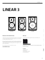 3
3
-
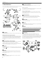 4
4
-
 5
5
-
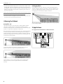 6
6
-
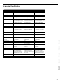 7
7
-
 8
8
-
 9
9
-
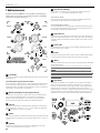 10
10
-
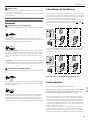 11
11
-
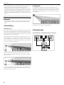 12
12
-
 13
13
-
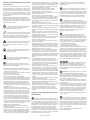 14
14
-
 15
15
-
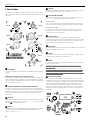 16
16
-
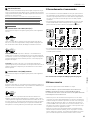 17
17
-
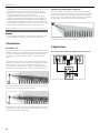 18
18
-
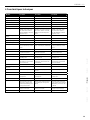 19
19
-
 20
20
-
 21
21
-
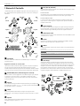 22
22
-
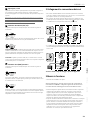 23
23
-
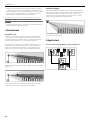 24
24
-
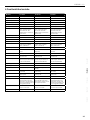 25
25
-
 26
26
-
 27
27
-
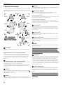 28
28
-
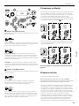 29
29
-
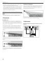 30
30
-
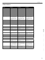 31
31
-
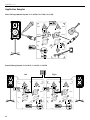 32
32
-
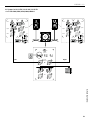 33
33
-
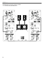 34
34
-
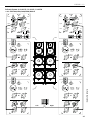 35
35
-
 36
36


HK Audio L3 112 FA Manuale utente
- Categoria
- Altoparlanti della soundbar
- Tipo
- Manuale utente
- Questo manuale è adatto anche per
in altre lingue
- English: HK Audio L3 112 FA User manual
- français: HK Audio L3 112 FA Manuel utilisateur
- español: HK Audio L3 112 FA Manual de usuario
- Deutsch: HK Audio L3 112 FA Benutzerhandbuch
Documenti correlati
-
HK Audio SOUNDCADDY ONE Manuale utente
-
-
-
HK Audio Linear 5 Manuale utente
-
-
-
HK Audio L SUB 2000 A Manuale utente
-
-
-