Thermo Scientific Revco Slimline Istruzioni per l'uso
- Tipo
- Istruzioni per l'uso


© 2007 Thermo Fisher Scientific. All rights reserved.
“Mylar®” is a registered trademark of DuPont.
“Suva®” is a registered trademark of DuPont.
All other trademarks are the property of Thermo Fisher Scientific Inc. and its subsidiaries.
2007 Thermo Fisher Scientific. All rights reserved.
“Suva®” is a registered trademark of DuPont.
All other trademarks are the property of Thermo Fisher Scientific Inc. and
its subsidiaries.

Thermo Scientific Revco Slimline Value Freezers Installation and Operation
i
Table of Contents
1 Introduction . . . . . . . . . . . . . . . . . . . . . . . . . . . . . . . . . . . . . . . . . . . . . . . . . . . . . . . . . . . . . . . . . . . . . . . 1
2 Safety Precautions . . . . . . . . . . . . . . . . . . . . . . . . . . . . . . . . . . . . . . . . . . . . . . . . . . . . . . . . . . . . . . . . . 1
3 Pre-Installation . . . . . . . . . . . . . . . . . . . . . . . . . . . . . . . . . . . . . . . . . . . . . . . . . . . . . . . . . . . . . . . . . . . . 1
3.1 Unpacking . . . . . . . . . . . . . . . . . . . . . . . . . . . . . . . . . . . . . . . . . . . . . . . . . . . . . . . . . . . . . . . . . . . . . . . . . . . . . . .1
4 General Recommendations . . . . . . . . . . . . . . . . . . . . . . . . . . . . . . . . . . . . . . . . . . . . . . . . . . . . . . . . . . 1
4.1 Initial Loading . . . . . . . . . . . . . . . . . . . . . . . . . . . . . . . . . . . . . . . . . . . . . . . . . . . . . . . . . . . . . . . . . . . . . . . . . . . .1
5 Installation . . . . . . . . . . . . . . . . . . . . . . . . . . . . . . . . . . . . . . . . . . . . . . . . . . . . . . . . . . . . . . . . . . . . . . . . 2
5.1 Location . . . . . . . . . . . . . . . . . . . . . . . . . . . . . . . . . . . . . . . . . . . . . . . . . . . . . . . . . . . . . . . . . . . . . . . . . . . . . . . .2
5.2 Wiring . . . . . . . . . . . . . . . . . . . . . . . . . . . . . . . . . . . . . . . . . . . . . . . . . . . . . . . . . . . . . . . . . . . . . . . . . . . . . . . . . .2
5.3 Superinsulated Cabinet Construction . . . . . . . . . . . . . . . . . . . . . . . . . . . . . . . . . . . . . . . . . . . . . . . . . . . . . . . . . .2
5.4 Leveling . . . . . . . . . . . . . . . . . . . . . . . . . . . . . . . . . . . . . . . . . . . . . . . . . . . . . . . . . . . . . . . . . . . . . . . . . . . . . . . .2
6 Pressure Equalization Port . . . . . . . . . . . . . . . . . . . . . . . . . . . . . . . . . . . . . . . . . . . . . . . . . . . . . . . . . . 3
7 Operation . . . . . . . . . . . . . . . . . . . . . . . . . . . . . . . . . . . . . . . . . . . . . . . . . . . . . . . . . . . . . . . . . . . . . . . . . 4
7.1 Control Panel Features . . . . . . . . . . . . . . . . . . . . . . . . . . . . . . . . . . . . . . . . . . . . . . . . . . . . . . . . . . . . . . . . . . . . .4
7.2 Start Up . . . . . . . . . . . . . . . . . . . . . . . . . . . . . . . . . . . . . . . . . . . . . . . . . . . . . . . . . . . . . . . . . . . . . . . . . . . . . . . .4
7.2.1 Turning the Power On . . . . . . . . . . . . . . . . . . . . . . . . . . . . . . . . . . . . . . . . . . . . . . . . . . . . . . . . . . . . . . .4
7.2.2 Setting the Cabinet Temperature . . . . . . . . . . . . . . . . . . . . . . . . . . . . . . . . . . . . . . . . . . . . . . . . . . . . . . .4
7.2.3 Alarm . . . . . . . . . . . . . . . . . . . . . . . . . . . . . . . . . . . . . . . . . . . . . . . . . . . . . . . . . . . . . . . . . . . . . . . . . . . .4
8 Maintenance and Troubleshooting . . . . . . . . . . . . . . . . . . . . . . . . . . . . . . . . . . . . . . . . . . . . . . . . . . . . 5
8.1 Condenser Maintenance . . . . . . . . . . . . . . . . . . . . . . . . . . . . . . . . . . . . . . . . . . . . . . . . . . . . . . . . . . . . . . . . . . . .5
8.1.1 Cleaning the Condenser . . . . . . . . . . . . . . . . . . . . . . . . . . . . . . . . . . . . . . . . . . . . . . . . . . . . . . . . . . . . .5
8.1.2 Cleaning the Condenser Filter . . . . . . . . . . . . . . . . . . . . . . . . . . . . . . . . . . . . . . . . . . . . . . . . . . . . . . . . .5
8.2 Gasket Maintenance . . . . . . . . . . . . . . . . . . . . . . . . . . . . . . . . . . . . . . . . . . . . . . . . . . . . . . . . . . . . . . . . . . . . . . .5
8.3 Defrost Procedures . . . . . . . . . . . . . . . . . . . . . . . . . . . . . . . . . . . . . . . . . . . . . . . . . . . . . . . . . . . . . . . . . . . . . . . .5
8.4 Alarm Battery Maintenance . . . . . . . . . . . . . . . . . . . . . . . . . . . . . . . . . . . . . . . . . . . . . . . . . . . . . . . . . . . . . . . . .5
9 Chart Recorders . . . . . . . . . . . . . . . . . . . . . . . . . . . . . . . . . . . . . . . . . . . . . . . . . . . . . . . . . . . . . . . . . . . 6
9.1 Set Up and Operation . . . . . . . . . . . . . . . . . . . . . . . . . . . . . . . . . . . . . . . . . . . . . . . . . . . . . . . . . . . . . . . . . . . . . .6
9.2 Power Supply . . . . . . . . . . . . . . . . . . . . . . . . . . . . . . . . . . . . . . . . . . . . . . . . . . . . . . . . . . . . . . . . . . . . . . . . . . . .6
9.3 Changing Chart Paper . . . . . . . . . . . . . . . . . . . . . . . . . . . . . . . . . . . . . . . . . . . . . . . . . . . . . . . . . . . . . . . . . . . . .6
9.4 Calibration Adjustment . . . . . . . . . . . . . . . . . . . . . . . . . . . . . . . . . . . . . . . . . . . . . . . . . . . . . . . . . . . . . . . . . . . . .6
10 Optional Equipment . . . . . . . . . . . . . . . . . . . . . . . . . . . . . . . . . . . . . . . . . . . . . . . . . . . . . . . . . . . . . . . . 7
10.1Voltage Safeguard . . . . . . . . . . . . . . . . . . . . . . . . . . . . . . . . . . . . . . . . . . . . . . . . . . . . . . . . . . . . . . . . . . . . . . . .7
10.2Remote Alarm . . . . . . . . . . . . . . . . . . . . . . . . . . . . . . . . . . . . . . . . . . . . . . . . . . . . . . . . . . . . . . . . . . . . . . . . . . . .7
11 Accessories . . . . . . . . . . . . . . . . . . . . . . . . . . . . . . . . . . . . . . . . . . . . . . . . . . . . . . . . . . . . . . . . . . . . . . . 7

Thermo Scientific Revco Slimline Value Freezers Installation and Operation
1
1 Introduction
Revco® Slimline Value -86ºC upright freezers feature the use of
vacuum insulation technology to minimize wall thickness and
provide extra storage space. Because of the thin wall
construction, SI models can hold more inventory than
conventional models that take up the same lab space.
Standard features include:
•High storage capacity — up to 15 inventory racks
•Separately mounted inner doors with adjustable hinges for
each door
•A pressure equalization port to combat the vacuum created
after door openings
SI Series freezers use the Legaci™ refrigeration system. a
combination of advanced technologies designed specifically to
provide optimal reliability in low-temperature applications.
Legaci systems include:
•Copeland compressors custom-designed to minimize bearing
wear and operate efficiently under heavy work loads
•Dupont Suva® refrigerants selected to provide maximum
cooling capacity under low-temperature conditions
•A field-proven cascade refrigeration system design.
2 Safety Precautions
In this manual and on labels attached to this product, the words
WARNING and CAUTION mean the following:
•WARNING: a potentially hazardous situation which, if not
avoided, could result in serious injury or death.
•CAUTION: a potentially hazardous situation which, if not
avoided, may result in minor or moderate injury or damage to
the equipment.
Before installing, using or maintaining this product, please be sure
to read this manual and product warning labels carefully. Failure to
follow these instructions may cause this product to malfunction,
which could result in injury or damage.
Below are important safety precautions that apply to this product:
•Use this product only in the way described in the product
literature and in this manual. Before using it, verify that this
product is suitable for its intended use.
•Do not modify system components, especially the controller.
Use OEM exact replacement equipment or parts. Before use,
confirm that the product has not been altered in any way.
•Your unit must be properly grounded in conformity with
national and local electrical codes. Never connect the unit to
overloaded power sources.
•Disconnect the unit from all power sources before cleaning,
troubleshooting, or performing other maintenance on the
product or its controls.
3 Pre-Installation
3.1 Unpacking
At delivery, examine the exterior for physical damage while the
carrier’s representative is present. If exterior damage is
present, carefully unpack and inspect the unit and all
accessories for damage.
If there is no exterior damage, unpack and inspect the
equipment within five days of delivery. If you find any damage,
keep the packing materials and immediately report the damage
to the carrier. Do not return goods without written
authorization. When submitting a claim for shipping damage,
request that the carrier inspect the shipping container and
equipment.
4 General Recommendations
This refrigeration system is designed to maintain ultra-low
temperatures with safety in a +32°C (90°F) ambient
environment, only when the freezer is used for storage.
WARNING! This unit is not a “rapid-freeze” device.
Freezing large quantities of liquid, or high-water
content items, will temporarily increase the chamber
temperature and will cause the compressors to
operate for a prolonged time period.
Avoid opening the door for extended time periods since chamber
temperature air will escape rapidly. Room air, which is higher in
humidity, replacing chamber air may cause frost to develop in the
chamber more rapidly.
4.1 Initial Loading
After reading and completing the Safety Considerations,
Pre-Installation, Installation, and Operation sections of this
manual, turn the Key Switch to the POWER ON position and
adjust the temperature setpoint if necessary.
The setpoint should be no warmer than -50ºC. Allow the freezer
to operate at the desired temperature for a minimum of 12
hours before loading.
Load the freezer one shelf at a time, beginning with the top shelf.
After loading each shelf, allow the freezer to recover to the
desired setpoint before loading the next shelf. Repeat this process
until the freezer is fully loaded.
CAUTION! Failure to follow these procedures or
overloading the unit may cause undue stress on the
compressors or jeopardize user product safety.

Thermo Scientific Revco Slimline Value Freezers Installation and Operation
2
5 Installation
Do not exceed the electrical and temperature ratings printed on
the dataplate located on the lower left side of the unit.
CAUTION! Improper operation of the equipment
could result in dangerous conditions. To preclude
hazard and minimize risk, follow all instructions and
operate within the design limits noted on the dataplate.
5.1 Location
Install the unit in a level area free from vibration with a minimum
of six inches of space on the sides, rear, and top. Refer to
Section 5.4 for further instructions on leveling cabinets. Allow
enough clearance so that door or lid can swing open at least
90 degrees.
Do not position the equipment in direct sunlight or near heating
diffusers, radiators, or other sources of heat. The ambient
temperature range at the location must be 59 to 90°F
(15to32°C).
CAUTION! To allow for proper air flow, a minimum
of six inches of clearance space is required behind the
freezer.
5.2 Wiring
CAUTION! Connect the equipment to the correct
power source. Incorrect voltage can result in severe
damage to the equipment.
CAUTION! For personal safety and trouble-free
operation, this unit must be properly grounded before
it is used. Failure to ground the equipment may cause
personal injury or damage to the equipment. Always
conform to the National Electrical Code and local
codes. Do not connect the unit to overloaded power
lines.
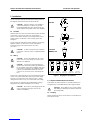
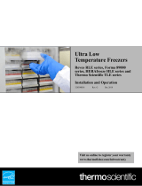
Your freezer is equipped with a service cord and plug designed to
connect it to a power outlet which delivers the correct voltage.
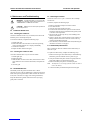
The plug is one of the three types shown in Figure 1. Supply
voltage must be within +10%, -5% of the freezer rated voltage.
These freezers are equipped with a standard built-in Voltage
Safeguard circuit to detect and adjust low line voltage.
CAUTION! Never cut the grounding prong from the
service cord plug. If the prong is removed, the
warranty is invalidated.
Figure 1. Plug Styles for SI Models
5.3 Superinsulated Cabinet Construction
In SI models, the cabinet walls have a vacuum insulation core
encapsulated by a sealed film laminate and wrapped in Mylar.
CAUTION! Never drill holes in or near the cabinet
walls. Drilling could damage the insulation and make
the unit inoperable.
5.4 Leveling
Before operating the freezer, be sure that it is level both front to
back and side to side.
220 VAC
240 VAC
Built-in
13 Amp Fuse
15A-250V
NEMA 6-15P
15A-125V
NEMA 5-15P
20A-125V
NEMA 5-20P
15A-250V
NEMA 6-15P
20A-250V
NEMA 6-20P
30A-250V
NEMA 6-30P

Thermo Scientific Revco Slimline Value Freezers Installation and Operation
3
6 Pressure Equalization Port
When an upright ultra-low temperature freezer door is opened,
room temperature air rushes into the storage compartment.
When the door is closed, the fixed volume of air is cooled
rapidly. Pressure drops below atmospheric pressure, resulting in
a substantial vacuum. Re-entry into the cabinet is impossible
until internal pressures are returned to atmospheric pressure.
Without a pressure equalization mechanism, it can take several
minutes before the door can easily be reopened.
SI Series models feature a port that provides vacuum relief
within 30 seconds after door openings. To minimize warm air
entry, the port automatically closes as soon as pressures are
equalized.
The pressure equalization port is located on the right side of the
storage chamber. Although the port is designed to self-defrost,
excessive frost accumulation in the bottom of the chamber could
eventually restrict air flow. Therefore you should periodically
inspect the port and brush away any loose frost using a stiff nylon
brush.
WARNING! Because the defrost heater for the
pressure equalization port operates continuously, the
surfaces near the port can get hot if the unit is plugged
in but the freezer is not in use. You can avoid this by
unplugging the freezer when it is not being used for
cold storage.
WARNING! Always wear proper gloves to protect
the skin when working inside ultra-low temperature
freezers.

Thermo Scientific Revco Slimline Value Freezers Installation and Operation
4
7 Operation
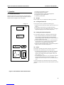
7.1 Control Panel Features
Before the initial start up, take some time to become familiar
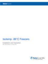
with the controls on your freezer. Figure 2 illustrates the Revco
Slimline Value SI Upright Freezer control panel.
Figure 2. Revco Slimline Value SI Control Panel
1. Keyed Power On/Alarm On switch.
2. LED digital temperature display.
3. Recessed temperature control setpoint adjustment.
4. Temperature setpoint adjust button.
5. Calibration potentiometer.
7. 2 S t a r t U p
Refer to Figure 2 as you complete the following procedures.
7.2.1 Turning the Power On
To start up the freezers, complete the following steps:
1. Plug the freezer into the power outlet (refer to Section 5.2 on
page 2).
2. Verify that the alarm switch is in the MUTE position.
3. Turn the key switch to the POWER ON position. The digital
temperature display shows the cabinet temperature.
7.2.2 Setting the Cabinet Temperature
To set the cabinet temperature, complete the following steps:
1. Insert a small screwdriver into the slotted screw labeled
Control Setpoint and simultaneously press and hold the
Setpoint Display button. The temperature display changes to
read the existing setpoint value.
2. Turn the setpoint screw (clockwise for a colder setting and
counterclockwise for a warmer setting) until the desired
setpoint shows in the digital temperature display.
3. Release the Setpoint Display button. The digital temperature
display returns to the cabinet temperature.
7. 2 . 3 A l a r m
The alarm is operated by the freezer electronic control system.
The alarm is preset at the factory with a warm setpoint:
•For units designed to operate at -75°C and -85°C, the alarm
setpoint is approximately 90% of the freezer temperature
setpoint. For example, if the freezer setpoint is -80°C, the
alarm setpoint is -72°C.
•For units designed to operate at -50°C and warmer, the alarm
setpoint is 80% of the freezer temperature setpoint. For
example, if the freezer setpoint is -45°C, the alarm setpoint is
-36°C.
To activate the alarm, wait until the freezer reaches operating
temperature and flip the alarm switch from the MUTE to the ON
position.
ºC
display set point
control set point ºC Failure
Off Power
On
Alarm mute
calibration pot.

Thermo Scientific Revco Slimline Value Freezers Installation and Operation
5
8 Maintenance and Troubleshooting
WARNING! Unauthorized repair of your freezer will
invalidate your warranty. Contact Technical Service at
1-800-438-4851 for additional information.
CAUTION! Maintenance should only be performed
by trained personnel.
8.1 Condenser Maintenance
8.1.1 Cleaning the Condenser
Clean the condenser at least every six months; more often if the
laboratory area is extremely dust prone.
To clean the condenser, complete the following steps:
1. Pull the grill open.
2. Remove the filter. Check the fans. If a fan is not operating,
contact an Authorized Service Company immediately.
3. Vacuum the condenser.
4. Replace the filter and close the grill.
8.1.2 Cleaning the Condenser Filter
Clean the condenser filter every two or three months.
1. Pull the grill open.
2. Remove the filter.
3. Shake the filter to remove loose dust, rinse the filter in clean
water, shake the excess water from the filter, and replace the
filter.
4. Close the grill.
8.2 Gasket Maintenance
Periodically check the gaskets around the door or lid for
punctures or tears. Leaks are indicated by a streak of frost which
forms at the point of gasket failure. Make sure that the cabinet is
level (refer to Section 5.4 on page 2 for leveling information).
Keep the lid and door gaskets clean and frost free by wiping
gently with a soft cloth.
8.3 Defrosting the Freezer
Defrost the freezer once or year or whenever the ice buildup
exceeds 3/8”.
To defrost, complete the following steps:
1. Remove all products and place in another cabinet.
2. Turn off the freezer.
3. Open the outer door and all inner doors.
4. Let the freezer stand with doors open for at least 24 hours.
This allows both the interior and foamed refrigerant system
to warm to room temperature.
5. Dispose of the ice and wipe out any water standing in the
bottom of the cabinet.
6. If there is freezer odor, wash the interior with a solution of
baking soda and warm water. Clean the exterior with any
common household cleaning wax.
7. Close the doors, restart the freezer and reload, following the
instructions in Section 4.1 on page 1.
8.4 Alarm Battery Maintenance
Have a technician check the condition of the alarm battery at
least once a year.
To replace the alarm battery, complete the following steps:
1. Remove the front grill. The alarm battery is located directly
behind the grill. The terminals are the “push on” type.
2. Grasp the terminal with pliers and work it gently back and
forth while pulling it off. The fittings are tight.
3. Remove the battery and put the new battery in place.
Note: You may have to cut a strip of silicone rubber in order to
remove the battery.
4. Connect the battery terminals and replace the front grill.

Thermo Scientific Revco Slimline Value Freezers Installation and Operation
6
9 Chart Recorders
Panel-mounted six-inch seven-day recorders are available as
options for all freezer models.
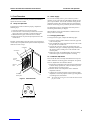
9.1 Set Up and Operation
To prepare the recorder to function properly, complete the
following steps:
1. Open the recorder door to access the recorder.
2. Connect the nine volt DC battery located at the recorder’s
upper right corner. This battery provides backup power.
3. Install clean chart paper (refer to Section 9.3 below).
4. Remove the plastic cap from the pen stylus and close the
recorder door.
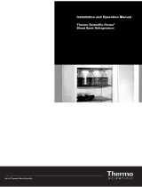
Recorder operation begins when the system is powered on.The
recorder may not respond until the system reaches temperatures
within the recorder’s range.
Figure 3. Chart Recorder
Figure 4. Chart Buttons
9 Volt Battery
Imprinting
Stylus
Hub-Nut and
Retaining Wire
Chart
Chart Buttons
Reference
Mark
12
3
CHANGE CHART
9.2 Power Supply
The recorder normally uses AC power when the system is
operating. If AC power fails, the LED indicator flashes to alert
you to a power failure. The recorder continues sensing cabinet
temperature and the chart continues turning for approximately
24 hours with back-up power provided by the nine-volt battery.
The LED indicator glows continuously when main power is
functioning and the battery is charged.
When the battery is low, the LED flashes to indicate that the
battery needs to be changed.
9.3 Changing Chart Paper
To change the chart paper, complete the following steps:
1. Locate the pressure sensitive buttons at the front, upper left
of the recorder panel.
2. Press and hold the Change Chart button (#3) for one second.
The pen will move off the scale.
3. Unscrew the center nut, remove the old chart paper, and
install new chart paper. Carefully align the day and time with
the reference mark (a small groove on the left side of the
recorder panel).
4. Replace the center nut and hand tighten. Press the Change
Chart button again to resume temperature recording.
9.4 Calibration Adjustment
This recorder has been accurately calibrated at the factory and
retains calibration even during power interruptions. If required,
however, adjustments can be made as follows:
1. Run the unit continuously at the control setpoint temperature.
Continue steady operation for at least two hours to provide
adequate time for recorder response.
2. Measure cabinet center temperature with a calibrated
temperature monitor.
3. Compare the recorder temperature to the measured cabinet
temperature. If necessary, adjust recorder by pressing the left
(#1) and right (#2) chart buttons.
Note: The stylus does not begin to move until the button is held
for five seconds.

Thermo Scientific Revco Slimline Value Freezers Installation and Operation
7
10 Optional Equipment
In addition to the optional chart recorder, the following
equipment is available for some freezer models. Refer to the
Accessories for more information on these and other options,
including inventory racks and storage boxes.
For additional information, contact your dealer or Customer sales
at 1-800-252-7100.
10.1 Voltage Safeguard
This fully automatic device monitors the supply voltage and
increases voltage if necessary so the freezer always operates
within the factory recommended limits.
CAUTION! The Voltage Safeguard unit does not
allow you to operate a 115 volt product on 230 volts or
vice versa. It is designed to provide 5 to 15% voltage
correction, depending on the freezer model.
10.2 Remote Alarm
The remote alarm terminals on the back of the freezer are
connected to freezer internal dry contacts. You can connect a
remote alarm package with a separate 24 volt power supply.
11 Accessories
Note: For accessories and options not described herein, or for
special modifications, contact Customer Sales.
Inventory Component Description, Ultra-Low Temperature
Freezers
Temperature Recorders
All six inch recorders utilize pressure-sensitive chart paper
(1 box @ 50 charts included); no inking is required.
Chart Paper
Surge Suppressor
Alarm Systems
Remote Alarm/Monitoring
Description Catalog
No.
For All Models
Fiberboard boxes and grid dividers are packaged in lots of one
dozen
Fiberboard box, 5-1/4 in. square x 2 in. high, one dozen. 5954
Fiberboard box, 5-1/4 in. square x 3 in. high, one dozen. 5956
Grid divider, fiberboard, 100 cell, 7/16 in., holds 100 12 mm
vials, one dozen. 5958
Grid divider, fiberboard, 49 cell, 5/8 in., holds 49 16 mm
vials, one dozen. 5959
Grid divider, fiberboard, 64 cell, 9/16 in., holds 64 14 mm
vials, one dozen. 5960
Grid divider, fiberboard, 81 cell, 1/2 in., holds 81 13 mm
vials, one dozen. 6212
Adjustable single stack, holds (16) 2 in. or (12) 3 in. boxes.
6112-1
Solid stainless steel shelf: 6670
Description Catalog
No.
Temperature recorder, 6 in. circular chart, seven-day drive,
panel mounted. Factory installed. 6183
Temperature recorder, 6 in. circular chart, seven-day drive,
free-standing, Customer installed.
6383
Description Catalog
No.
Chart paper, package of 50, for 6 in., seven-day recorder,
-115°Cto +50°C. 6185
Description Catalog
No.
Surge Suppressor, free standing. 6185
Description Catalog
No.
Deluxe Electronic Remote Alarm System. User
programmable to sound alarm in the event of
temperature rise or power failure. Can dial up to four
telephone numbers to advise of alarm condition across
any telephone system which accepts pulse dialing.
One system can monitor up to four individual freezers
or up to three groups of freezers. Contact Customer
Sales for detailed specifications. 6224

8
Thermo Scientific Revco Slimline Value Freezers Installation and Operation
WEEE Compliance
WEEE Compliance. This product is required to comply with the European
Union’s Waste Electrical & Electronic Equipment (WEEE) Directive 2002/96EC.
It is marked with the following symbol. Thermo Fisher Scientific has contracted
with one or more recycling/disposal companies in each EU Member State, and this
product should be disposed of or recycled through them. Further information on
Thermo Fisher Scientific compliance with these Directives, the recyclers in your
country, and information on Thermo Scientific products which may assist the
detection of substances subject to the RoHS Directive are available at
www.thermo.com/
WEEE Konformittät. Dieses Produkt muss die EU Waste Electrical & Electronic
Equipment (WEEE) Richtlinie 2002/96EC erfüllen. Das Produkt ist durch
folgendes Symbol gekennzeichnet. Thermo Fisher Scientific hat Vereinbarungen
getroffen mit Verwertungs/Entsorgungsanlagen in allen EU-Mitgliederstaaten und
dieses Produkt muss durch diese Firmen widerverwetet oder entsorgt werden.
Mehr Informationen über die Einhaltung dieser Anweisungen durch Thermo
Fisher Scientific, die Verwerter und Hinweise die Ihnen nützlich sein können, die
Thermo Scientific Produkte zu identifizieren, die unter diese RoHS.
Anweisungfallen, finden Sie unter www.thermo.com/
Conformità WEEE. Questo prodotto deve rispondere alla direttiva dell’ Unione
Europea 2002/96EC in merito ai Rifiuti degli Apparecchi Elettrici ed Elettronici
(WEEE). È marcato col seguente simbolo.Thermo Fisher Scientific ha stipulato
contratti con una o diverse società di riciclaggio/smaltimento in ognuno degli Stati
Membri Europei. Questo prodotto verrà smaltito o riciclato tramite queste
medesime. Ulteriori informazioni sulla conformità di Thermo Fisher Scientific con
queste Direttive, l’elenco delle ditte di riciclaggio nel Vostro paese e informazioni
sui prodotti Thermo Scientific che possono essere utili alla rilevazione di sostanze
soggette alla Direttiva RoHS sono disponibili sul sito www.thermo.com/
Conformité WEEE. Ce produit doit être conforme à la directive européenne
(2002/96EC) des Déchets d’Equipements Electriques et Electroniques (DEEE). Il
est marqué par le symbole suivant. Thermo Fisher Scientific s’est associé avec une
ou plusieurs compagnies de recyclage dans chaque état membre de l’union
européenne et ce produit devraitêtre collecté ou recyclé par celles-ci. Davantage
d’informations sur laconformité de Thermo Fisher Scientific à ces directives, les
recycleurs dans votre pays et les informations sur les produits Thermo Scientific
qui peuvent aider le détection des substances sujettes à la directive RoHS sont
disponibles sur www.thermo.com/
Great Britain
Deutschland
France
Italia

Important
For your future reference and when contacting the factory, please have the
following information readily available:
Model Number:
Serial Number:
Date Purchased:
The above information can be found on the dataplate attached to the
equipment. If available, please provide the date purchased, the source of
purchase (manufacturer or specific agent/rep organization), and purchase
order number.
IF YOU NEED ASSISTANCE:
SALES DIVISION
Phone: 828/658-2711
800/252-7100
FAX: 828/645-3368
LABORATORY PARTS and SERVICE
Phone: 800/438-4851
FAX: 828/658-2576
TECHNICAL SUPPORT
Phone: 800/438-4851

-
 1
1
-
 2
2
-
 3
3
-
 4
4
-
 5
5
-
 6
6
-
 7
7
-
 8
8
-
 9
9
-
 10
10
-
 11
11
-
 12
12
-
 13
13


Thermo Scientific Revco Slimline Istruzioni per l'uso
- Tipo
- Istruzioni per l'uso
in altre lingue
Documenti correlati
Altri documenti
-
 Thermo Fisher Scientific Adv Manuale utente
-
 Thermo Fisher Scientific Adv Manuale utente
-
Thermo Fisher Scientific TSX Manuale utente
-
-
 Thermo Fisher Scientific ULT Manuale del proprietario
-
Phcbi MDF-U5412H-PE Istruzioni per l'uso
-
 Thermo Fisher Scientific ULT Manuale del proprietario
-
 Thermo Fisher Scientific ULT Manuale del proprietario
-
-
 Thermo Fisher Scientific Forma Manuale del proprietario


