Lindy Video over IP Controller Guida d'installazione
- Tipo
- Guida d'installazione

© LINDY Group - SECOND EDITION (March 2019)
Video Over IP Controller
Quick Installation Guide English
Schnellstartanleitung Deutsch
Guide d’Installation Rapide Français
Guida di installazione rapida Italiano
No. 38263
lindy.com
Tested to comply with FCC
Standards
For Commercial Use Only!!


User Manual English
Introduction
Thank you for purchasing the Video Over IP Controller. This product has been designed to provide trouble free,
reliable operation. It benefits from both a LINDY 2 year warranty and free lifetime technical support. To ensure correct
use, please read this manual carefully and retain it for future reference.
This Video Over IP Controller enables the management and configuration of multiple Video over IP (VoIP) extenders
(No.38266 and 38267) through a single WebGUI, that provides the complete status of all connected transmitters
(No.38266) and receivers (No.38267), including IP address, channel selection and video preview. It also features
local console ports including an HDMI output and one USB port for the connection of a keyboard or mouse (or both
via a USB hub), to view and interact with the WebGUI.
Package Contents
Video Over IP Controller
Multi-country 5V DC 2.6A PSU, 5.5mm / 2.1mm with EU, UK, US and AUS adapters
1 x terminal block (3-pin)
3 x terminal block (5-pin)
3.5mm to IR extender cable
Remote control (with included CR2025 battery)
4 x rubber feet
OSS statement
Lindy QIG (Quick Installation Guide)
Features
Enables the management and configuration of multiple Video over IP (VoIP) extender (No.38266 and 38267)
through a single WebGUI
Supports point-to-point (unicast) and multipoint-to-multipoint (multicast) routing selections
Controls both Matrix and TV wall configurations using WebGUI presets
Definable display groups to simplify large installations
WebGUI provides the complete status of all connected transmitters (No.38266) and receivers (No.38267),
including IP address, channel selection and video preview.
Local console featuring an HDMI output and one USB port for the connection of a keyboard or mouse (or both
via a USB hub), to view and interact with the WebGUI
Specifications
Control modes: WebGUI (remote or local), RS-232, Telnet, Trigger and IR Remote
RJ45 Gigabit Ethernet port with PoE support (802.3af)
Output port: 1 x HDMI Female (resolution: 1920x1080@60Hz)
Control ports: 1 x RS232 (3 pin terminal block), 8 x Trigger Contacts (10 pin terminal block), 1 x USB Type A
Female, 2 x RJ45, 1 x Factory Reserved Connector (5 pin terminal block)
IR Frequency: 30 – 50kHz
Power Consumption: 2.99 W
Operating Temperature: 0°C - 40°C (32°F - 104°F)
Storage Temperature: -20°C - 60°C (-4°F - 140°F)
Operating Humidity: 20% - 90% (non-condensing)
Storage Humidity: 20% - 90% (non-condensing)

User Manual English
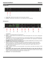
Overview
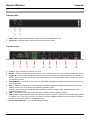
Front Panel
1. Power LED – Flashes during power up and stays illuminated whilst the unit is operating.
2. IR Eye – Receives the IR signal from the included IR remote control
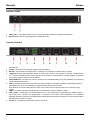
Rear Panel
1. IR Ext - Connects to the provided IR extender to extend the IR control range of the unit.
2. Control – Socket reserved for factory updates
3. RS-232 – Serial socket to be connected with a serial controller or PC through the supplied terminal
4. Trigger IN: Connects any trigger device (not supplied) such as, control keypads, security alarms, door switches,
etc. Each of the 8 trigger inputs can be used to activate an associated preset. The trigger needs a minimum of
5V to be activated
5. HDMI OUT port – Connects a display with a standard HDMI cable (not included) used for direct local monitoring
/ management of the unit.
6. USB: Connects a USB mouse and/or keyboard to control the unit’s WebGUI displayed on the HDMI output
port. Firmware update via USB is also supported.
Note: Specialized USB control devices, such as a touch panel, should be connected before the unit is
powered on.
7. LAN 2 – Connect this port to the network used to control the unit via WebGUI / Telnet
8. LAN 1 (PoE) – This port must be connected to the network where all the controlled units (No. 38266 and 38267
– not included) are connected to. If this port is connected to an IEEE802.3af. compliant switch the unit can get
power directly from it avoiding to use the included PSU.
9. DC Power socket – Attach the supplied PSU here.

User Manual English
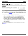
IR Extender
IR Receiver cable for the connection with the IR Ext port
Remote Control
The included remote control has 8 buttons that recall an associated
preset allowing the user to quickly change the screen layout.
Installation
Please note: This is a Quick Installation Guide which includes basic information only. All the configuration settings
and function controls of this system can be accessed through the Web interface embedded in all the units. Please
refer to the full manual published on the product’s page (www.lindy.com) for further details.
Please follow the following steps to install the Video over IP Controller:
1. Please make sure that all the devices included in the installation are shut down
2. Connect, as required, the HDMI, USB (for keyboard and mouse or control devices only), Serial and Trigger
ports on the unit to the devices you want to attach to this system using standard cables.
3. Connect, as required, the IR extender cable to the IR EXT port
4. Connect a standard RJ45 Ethernet cable to the “LAN 2” port and to the network where the (No. 38266 and
38267) units are connected to. If you are connecting the units to a Gigabit PoE (IEEE 802.3af compliant) switch
you can skip step 6 and avoid using the supplied PSU.
5. Connect a standard RJ45 Ethernet cable to the “LAN 1 (PoE)” port to the network where the used control PC
to is connected to.
6. Connect (if required) the supplied PSU DC plug to the DC 5V ports
7. Turn on all the connected devices.
Now all the connections are made and the system is ready to be configured and distribute the managed signals.
Please refer to the full manual published on the product’s page (www.lindy.com) to proceed with a detailed
configuration.

Benutzerhandbuch Deutsch
Einführung
Wir freuen uns, dass Ihre Wahl auf ein LINDY-Produkt gefallen ist und danken Ihnen für Ihr Vertrauen. Sie können
sich jederzeit auf unsere Produkte und einen guten Service verlassen. Dieser Video over IP Controller unterliegt
einer 2-Jahres LINDY Herstellergarantie und lebenslangem kostenlosen, technischen Support. Bitte lesen Sie
diese Anleitung sorgfältig und bewahren Sie sie auf.
Dieser Video Over IP Controller erlaubt die Verwaltung und Konfiguration mehrerer Video over IP (VoIP) Extender
(No.38266 und 38267) über ein einziges WebGUI, welches den kompletten Status aller angeschlossenen
Transmitter (No.38266) und Receiver (No.38267) inklusive IP-Adresse, Auswahl des Kanals und Videovorschau
liefert. Der Controller verfügt über lokale Konsolenports inklusive eines HDMI-Ausgangs und eines USB Ports für
Tastatur- und Mausanschluss (oder beider über einen USB Hub) für die Ansicht und Interaktion mit dem WebGUI.
Lieferumfang
Video Over IP Controller
Multi-Country 5V DC 2.6A Netzteil, 5.5mm / 2.1mm mit Adaptern (EU, UK, US und AUS)
1 x Terminal Block (3 Pin)
3 x Terminal Block (5 Pin)
3.5mm an IR-Verlängerungskabel
Fernbedienung (mit CR2025-Batterie)
4 x Gummifüße
OSS-Erklärung
Lindy Kurzanleitung
Eigenschaften
Ermöglicht Verwaltung und Konfiguration mehrerer Video over IP (VoIP) Extender (No.38266 und 38267) über
ein einziges WebGUI
Unterstützt Punkt-zu-Punkt (Unicast) und Mehrpunkt-zu-Mehrpunkt (Multicast) Routing
Steuert Matrix- und TV-Wand-Konfigurationen mithilfe von WebGUI-Voreinstellungen
Definierbare Displaygruppen zum Vereinfachen großer Installationen
WebGUI liefert kompletten Status aller angeschlossenen Transmitter (No.38266) und Receiver (No.38267)
inklusive IP-Adresse, Auswahl des Kanals und Videovorschau
Lokale Konsole mit HDMI-Ausgang und USB Port für Tastatur- und Mausanschluss (oder beider über einen USB
Hub) für die Ansicht und Interaktion mit dem WebGUI
Spezifikationen
Steuermodi: WebGUI (remote oder lokal), RS-232, Telnet, Trigger und IR-Fernbedienung
RJ45 Gigabit Ethernet Port mit PoE-Unterstützung (802.11af)
Ausgangsport: 1 x HDMI-Buchse (Auflösung: 1920x1080@60Hz)
Steuerports: 1 x RS232 (3 Pin Terminal Block), 8 x Trigger-Kontakte (10 Pin Terminal Block), 1 x USB-Buchse
Typ A, 2 x RJ45, 1 x werksseitig reservierter Anschluss (5 Pin Terminal Block)
IR-Frequenz: 30 – 50kHz
Stromverbrauch: 2.99 W
Betriebstemperatur: 0°C - 40°C (32°F - 104°F)
Lagertemperatur: -20°C - 60°C (-4°F - 140°F)
Luftfeuchtigkeit (im Betrieb): 20% - 90% (nicht-kondensierend)
Luftfeuchtigkeit (bei Lagerung): 20% - 90% (nicht-kondensierend)

Benutzerhandbuch Deutsch
Übersicht
Frontansicht
1. Power LED – Blinkt beim Einschalten und leuchtet weiter im Betrieb
2. IR-Auge – Empfängt das Infrarotsignal von der beiliegenden IR-Fernbedienung
Rückansicht
1. IR Ext – Zum Anschluss der beiliegenden IR-Verlängerung, um den Steuerbereich der Fernbedienung
auszudehnen
2. Control – Für Herstellerupdates reservierte Buchse
3. RS-232 – Serielle Buchse zum Anschluss eines seriellen Steuergeräts oder PCs über die beiliegenden
Terminal Blocks
4. Trigger IN: Zum Anschluss eines Triggergeräts (nicht im Lieferumfang enthalten) wie z.B. Tastatursteuerung,
Alarmkontakte usw. mit dem beiligenden Terminal Block zum Aktivieren einer zugehörigen Voreinstellung.
Der Trigger benötigt zur Aktivierung mindestens 5V.
5. HDMI OUT Port – Zum Anschluss eines Displays mit einem Standard-HDMI-Kabel (nicht enthalten), welches
zur direkten lokalen Überwachung / Verwaltung dient
6. USB: Zum Anschluss von USB-Maus und -Tastatur zum Steuern des WebGUI, das über den HDMI-
Ausgang angezeigt wird. Auch Firmwareupdates werden über den USB Port unterstützt. Beachten Sie
bitte, dass spezielle USB-Steuergeräte wie Touch Panels angeschlossen werden sollten, bevor der
Controller eingeschaltet wird.
7. LAN 2 – Verbinden Sie diesen Port mit dem Netzwerk, das zum Steuern des Geräts über WebGUI / Telnet
verwendet wird
8. LAN 1 (PoE) – Dieser Port muss mit dem Netzwerk verbunden werden, mit dem auch alle Geräte, die
gesteuert werden (No. 38266 und 38267 – nicht enthalten) verbunden sind. Wenn dieser Port mit einem
IEEE802.3af.2003-kompatiblen Switch verbunden ist, kann das Gerät direkt von diesem mit Strom versorgt
werden, so dass man das beiliegende Netzteil nicht verwenden muss.
9. DC-Buchse – Zum Anschluss des Netzteils

Benutzerhandbuch Deutsch
IR-Verlängerung
IR-Receiverkabel zur Verbindung mit den IR EXT Ports
Fernbedienung
Die beiliegende Fernbedienung verfügt über 8 Drucktasten, welche
Voreinstellungen abrufen, um Änderungen des Bildschirmlayouts zu
beschleunigen.
Installation
Beachten Sie bitte, dass diese Kurzanleitung nur grundlegende Informationen beinhaltet. Auf alle
Konfigurationseinstellungen und Funktionssteuerungen dieses Systems kann über die Webschnittstelle zugegriffen
werden, die in allen Geräten integriert ist. Das komplette Handbuch mit detaillierten Informationen finden Sie im Lindy
Webshop auf der Produktseite (www.lindy.com).
Zur Installation des Video over IP Controllers gehen Sie bitte folgendermaßen vor:
1. Stellen Sie sicher, dass alle Geräte der Installation ausgeschaltet sind
2. Schließen Sie mit Standardkabeln die Geräte, die Sie mit diesem System verbinden möchten, am HDMI-,
USB- (nur für Tastatur und Maus oder Steuergeräte), seriellen und Trigger-Port am Controller an
3. Schließen Sie das IR-Verlängerungskabel am IR EXT Port an
4. Schließen Sie ein Standard RJ45 Ethernetkabel am “LAN 2” Port und dem Netzwerk an, mit dem die
Geräte No. 38266 und 38267 verbunden sind. Wenn Sie die Geräte mit einem Gigabit PoE (IEEE 802.3af-
kompatibel) Switch verbinden, können Sie Schritt 6 überspringen; Sie benötigen dann das beiliegende
Netzteil nicht.
5. Schließen Sie ein Standard RJ45 Ethernetkabel am “LAN 1 (PoE)” Port des Netzwerks an, mit dem der
gesteuerte PC verbunden ist.
6. Falls erforderlich schließen Sie das beiliegende Netzteil am DC 5V Port an
7. Schalten Sie alle Geräte ein.
Nun sind alle Verbindungen hergestellt und das System ist vorbereitet für die Konfiguration und zum Verteilen der
verwalteten Signale. Lesen Sie btte das Handbuch mit genauen Angaben zur Konfiguration auf der Produktseite
unter www.lindy.com.

Manuel Utilisateur Français
Introduction
Nous sommes heureux que votre choix se soit porté sur un produit LINDY et vous remercions de votre confiance.
Vous pouvez compter à tout moment sur la qualité de nos produits et de notre service. Ce Contrôleur Vidéo sur IP
est soumis à une durée de garantie LINDY de 2ans et d’une assistance technique gratuite à vie. Merci de lire
attentivement ces instructions et de les conserver pour future référence.
Ce Contrôleur Vidéo sur IP permet de contrôler et configurer de plusieurs extenders Vidéo sur IP (No.38266 et
38267) au travers d’un interface web, qui fournit le statut complet de tous les émetteurs (No.38266) et récepteurs
(No.38267) connectés, incluant l’adresse IP, la sélection des canaux et une prévisualisation de la vidéo. Il dispose
également des ports console locale avec un port de sortie HDMI et un port USB pour la connexion d’un clavier ou
d’une souris (ou des deux à l’aide d’un hub USB), pour visualiser et interagir avec l’interface web (WebGUI).
Contenu de l’emballage
Contrôleur Vidéo sur IP
Alimentation multi-pays 5V DC 2.6A, 5.5mm / 2.1mm avec adaptateurs secteur EU, UK, US et AUS
1 x bloc de jonction à vis (3 broches)
3 x blocs de jonction à vis (5 broches)
Câble extender jack 3.5mm vers IR
Télécommande (avec pile CR2025)
4 x pieds caoutchouc
Déclaration OSS
Lindy QIG (Quick Installation Guide – Guide d’installation rapide)
Caractéristiques
Permet de contrôler et de configurer de plusieurs extender Vidéo sur IP (VoIP) (No.38266 et 38267) au travers
d’une interface web
Prise en charge du routage point-à-point (unicast) et multipoints (multicast)
Contrôle des configurations matrice et mur d’écrans en utilisant des préréglages de l’interface web
Groupes d’affichages définissable pour simplifier les installations plus larges
L’interface WebGUI fournit l’état détaillé de tous les émetteurs (No.38266) et récepteurs (No.38267) connectés,
incluant adresse IP, sélection des canaux et prévisualisation de la vidéo.
Console locale avec une sortie HDMI et un port USB pour la connexion d’un clavier ou d’une souris (ou les deux
via un hub USB), pour interagir avec l’interface WebGUI
Spécifications
Modes de contrôle: WebGUI (distante ou locale), RS-232, Telnet, Trigger (contact sec) et télécommande IR
Port RJ45 Gigabit Ethernet avec prise en charge PoE (802.11af)
Port de sortie: 1 x HDMI femelle (résolution: 1920x1080@60Hz)
Ports de contrôle: 1 x RS232 (bloc de jonction 3 broches), 8 x contacts secs - Trigger (bloc de jonction 10
broches), 1 x USB Type A femelle, 2 x RJ45, 1 x connecteur de reset usine (bloc de jonction 5 broches)
Fréquences IR: 30 – 50kHz
Consommation électrique: 2.99 W
Température de fonctionnement: 0°C - 40°C (32°F - 104°F)
Température de stockage: -20°C - 60°C (-4°F - 140°F)
Humidité relative: 20% - 90% (sans condensation)

Manuel Utilisateur Français
Vue d’ensemble
Panneau avant
1. LED Power – Clignote au démarrage et reste fixe lors de l’utilisation de l’unité.
2. Capteur IR– reçoit les signaux émis par la télécommande IR incluse
Panneau arrière
1. IR Ext – Connecte le câble d’extension IR fournit pour étendre la zone de contrôle IR de l’unité.
2. Control – prise réservée aux mises à jour usine
3. RS-232 – prise de contrôle série pour la connexion à un contrôleur série ou à un PC via le bloc de jonction fournit
4. Trigger IN: connexion par contacts secs, comme un clavier de contrôle, des contacts d’alarme, etc. à l’aide d’un
bloc de jonction fournit pour activer une présélection associée. Un minimum de 5 Volts est requis pour que la
commutation se fasse
5. Port HDMI OUT – Connecte un écran avec un câble HDMI standard (non inclus) pour un monitoring local ou le
contrôle de l’unité.
6. USB: Connecte une souris ou un clavier USB pour contrôler l’interface web affichée à l’aide du port de sortie
HDMI. La mise à jour du Firmware est également possible via USB.
Note: les périphériques de contrôle par USB spécifiques, comme un écran tactile, doivent être connectés
avant de démarrer l’unité.
7. LAN 2 – Connectez ce port au réseau utilisé pour contrôler l’unité via WebGUI / Telnet
8. LAN 1 (PoE) – ce port doit être connecté au réseau où toutes les unités contrôlées sont raccordées (No. 38266
et 38267). Si ce port est connecté à un switch conforme IEEE802.3af.2003 l’unité pourra être alimentée
directement sans avoir à utiliser l’alimentation fournie.
9. Prise d’alimentation DC – raccorde l’alimentation fournie.

Manuel Utilisateur Français
Extender IR
Câble récepteur IR à connecter au port IR EXT
Télécommande
La télécommande fournie possède 8 boutons qui rappellent des
préréglages associés pour accélérer le changement d’affichage.
Installation
Merci de noter: ce document est un guide d’installation rapide qui n’inclue que des informations de base. Tous les
paramètres de configuration et les contrôles de fonctionnement de ce système sont accessibles via l'interface Web
intégrée dans toutes les unités. Veuillez-vous référer au manuel complet publié sur la page du produit
(www.lindy.com) pour plus de détails. Merci de suivre les étapes suivantes pour installer le Contrôleur Vidéo sur IP:
1. Merci de vous assurer que tous les appareils de l’installation sont hors tension avant de débuter
2. Connectez, comme requis, les ports HDMI, USB, Serial et Trigger de l’unité aux périphériques utilisés avec ce
système en utilisant des câbles standards.
3. Connectez, comme requis, le câble d’extension IR au port IR EXT
4. Connectez un câble RJ45 Ethernet au port “LAN 2” et au réseau sur lequel les unités (No. 38266 et 38267)
sont connectées. Si vous connecté les unités sur un switch Gigabit PoE (conforme IEEE 802.3af), vous pouvez
ignorer l’étape 6 et ne pas utiliser l’alimentation fournie.
5. Connectez un câble Ethernet RJ45 standard au port “LAN 1 (PoE)” au réseau sur lequel le PC de contrôle est
connecté.
6. Connectez (si nécessaire) l’alimentation fournie au port DC 5V
7. Démarrez tous les appareils connectés.
Toutes les connexions sont à présent réalisées et le système est prêt à être configuré et à distribuer les signaux
gérés. Merci de vous référer au manuel complet disponible sur la page du produit sur notre site (www.lindy.com)
pour procéder à une configuration plus poussée.

Manuale Italiano
Introduzione
Vi ringraziamo per aver acquistato il Video Over IP Controller Lindy. Questo prodotto è stato progettato
per garantirvi la massima affidabilità e semplicità di utilizzo ed è coperto da 2 anni di garanzia LINDY
oltre che da un servizio di supporto tecnico a vita. Per assicurarvi di farne un uso corretto vi invitiamo a
leggere attentamente questo manuale e a conservarlo per future consultazioni.
Il Video Over IP Controller consente di gestire e configurare molteplici Video Over IP (VoIP) extender
(art. 38266 e 38267) tramite una singola WebGUI che fornisce informazioni complete riguardo lo stato di
tutti i trasmettitori (art..38266) e ricevitori (art. 38267) connessi inclusi l’indirizzo IP, il canale selezionato
e un’anteprima del segnale video. Include anche un’uscita HDMI e una USB per la connessione di una
tastiera o mouse (o entrambi utilizzando un hub USB) per visualizzare ed interagire direttamente con la
WebGUI.
Contenuto della confezione
Video Over IP Controller
Alimentatore Multi-country 5V DC 2.6A PSU, 5.5mm / 2.1mm con adattatori EU, UK, US e AUS
1 x morsetto (3-pin)
3 x morsetti (5-pin)
Cavo di estensione 3.5mm a IR
Telecomando IR (con batteria CR2025 inclusa)
4 x piedini in gomma
Dichiarazione OSS
Lindy QIG (Quick Installation Guide)
Caratteristiche
Consente la gestione e il controllo di molteplici extender Video over IP (art.38266 e 38267) tramite una singola
WebGUI
Supporta distribuzioni punto - punto (unicast) e multipunto - multipunto (multicast)
Controlla installazioni sia configurate come matrici che in modalità TV wall utilizzando impostazioni predefinite
della WebGUI
Gruppi di schermi definibili per semplificare la gestione di grandi installazioni
La WebGUI fornisce lo stato dei trasmettitori (art.38266) e ricevitori (art.38267) connessi, incluso indirizzo IP, il
canale selezionato e un’anteprima del segnale video
Dispone di una console locale con uscita HDMI e una porta USB per la connessione di una tastiera o di un
mouse (o entrambi utilizzando un hub USB) per interagire direttamente con la WebGUI
Specifiche
Modalità di controllo: WebGUI (remota o locale), RS-232, Telnet, Trigger e Telecomando IR
Porta RJ45 Gigabit Ethernet con supporto PoE support (802.11af)
Porte in uscita: 1 x HDMI Femmina (risoluzione: 1920x1080@60Hz)
Porte di controllo: 1 x RS232 (morsetto 3 pin), 8 x Contatti Trigger (morsetto 10 pin), 1 x USB Tipo A Femmina,
2 x RJ45, 1 x Connettore riservato (morsetto 5 pin)
Frequenza IR: 30 – 50kHz
Consumo di corrente: 2.99 W
Temperatura operativa: 0°C - 40°C (32°F - 104°F)
Temperatura di immagazzinamento: -20°C - 60°C (-4°F - 140°F)
Umidità operativa: 20% - 90% (senza condensa)
Umidità di immagazzinamento: 20% - 90% (senza condensa)

Manuale Italiano
Panoramica
Pannello Frontale
1. LED Power – Lampeggia durante l’avvio e rimane illuminato durante il normale funzionamento.
2. Ricevitore IR – Riceve i segnali del telecomando IR incluso
Pannello Posteriore
1. IR Ext – Collegate a questa porta il cavo di estensione IR incluso per aumentare il raggio di cotrollo tramite
telecomando
2. Control – Connettore riservato per aggiornamenti di fabbrica
3. RS-232 – Presa seriale da collegare ad un controller o PC tramite il morsetto fornito a corredo
4. Trigger IN: Collega ogni dispositivo dotato di contatti (non fornito) come tastiere di controllo, contatti allarmi,
ecc… tramite i morsetti forniti a corredo per attivare una funzione memorizzata. Il contatto (trigger) necessita di
una tensione minima di 5V per essere attivato.
5. Porta HDMI OUT – Connette uno schermo tramite un cavo standard HDMI (non incluso) utilizzate per monitorare
/ gestire direttamente l’unità.
6. USB: Connettete a questa porta un mouse e/o tastiera USB per controllare la WebGUI visualizzata tramite la
porta HDMI OUT. E’ anche utilizzata per l’aggiornamento del firmware via USB.
Nota: Sistemi di controllo USB particolari come i touch panel vanno connessi prima che il controller venga
acceso.
7. LAN 2 – Collegate questa porta alla rete da cui controllerete l’unità via WebGUI / Telnet
8. LAN 1 (PoE) – Questa porta va connessa alla rete a cui tutti i dispositivi da controllare (art. 38266 e 38267 –
non inclusi) sono connessi. Se questa porta è connessa ad uno switch POE compatibile con lo standard
IEEE802.3af.2003 il controller verrà alimentato automaticamente tramite essa rendendo non necessario l’utilizzo
dell’alimentatore fornito a corredo.
9. Presa DC – Collegate qui l’alimentatore fornito a corredo.

Manuale Italiano
Extender IR
Cavo con ricevitore IR da collegare alla porta IR EXT.
Telecomando IR
Il telecomando incluso ha 8 pulsanti che possono richiamare altrettante
preselezioni per rendere più rapido il cambio di configurazione.
Installazione
Nota bene: Questa è una guida di installazione rapida solo con informazioni di base. Tutte le impostazioni e le
funzioni di controllo di questo sistema possono essere gestite tramite l’interfaccia Web integrata nell’unità. Vi
preghiamo di fare riferimento al manuale completo pubblicato sulla pagine dedicata a questi prodotti sul sito Lindy
(www.lindy.com) per maggiori dettagli su come accedere a questa interfaccia e gestire tutte le impostazioni
Vi preghiamo di seguire i seguenti passi per installare il Video over IP Controller:
1. Vi preghiamo di assicurarvi che tutti i dispositivi inclusi nell’installazione siano spenti.
2. Collegate con cavi standard e a seconda delle vostre esigenze i dispositivi HDMI, USB (solo per tastiere,
mouse o dispositivi di controllo) seriali e Trigger (contatti) che intendete utilizzare con questo sistema.
3. Collegate, se necessario, il cavo di estensione IR alla porta IR EXT
4. Collegate con un cavo RJ45 Ethernet la porta “LAN 2” alla rete dove i dispositivi da controllare (art.38266 e
38267) sono connessi. Se vi state collegando ad uno switch Gigabit PoE (conforme IEEE 802.3af) potete
saltare il passo 6 ed evitare di collegare l’alimentatore.
5. Collegate con un cavo Rj45 la porta “LAN 1 (PoE)” alla rete a cui è connesso anche il PC che deve
controllare l’unità.
6. Collegate (se necessario) l’alimentatore DC da 5V incluso alla porta DC.
7. Accedete tutti i dispositivi connessi.
Ora tutte le connessioni sono effettuate e il sistema è pronto per essere configurato per distribuire i segnali gestiti.
Vi preghiamo di far riferimento al manuale completo reperibile sulla pagine dedicate a questo prodotto del sito Lindy
(www.lindy.com) per procedere

CE/FCC Statement
CE Certification
This equipment complies with the requirements relating to Electromagnetic Compatibility Standards.
It has been manufactured under the scope of RoHS compliance.
CE Konformitätserklärung
Dieses Produkt entspricht den einschlägigen EMV Richtlinien der EU für IT-Equipment und darf nur
zusammen mit abgeschirmten Kabeln verwendet werden.
Diese Geräte wurden unter Berücksichtigung der RoHS Vorgaben hergestellt.
Die formelle Konformitätserklärung können wir Ihnen auf Anforderung zur Verfügung stellen
FCC Certification
This equipment has been tested and found to comply with the limits for a Class B digital device, pursuant
to part 15 of the FCC Rules. These limits are designed to provide reasonable protection against harmful
interference in a residential installation.
You are cautioned that changes or modification not expressly approved by the party responsible for
compliance could void your authority to operate the equipment.
This device complies with part 15 of the FCC Rules.
Operation is subject to the following two conditions:
1. This device may not cause harmful interference, and
2. This device must accept any interference received, including interference that may cause undesired
operation.
LINDY Herstellergarantie – Hinweis für Kunden in Deutschland
LINDY gewährt für dieses Produkt über die gesetzliche Regelung in Deutschland hinaus eine zweijährige Hersteller-
garantie ab Kaufdatum. Die detaillierten Bedingungen dieser Garantie finden Sie auf der LINDY Website aufgelistet
bei den AGBs.
Hersteller / Manufacturer (EU):.
LINDY-Elektronik GmbH LINDY Electronics Ltd
Markircher Str. 20 Sadler Forster Way
68229 Mannheim Stockton-on-Tees, TS17 9JY
Germany England
Email: info@lindy.com , T: +49 (0)621 470050 postmaster@lindy.co.uk , T: +44 (0)1642 754000

Recycling Information
WEEE (Waste of Electrical and Electronic Equipment),
Recycling of Electronic Products
Europe, United Kingdom
In 2006 the European Union introduced regulations (WEEE) for the collection and recycling of all waste electrical
and electronic equipment. It is no longer allowable to simply throw away electrical and electronic equipment. Instead,
these products must enter the recycling process.
Each individual EU member state has implemented the WEEE regulations into national law in slightly different ways.
Please follow your national law when you want to dispose of any electrical or electronic products. More details can
be obtained from your national WEEE recycling agency.
Battery Remark:
Do not put empty batteries in your domestic waste bin as they will not be recycled. Empty batteries can be returned
for recycling at our trade counter or at your local household recycling centre.
The raw materials enclosed in batteries such as Zinc, Iron and Nickel can be reused to a very large proportion. The
recycling of batteries and disused/obsolete electronic equipment is one of the most efficient environment protection
actions you can easily take.
Germany / Deutschland Rücknahme Elektroschrott und Batterie-Entsorgung
Die Europäische Union hat mit der WEEE Direktive Regelungen für die Verschrottung und das Recycling von Elektro-
und Elektronikprodukten geschaffen. Diese wurden im Elektro- und Elektronikgerätegesetz – ElektroG in deutsches
Recht umgesetzt. Das Entsorgen von Elektro- und Elektronikgeräten über die Hausmülltonne ist verboten! Diese
Geräte müssen den Sammel- und Rückgabesystemen zugeführt werden! Dort werden sie kostenlos entgegen
genommen. Die Kosten für den weiteren Recyclingprozess übernehmen die Gerätehersteller.
LINDY bietet deutschen Endverbrauchern ein kostenloses Rücknahmesystem an, beachten Sie bitte, dass Batterien
und Akkus den Produkten vor der Rückgabe an das Rücknahmesystem entnommen werden müssen und über die
Sammel- und Rückgabesysteme für Batterien separat entsorgt werden müssen. Ausführliche Informationen zu
diesen Themen finden Sie stets aktuell auf der LINDY Webseite im Fußbereich.
France
En 2006, l'union Européenne a introduit la nouvelle réglementation (DEEE) pour le recyclage de tout équipement
électrique et électronique.
Chaque Etat membre de l’ Union Européenne a mis en application la nouvelle réglementation DEEE de manières
légèrement différentes. Veuillez suivre le décret d’application correspondant à l’élimination des déchets électriques
ou électroniques de votre pays.
Remarque sur les piles et batteries
En tant que consommateur final, vous êtes tenus de restituer toutes les piles et batteries usagées. Il est clairement
interdit de les jeter avec les ordures ménagères ! Les piles et batteries contenant des substances nocives sont
marquées par le symbole ci-dessus. Vous pouvez déposer gratuitement vos piles ou batteries usagées dans les
centres de collecte de votre commune, dans nos succursales ou dans tous les points de vente de piles ou
batteries. Vous respecterez ainsi la loi et contribuerez à la protection de l'environnement !
Italy
Nel 2006 l’unione europea ha introdotto regolamentazioni (WEEE) per la raccolta e il riciclo di apparecchi elettrici ed
elettronici. Non è più consentito semplicemente gettare queste apparecchiature, devono essere riciclate. Ogni stato
membro dell’ EU ha tramutato le direttive WEEE in leggi statali in varie misure. Fare riferimento alle leggi del proprio
Stato quando si dispone di un apparecchio elettrico o elettronico.
Per ulteriori dettagli fare riferimento alla direttiva WEEE sul riciclaggio del proprio Stato.
No. 38263
2
nd
Edition, March 2019
lindy.com
Tested to comply with
FCC Standards
For Commercial Use Only!
-
 1
1
-
 2
2
-
 3
3
-
 4
4
-
 5
5
-
 6
6
-
 7
7
-
 8
8
-
 9
9
-
 10
10
-
 11
11
-
 12
12
-
 13
13
-
 14
14
-
 15
15
-
 16
16


Lindy Video over IP Controller Guida d'installazione
- Tipo
- Guida d'installazione
in altre lingue
Documenti correlati
-
Lindy 38263 Manuale utente
-
Lindy 4K HDMI & USB over IP Extender - Transmitter Manuale utente
-
Lindy 21840 Manuale utente
-
-
-
-
-
-
-
Altri documenti
-
Grandstream GXV3350 Quick Installation Manual
-
Grandstream GXV3611IR_HD Quick Installation Manual
-
Grandstream GXV3500 Guida d'installazione
-
Atlona AT-HDR-M2C-QUAD Guida d'installazione
-
Grandstream GXV3674_HD Guida Rapida
-
-
Grandstream GDS3710 Quick Installation Guide