Lindy 38263 Manuale utente
- Categoria
- Server / codificatori video
- Tipo
- Manuale utente

© LINDY Group - SECOND EDITION (MARCH 2019)
Video Over IP Controller
Manual English
No. 38263
lindy.com

© LINDY Group - SECOND EDITION (MARCH 2019)

Index English
Introduction …………………………………………………………………………… 1
Package contents …………………………………………………………………………… 1
Features …………………………………………………………………………… 1
Specifications …………………………………………………………………………… 1
Overview …………………………………………………………………………… 2
FRONT PANEL ……….....………………………………………………………………… 2
REAR PANEL ....…..………………..…………………………………………………… 2
IR EXTENDER ….……………….………………………………………………………… 3
IR REMOTE CONTROL ..………….………………………………………………………… 3
Installation …………………………………………………………………………… 3
Operation …………………………………………………………………………… 3
DISCOVERY TOOL ………………………………………………………………………… 3
WebGUI CONTROL PAGE…………………………………………………………………… 4
TELNET CONTROL ………………………………………………………………………… 13
RS232 INTERFACES DESCRIPTION……………………………………………………….. 17

User Manual English
1
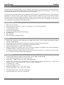
Introduction
Thank you for purchasing the Video Over IP Controller. This product has been designed to provide trouble free,
reliable operation. It benefits from both a LINDY 2 year warranty and free lifetime technical support. To ensure correct
use, please read this manual carefully and retain it for future reference.
This Video Over IP Controller enables the management and configuration of multiple Video over IP (VoIP) extenders
(No.38266 and 38267) through a single WebGUI, that provides the complete status of all connected transmitters
(No.38266) and receivers (No.38267), including IP address, channel selection and video preview. It also features
local console ports including an HDMI output and one USB port for the connection of a keyboard or mouse (or both
via a USB hub), to view and interact with the WebGUI.
Package Contents
▪ Video Over IP Controller
▪ Multi-country 5V DC 2.6A PSU, 5.5mm / 2.1mm with EU, UK, US and AUS adapters
▪ 1 x terminal block (3-pin)
▪ 3 x terminal block (5-pin)
▪ 3.5mm to IR extender cable
▪ Remote control (with included CR2025 battery)
▪ 4 x rubber feet
▪ OSS statement
▪ Lindy QIG (Quick Installation Guide)
Features
▪ Enables the management and configuration of multiple Video over IP (VoIP) extender (No.38266 and 38267)
through a single WebGUI
▪ Supports point-to-point (unicast) and multipoint-to-multipoint (multicast) routing selections
▪ Controls both Matrix and TV wall configurations using WebGUI presets
▪ Definable display groups to simplify large installations
▪ WebGUI provides the complete status of all connected transmitters (No.38266) and receivers (No.38267),
including IP address, channel selection and video preview.
▪ Local console featuring an HDMI output and one USB port for the connection of a keyboard or mouse (or both
via a USB hub), to view and interact with the WebGUI
Specifications
▪ Control modes: WebGUI (remote or local), RS-232, Telnet, Trigger and IR Remote
▪ RJ45 Gigabit Ethernet port with PoE support (802.3af)
▪ Output port: 1 x HDMI Female (resolution: 1920x1080@60Hz)
▪ Control ports: 1 x RS232 (3 pin terminal block), 8 x Trigger Contacts (10 pin terminal block), 1 x USB Type A
Female, 2 x RJ45, 1 x Factory Reserved Connector (5 pin terminal block)
▪ IR Frequency: 30 – 50kHz
▪ Power Consumption: 2.99 W
▪ Operating Temperature: 0°C - 40°C (32°F - 104°F)
▪ Storage Temperature: -20°C - 60°C (-4°F - 140°F)
▪ Operating Humidity: 20% - 90% (non-condensing)
▪ Storage Humidity: 20% - 90% (non-condensing)

User Manual English
2
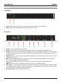
Overview
Front Panel
1. Power LED – Flashes during power up and stays illuminated whilst the unit is operating.
2. IR Eye – Receives the IR signal from the included IR remote control
Rear Panel
1. IR Ext - Connects to the provided IR extender to extend the IR control range of the unit.
2. Control – Socket reserved for factory updates
3. RS-232 – Serial socket to be connected with a serial controller or PC through the supplied terminal
4. Trigger IN: Connects any trigger device (not supplied) such as, control keypads, security alarms, door switches,
etc. Each of the 8 trigger inputs can be used to activate an associated preset. The trigger needs a minimum of
5V to be activated
5. HDMI OUT port – Connects a display with a standard HDMI cable (not included) used for direct local monitoring
/ management of the unit.
6. USB: Connects a USB mouse and/or keyboard to control the unit’s WebGUI displayed on the HDMI output
port. Firmware update via USB is also supported.
Note: Specialized USB control devices, such as a touch panel, should be connected before the unit is
powered on.
7. LAN 2 – Connect this port to the network used to control the unit via WebGUI / Telnet
8. LAN 1 (PoE) – This port must be connected to the network where all the controlled units (No. 38266 and 38267
– not included) are connected to. If this port is connected to an IEEE802.3af. compliant switch the unit can get
power directly from it avoiding to use the included PSU.
9. DC Power socket – Attach the supplied PSU here.

User Manual English
3
IR Extender
IR Receiver cable for the connection with the IR Ext port
Remote Control
The included remote control has 8 buttons that recall an associated
preset allowing the user to quickly change the screen layout.
Installation
Please follow the following steps to install the Video over IP Controller:
1. Please make sure that all the devices included in the installation are shut down
2. Connect, as required, the HDMI, USB (for keyboard and mouse or control devices only), Serial and Trigger
ports on the unit to the devices you want to attach to this system using standard cables.
3. Connect, as required, the IR extender cable to the IR EXT port
4. Connect a standard RJ45 Ethernet cable to the “LAN 2” port and to the network where the (No. 38266 and
38267) units are connected to. If you are connecting the units to a Gigabit PoE (IEEE 802.3af compliant) switch
you can skip step 6 and avoid using the supplied PSU.
5. Connect a standard RJ45 Ethernet cable to the “LAN 1 (PoE)” port to the network where the used control PC
to is connected to.
6. Connect (if required) the supplied PSU DC plug to the DC 5V ports
7. Turn on all the connected devices.
Now all the connections are made and the system is ready to be configured and distribute the managed signals.
Please refer to the full manual published on the product’s page (www.lindy.com) to proceed with a detailed
configuration.
Operation
Please refer to the following section to control the device through the integrated WebGUI or with RS232 serial
interface
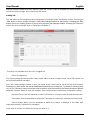
Device Discovery Tool
Please download the “Device Discovery” software from the Lindy website (you can find in the page
dedicated to this device) and save it in a directory where you can easily find it.
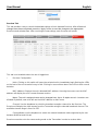
Connect the unit and your PC/laptop to the same active network and execute the “Device Discovery”
software. Click on “Find Devices on Network” and a list of devices connected to the local network will show
up indicating their current IP address.

User Manual English
4
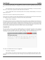
By clicking on one of the listed devices you will be presented with the network details of that particular
device.
IP Mode:
If you choose, you can alter the static IP network settings for the device, or switch the unit into DHCP
mode to automatically obtain proper network settings from a local DHCP server. To switch to DHCP mode,
please select DHCP from the IP mode drop-down, then click “Save” followed by “Reboot”.
WebGUI Hotkey:
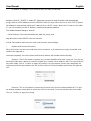
Once you are satisfied with the network settings, you may use them to connect via Telnet or WebGUI. The
network information window provides a convenient link to launch the “WebGUI” directly.
WebGUI CONTROL PAGE
All functions of this unit are controllable via the built in WebGUI which is accessed by connecting your web
browser to LAN 2’s IP address or by connecting an HDMI display to the unit’s HDMI output and attaching
a USB mouse and keyboard to the unit’s USB port. This control is presented across a number of separate
tabs, including Monitor & Control, Preset Recall, System, Setting, Transmitter, and Receiver.
A setup wizard is also provided to help simplify first-time setup. The individual functions will be introduced
in the following sections.
When no user is logged in, a limited selection of tabs are available (Monitor & Control, Preset Recall, and
System). This allows for easy user access to routing selection and presets while still protecting the more
sensitive and critical setup and configuration controls. To log in to the WebGUI, switch to the System tab
and click on the “Login” button.
By default, both the Username and Password are set to “admin” for the WebGUI. The administrator
password can be changed within the System tab of the WebGUI if desired.

User Manual English
5
If you are unsure of the unit’s current LAN 2 IP address, please check the unit’s HDMI status display.
Monitor & Control Tab
This tab provides a graphical representation of all current Transmitters, Receivers and video groups. It
also provides a simple way to change video routing by using drag and drop. The video thumbnails may be
set to automatically update every few seconds by clicking the "Auto Refresh" switch to the right.
NOTE: This tab is fully functional even when the user is logged out.
• Source Preview
This window displays preview thumbnails from all detected Transmitters along with their assigned names.
To route a Transmitter’s source to a different Receiver, or to a video group, drag-and-drop can be used.
Click and drag the thumbnail from the Source side to drop it onto the prefered Receiver or Display Group
on the Zone side.
• Zone Preview
This window displays preview thumbnails from all detected Receivers along with their assigned names. All
available Display Groups are also displayed here, however no preview thumbnail will be displayed for
them. Display Groups are defined within the Setting tab.
Due to the potential for the displays within a video group to be showing different sources, video groups will
not show a thumbnail image.

User Manual English
6
Preset Recall Tab
This tab lists all currently defined Presets and provides a simple way to activate them. To activate a saved
Preset, simply click on the appropriately named button. Presets are defined within the Setting tab.
This tab is fully functional even when the user is logged out.
System Tab
This tab provides access to system configuration options including IP configuration for both LAN ports,
login and user management, access to the setup wizard, and firmware update functionality.
This tab will only display system information and provide a Login button if the user is logged out. All other
functions will be greyed out.
• LAN1 & LAN2
The IP mode for each LAN port (DHCP, Static IP, or Auto IP), IP address, netmask, and gateway can be
set here. When a LAN port is set to Auto IP mode it will automatically assign itself an APIPA address from

User Manual English
7
the 169.254.XXX.XXX range. When a LAN port is set to “DHCP” mode, it will automatically attempt to
obtain proper configuration information from the local DHCP server. If no DHCP server is available, or the
user wishes to configure the network settings manually, please set the LAN port to “Static IP” mode and
enter the information as appropriate for the connected network. Press “Save” to activate the changes.
LAN1 defaults to "Auto IP" mode and is intended to be connected to the VoIP device network. LAN2
defaults to "DHCP" mode and is intended to be connected to a normal local network for easy access to
the WebGUI.
• Login & Logout
Click these buttons to log in or log out of the WebGUI interface. When logged out, available WebGUI
functionality is limited.
• Change Password
Click this button to change the WebGUI's administrator login password.
• Reset
Click this button to clear all detected transmitter/receiver information, all groups and all presets. LAN
settings will not be reset.
• Reboot
Click this button to reboot the unit.
• Wizard
Click this button to launch the setup wizard. Activating the wizard will clear all detected transmitter/receiver
information, all groups and all presets.
• Favicon
This allows for the upload of an icon image to use as the WebGUI's page/tab icon which is also commonly
used by browsers when a web page has been bookmarked or added to favorites. The image file must be
16×16 pixels and saved in the *.ico format. The file must be named "favicon.ico".
Click the “Choose File” button, select the file from your PC's file browser, then click the "Upload" button.
Once the upload is complete, refresh the WebGUI to view the new icon.
• Logo
This allows for the upload of a small logo image that will be displayed in the upper left corner of the
WebGUI. The image is recommended to be no taller than 90 pixels and must be saved in the *.png format.
The file must be named "logo.png".
Click the “Choose File” button, select the file from your PC's file browser, then click the "Upload" button.
Once the upload is complete, refresh the WebGUI to view the corner logo.

User Manual English
8
• Firmware Upgrade
It is possible to update the firmware of this unit as well as to update the firmware of detected Transmitters
(No.38266) and Receivers (No.38267). The number of currently detected Transmitters and Receivers is
also listed here.
To update the unit's firmware, or the firmware of detected Transmitters or Receivers, click the “Choose
File” button beneath the appropriate device type (IP Master Controller, Transmitter, or Receiver) to open
the file selection window and then select an appropriate firmware update file (*.bin format) located on your
local PC. After selecting the file, click the “Upgrade” button beneath the appropriate device type to begin
the firmware update process. Once the firmware update process has completed each updated unit will
reboot. The firmware update process can take several minutes, please do not power the units off once the
process has begun.
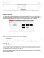
Setup Wizard
Pressing the “Wizard” button will start the step by step Setup Wizard.
It will also clear the unit’s stored Transmitter/Receiver history, Presets, and Groups. The following 4
windows will then be presented, in order, to simplify the initial setup of a new Video over IP routing
installation. Prior to pressing the “Finish” button on the final page of the wizard,it is possible to move freely
between all 4 steps of the Setup Wizard to make additional changes to the configuration. Once “Finish”
has been pressed, the changes will be committed to all involved units and they will reboot.
(1) Transmitter Setting
This wizard step provides a way to control the detailed settings
of each detected Transmitter. First, click on the “Scan” button to check the LAN 1 network for all available
Transmitters. Once the list is populated with Transmitters, the settings for each can be modified (See the
“Transmitter Tab” section for configuration details). After all desired changes have been completed, press
the “Next” button to move to the next wizard step.
(2) Receiver Setting
This wizard step provides a way to control the detailed settings of each detected Receiver. First, click on
the “Scan” button to check the LAN 1 network for all available Receivers. Once the list is populated with
Receivers, the settings for each can be modified (See the “Receiver Tab” section for configuration details).
After all desired changes have been completed, press the “Next” button to move to the next wizard step.
(3) Group Setting
This wizard step provides a way to define groups of displays that will all receive the same routed source
when used in Presets or from the Monitor & Control tab (See the “Display Group Configuration” section for
configuration details). After all desired Display Groups have been defined, press the “Next” button to move
to the next wizard step.
(4) Preset Setting
This wizard step provides a way to add, edit or remove routing Presets (See the “Preset Configuration”
section for configuration details).

User Manual English
9
After all desired Presets have been defined, press the “Finish” button to complete the Setup Wizard and
commit all setup changes. All involved units will reboot.
Setting Tab
This tab allows for the assignment and configuration of routing Presets and Display Groups. Pressing the
“Add” button in either section will open a new blank settings window for that section. Pressing the “Edit”
button next to an existing Preset or Group item will open that settings window. Pressing the “Remove”
button next to an existing Preset or Group item will delete it.
This tab is not available when the user is logged out.
• Preset Configuration
The Preset settings window provides a way to add, edit or remove routing Presets. Up to 250 Presets can
be easily defined and managed.
Once the Preset settings window is open, the name of the Preset can be set at the top of the window.
Pressing the “Add” button will add an additional Receiver/Group routing line. To delete an existing route,
click on the “Remove” button next to the route to remove. Once all routes for the Preset have been defined,
press the “Confirm” button to save the changes. Each route line has the following configurable settings:
- Receiver/Group: Use the dropdown to select a Receiver or Group to route the selected source to.
- Transmitter: Use the dropdown to select the Transmitter to route to the selected Receiver/Group.
- Vertical (Video Wall): Use the dropdown to define the number of displays in the video wall,
measured vertically. (Maximum is 8 displays.)
If this route is not part of a video wall, leave the value at 1.

User Manual English
10
- Horizontal (Video Wall): Use the dropdown to define the number of displays in the video wall,
measured horizontally. (Maximum is 8 displays.) If this route is not part of a video wall, leave the value at
1.
- Row (Video Wall): Set the vertical position of the currently selected display. (Counts top to bottom,
from 0 to 7.) If this route is not part of a video wall, leave the value at 0.
- Column (Video Wall): Set the horizontal position of the currently selected display. (Counts top to
bottom, from 0 to 7.)
If this route is not part of a video wall, leave the value at 0.
Please note: if you require to set up a Video Wall larger than 8 x 8 please refer to the Telnet control section.
The WebGUI interface is limited to 8 x 8 because of the video preview feature.
• Display Group Configuration
The Display Group device selection window provides a way to define a group of displays that will all receive
the same routed source when used in Presets or from the Monitor & Control tab. The name of the Display
Group is set at the top of the window. To add Receivers to the Display Group, click on the name of each
one to include. To remove a Receiver from the group, click on the Receiver’s name a second time. After
all selections have been made, click on the “Confirm” button to save the changes.
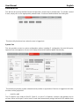
Transmitter Tab
This tab provides a way to control the detailed settings of each detected Transmitter. After all desired
changes have been completed, press the “Apply” button to send the changes to the appropriate
Transmitters and activate them. After receiving the new settings, each Transmitter will reboot.
This tab is not available when the user is logged out.
• Transmitter Configuration
- Hello: Clicking on this switch will cause the selected unit to immediately begin flashing the LEDs
on the front of the unit to make it easy to find. Clicking it a second time returns the LEDs to their normal
behavior.

User Manual English
11
- MAC Address: Displays the unit's detected MAC address. Hovering the mouse over the MAC
address will display the unit's current firmware revision.
- Name: The unit’s assigned name can be changed here. Up to 12 alpha-numeric characters are
allowed. By default, new units will use their MAC address as their name.
- Channel: Use the dropdown to select the broadcast channel for the Transmitter. All Receivers on
the local network that are set to the same channel will receive video from this Transmitter. The available
channel range is from 0 to 255. Every Transmitter within the same local network must be assigned a
different broadcast channel in order to avoid conflicts.
- Casting Mode: Use the dropdown to switch the broadcasting mode used by the unit between Multicast
and Unicast.
Receivers must be set to the same casting mode as the Transmitter in order to receive video.
- IP Mode & IP Settings: The IP mode of each unit may be switched between “Auto IP”, “DHCP” or
“Static IP”. When the unit is set to Auto IP mode it will automatically assign itself an APIPA address from
the 169.254.XXX.XXX range. When the unit is set to DHCP mode it will attempt to automatically obtain
an IP address from a DHCP server. When the IP mode is set to static IP, you can manually set the IP
address, netmask and gateway address.
The default network setting is “Auto IP”.
- Serial Settings: Set the desired baud rate, data bits, parity, and stop bits for the unit’s RS-232
extension function. Linked Transmitters and Receivers must have the same serial settings.
• Replace and Remove Transmitters
When a Transmitter has been removed from the local network, or is otherwise no longer accessible, and
needs to be replaced, or removed completely, then the Replace and Remove buttons will provide that
functionality.
- Replace: Click on this button to replace any currently listed Transmitter with a new unit. The pop-
up window provides drop- downs to select the original unit, and the unit to replace it with. Once the
selection has been made, click on "Confirm" to apply the change. Once the replace process has
completed, the replaced unit will be removed from the list, and the new unit will have settings copied
from the replaced unit.
- Remove: Click on this button to remove any Transmitter from the list of detected devices. The
pop-up window provides a drop- down to select the unit to be removed. Once the selection has been
made, click on "Confirm" to apply the change.

User Manual English
12
Receiver Tab
This tab provides a way to control the detailed settings of each detected Receiver. After all desired
changes have been completed, press the “Apply” button to send the changes to the appropriate
Receivers and activate them. After receiving the new settings, each Receiver will reboot.
This tab is not available when the user is logged out.
• Receiver Configuration
- Hello: Clicking on this switch will cause the selected unit to immediately begin flashing the LEDs
on the front of the unit to make it easy to find. Clicking it a second time returns the LEDs to their normal
behavior.
- MAC Address: Displays the unit's detected MAC address. Hovering the mouse over the MAC
address will display the unit's current firmware revision.
- Name: The unit’s assigned name can be changed here. Up to 12 alpha-numeric characters are
allowed. By default, new units will use their MAC address as their name.
- Channel: Use the dropdown to select the broadcast reception channel for the Receiver. The
Receiver will display the video stream from the Transmitter using the selected broadcast channel. The
available channel range is from 0 to 255.
- Casting Mode: Use the dropdown to switch the network broadcast mode supported by the unit
between Multicast and Unicast.
Receivers must be set to the same casting mode as the Transmitter in order to receive video.

User Manual English
13
- IP Mode & IP Settings: The IP mode of each unit may be switched
between “Auto IP”, “DHCP” or “Static IP”. When the unit is set to Auto IP mode it will automatically
assign itself an APIPA address from the 169.254.XXX.XXX range. When the unit is set to DHCP mode it
will attempt to automatically obtain an IP address from a DHCP server. When the IP mode is set to static
IP, you can manually set the IP address, netmask and gateway address.
The default network setting is “Auto IP”.
- Serial Settings: Set the desired baud rate, data bits, parity, and
stop bits for the unit’s RS-232 extension function.
Linked Transmitters and Receivers must have the same serial settings.
• Replace and Remove Receivers
When a Receiver has been removed from the local network, or is otherwise no longer accessible, and
needs to be replaced, or
removed completely, then the Replace and Remove buttons will provide that functionality.
- Replace: Click on this button to replace any currently listed Receiver with a new unit. The pop-up
window provides drop- downs to select the original unit, and the unit to replace it with. Once the selection
has been made, click on "Confirm" to apply the change. Once the replace process has completed, the
replaced unit will be removed from the list, and the new unit will have settings copied from the replaced
unit.
- Remove: Click on this button to remove any Receiver from the list of detected devices. The pop-
up window provides a drop-down to select the unit to be removed. Once the selection has been made,
click on "Confirm" to apply the change.

User Manual English
14
TELNET CONTROL
Please refer to the following Telnet command list to setup your configuration through an IP or Serial RS-
232 connection. Before attempting to use Telnet control, please ensure that both the unit’s LAN 2 port and
the PC/laptop are connected to the same active networks.
Note 1: By default the unit will obtain the LAN 2 IP address via DHCP. If you are unsure of the unit’s current
LAN 2 IP address, please check the unit’s HDMI status display.
Note 2: Commands will not be executed unless followed by a carriage return. Commands are not case-
sensitive.
Note 3: If the unit's IP address is changed then the IP address required for Telnet access will also change
accordingly.
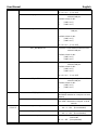
RS-232 and Telnet Commands
COMMAND
CLASS
COMMAND SINTAX
DESCRIPTION
SYSTEM
COMMANDS
HELP
Show the full command list.
GET_HARDWARE_VERSION
Show the unit’s hardware version.
GET_FIRMWARE_VERSION
Show the unit’s current firmware version.
SET_FACTORY_RESET
Reset the unit to the factory defaults.
SET_HISTORY_RESET
Clear the unit’s stored transmitter and
receiver history list.
REBOOT
Reboot the unit.
NETWORK
GET_IPCONFIG N1
Show the current Ethernet
configuration of the selected port.
Available values for N1:
1 [LAN Port 1]
2 [LAN Port 2]
SET_IP_MODE N1 N2
Set the IP configuration mode.
Available values for N1:
1 [LAN Port 1]
2 [LAN Port 2]
Available values for N2:
0 [Static IP Mode]
1 [DHCP Mode]
2 [Auto IP Mode]
GET_IP_MODE N1
Show the current IP configuration mode.
Available values for N1:
1 [LAN Port 1]
2 [LAN Port 2]
SET_IP_ADDRESS N1 N2
Set the static IP address for the selected
LAN port
Available values for N1:
1 [LAN Port 1]
2 [LAN Port 2]

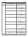
User Manual English
15
N2 = X.X.X.X [X = 0~255]
GET_IP_ADDRESS N1
Show the current IP address of the
selected LAN port
Available values for N1:
1 [LAN Port 1]
2 [LAN Port 2]
SET_NETMASK N1 N2
Set the Ethernet netmask for the selected
LAN port
Available values for N1:
1 [LAN Port 1]
2 [LAN Port 2]
N2 = X.X.X.X [X = 0~255]
GET_NETMASK N1
Show the current Ethernet netmask of the
selected LAN port
Available values for N1:
1 [LAN Port 1]
2 [LAN Port 2]
SET_GATEWAY N1 N2
Set the IP gateway address for the
selected LAN port
Available values for N1:
1 [LAN Port 1]
2 [LAN Port 2]
N2 = X.X.X.X [X = 0~255]
GET_GATEWAY N1
Show the current gateway address of the
selected LAN port
Available values for N1:
1 [LAN Port 1]
2 [LAN Port 2]
DISCOVERY
GET_TX_DEVICE
List all supported VoIP Transmitter devices
(No.38266) detected on LAN port 1’s local
network.
GET_RX_DEVICE
List all supported VoIP Receiver devices
(No.38267) detected on LAN port 1’s local
network.
PRESET
/ GROUP
SET_PRESET_RUN N1
Activate Preset number N1
N1 = 1 ~ 250 [Preset Number]
GET_PRESET_RUN N1
List the contents of Preset number N1
N1 = 1 ~ 250 [Preset Number]
SET_GROUP_ROUTE N1 N2
Set all members of Group N1 to display
Channel N2
N1 = 1 ~ 255 [Group Number]

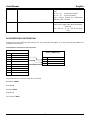
User Manual English
16
N2 = 0 ~ 255 [Channel Number]
GET_GROUP_MEMBER N1
List all Receivers in Group N1
N1 = 1 ~ 255 [Group Number]
INDIVIDUAL
VoIP UNIT
SET_CHANNEL N1 N2
Set the Channel for the Tx or Rx at IP
address N1.
N1 = X.X.X.X [X = 0 ~ 255, IP of Target
Unit]
N2 = 0 ~ 255 [Channel Number]
GET_CHANNEL N1
Show the current Channel used by the Tx
or Rx at IP address N1.
N1 = X.X.X.X [X = 0 ~ 255, IP of Target
Unit]
SET_DEVICE_NAME N1 N2
Set the name of the Tx or Rx at IP address
N1.
N1 = X.X.X.X [X = 0 ~ 255, IP of Target
Unit]
N2 = {Name} [Alpha-numeric, 12 Chars
Max]
GET_DEVICE_NAME N1
Show the current name of the Tx or Rx at
IP address N1.
N1 = X.X.X.X [X = 0 ~ 255, IP of Target
Unit]
SET_NET_MODE N1 N2
Set the network broadcast mode of the Tx
or Rx at IP address N1.
N1 = X.X.X.X [X = 0 ~ 255, IP of Target
Unit]
Available values for N2:
0 [Unicast Mode]
1 [Multicast Mode]
GET_NET_MODE N1
Show the current network broadcast mode
of the Tx or Rx at IP address N1.
N1 = X.X.X.X [X = 0 ~ 255, IP of Target
Unit]
SET_VW_LAYOUT N1 N2 N3
Set the horizontal and vertical display count
of the video wall that the Rx at IP address
N1 is a part of.
N1 = X.X.X.X [X = 0 ~ 255, IP of Target
Unit]
N2 = 1 ~ 16 [Horizontal Display Count]
N3 = 1 ~ 16 [Vertical Display Count]
GET_VW_LAYOUT N1
Show the horizontal and vertical display
count of the video wall that the Rx at IP
address N1 is a part of.
N1 = X.X.X.X [X = 0 ~ 255, IP of Target
Unit]
SET_VW_POS N1 N2 N3
Set the horizontal and vertical position of
the Rx at IP address N1 within the defined
video wall.

User Manual English
17
N1 = X.X.X.X [X = 0 ~ 255, IP of Target
Unit]
N2 = 0 ~ 15 [Horizontal Position]
N3 = 0 ~ 15 [Vertical Position]
Note: Cannot exceed the dimensions
defined by VW_LAYOUT
GET_VW_POS N1
Show the horizontal and vertical position of
the Rx at IP address N1 within the defined
video wall.
N1 = X.X.X.X [X = 0 ~ 255, IP of Target
Unit]
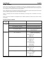
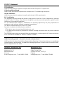
RS232 INTERFACE DESCRIPTION
Please refer to the following serial ports pin out and connection description to connect correctly the interface to
standard RS232 devices.
Serial interface pin functions and connections
PC SERIAL DB9 PORT
Pin
Function
1
NC
2
Rx
3
Tx
4
NC
5
GND
6
NC
7
NC
8
NC
9
NC
The serial interface on the PC must be set as follow:
Baud Rate: 19200
Data Bits: 8
Parity Bit: None
Stop Bits: 1
Flow Control: None
VIDEO OVER IP CONTROLLER
SERIAL CONNECTOR
Pin
Function
1
Tx
2
Rx
3
GND
La pagina si sta caricando...
La pagina si sta caricando...
-
 1
1
-
 2
2
-
 3
3
-
 4
4
-
 5
5
-
 6
6
-
 7
7
-
 8
8
-
 9
9
-
 10
10
-
 11
11
-
 12
12
-
 13
13
-
 14
14
-
 15
15
-
 16
16
-
 17
17
-
 18
18
-
 19
19
-
 20
20
-
 21
21
-
 22
22


Lindy 38263 Manuale utente
- Categoria
- Server / codificatori video
- Tipo
- Manuale utente
in altre lingue
- English: Lindy 38263 User manual
- français: Lindy 38263 Manuel utilisateur
