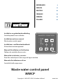
Vetus WWCP Waste Water Control Panel Manuale utente
- Tipo
- Manuale utente

vetus
WASTE CONTROL
100%
50%
75%
25%
Copyright © 2022 VETUS B.V. Schiedam Holland 090427.02
Installatie- en gebruikershandleiding
Controlepaneel voor vuilwater
Installation and user manual
Waste water control panel
Installations- und Benutzerhandbuch
Schmutzwasser management
Manuel d’Installation et d’utilisation
Tableau de contrôle d’eaux usées
Manual de instalación y usuario
Panel de control para la descarga del agua sanitaria
Manuale d’installazione e d’uso
Controllo livello acque nere
Waste water control panel
NEDERLANDS
4
ENGLISH
12
DEUTSCH
20
FRANÇAIS
28
ESPAÑOL
36
ITALIANO
44
WWCP

2 090427.02 Waste water control panel WWCP

090427.02 3
Waste water control panel WWCP
1 Inleiding . . . . . . . . . . . . . . . . . . . . . . . . . . . . . 4
2 Bediening. . . . . . . . . . . . . . . . . . . . . . . . . . . . 5
3 Installatie . . . . . . . . . . . . . . . . . . . . . . . . . . . . 7
4 Instelprocedure . . . . . . . . . . . . . . . . . . . . . . 8
5 Technische gegevens . . . . . . . . . . . . . . . . 10
1 Introduction . . . . . . . . . . . . . . . . . . . . . . . . 28
2 Commande
. . . . . . . . . . . . . . . . . . . . . . . . . 29
3 Installation. . . . . . . . . . . . . . . . . . . . . . . . . . 31
4 Procédure de réglage. . . . . . . . . . . . . . . . 32
5 Fiche technique . . . . . . . . . . . . . . . . . . . . . 34
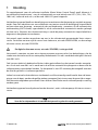
Inhoud
Sommaire
1 Introduction . . . . . . . . . . . . . . . . . . . . . . . . 12
2 Operating instructions . . . . . . . . . . . . . . 13
3 Installation. . . . . . . . . . . . . . . . . . . . . . . . . . 15
4 Set-up procedure. . . . . . . . . . . . . . . . . . . . 16
5 Technical specications. . . . . . . . . . . . . . 18
1 Einleitung. . . . . . . . . . . . . . . . . . . . . . . . . . . 20
2 Bedienung . . . . . . . . . . . . . . . . . . . . . . . . . . 21
3 Installation. . . . . . . . . . . . . . . . . . . . . . . . . . 23
4 Einstellverfahren . . . . . . . . . . . . . . . . . . . . 24
5 Technische Daten . . . . . . . . . . . . . . . . . . . 26
1 Introducción . . . . . . . . . . . . . . . . . . . . . . . . 36
2 Instrucciones de uso. . . . . . . . . . . . . . . . . 37
3 Instalación . . . . . . . . . . . . . . . . . . . . . . . . . . 39
4 Procedimiento de conguración . . . . . 40
5 Especicaciones técnicas . . . . . . . . . . . . 42
1 Introduzione . . . . . . . . . . . . . . . . . . . . . . . . 44
2 Funzionamento . . . . . . . . . . . . . . . . . . . . . 45
3 Installazione . . . . . . . . . . . . . . . . . . . . . . . . 47
4 Impostazione
. . . . . . . . . . . . . . . . . . . . . . . 48
5 Caratteristiche tecniche . . . . . . . . . . . . . 50
Content
Inhalt
Índice Indice
6 Aansluitschema’s . . . . . . . . . . . . . . . . . . . . 52
7 Hoofdafmetingen . . . . . . . . . . . . . . . . . . . 55
6 Anschlußschaltplane . . . . . . . . . . . . . . . . 52
7 Hauptabmessungen. . . . . . . . . . . . . . . . . 55
6 Esquemas de conexión . . . . . . . . . . . . . . 52
7 Dimensiones principales. . . . . . . . . . . . . 55
6 Wiring diagrams. . . . . . . . . . . . . . . . . . . . . 52
7 Principal dimensions . . . . . . . . . . . . . . . . 55
6 Schémas électrique. . . . . . . . . . . . . . . . . . 52
7 Dimensions principales. . . . . . . . . . . . . . 55
6 Schemi dei collegamenti. . . . . . . . . . . . . 52
7 Dimensioni principali. . . . . . . . . . . . . . . . 55

4 090427.02 Waste water control panel WWCP
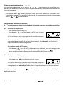
1 Inleiding
Dit controlepaneel voor de vuilwater-installatie (Waste Water Control Panel) geeft allereerst 4
verschillende inhoudsniveau`s van de vuilwatertank aan met behulp van LED`s (25%, 50%, 75%,
100% vol). Indien de tank vol is, zal de rode 100% LED gaan knipperen.
Het bedieningspaneel heeft een beveiliging om te voorkomen dat de pomp per ongeluk aangezet
wordt. Door het indrukken van een combinatie van toetsen wordt de beveiliging uitgeschakeld
en hierna kan men de pomp - automatisch dan wel handmatig - aanzetten. Als de automatische
tankbewaking (AUTO-mode) ingeschakeld is zal de vuilwatertank automatisch worden geleegd
als deze vol is. Wanneer de vuilwatertank leeg is wordt de pomp automatisch uitgeschakeld om
ongewenst drooglopen te voorkomen.
Het paneel moet worden aangesloten op een in de vuilwatertank gemonteerde Vetus niveau-
sensor. Geschikte sensoren zijn de sensor met vlotterarm, art.code: WWSENSORA, en de analoge
ultrasone sensor, art.code: SENSORA.
De digitale ultrasone sensor, art.code: SENSORB, is niet geschikt!
Het paneel is voorzien van een extra uitgang waarmee men een relais kan bekrachtigen, dat de
stroom naar het toilet en/of een waterpomp onderbreekt. Dit relais wordt bekrachtigd als de tank
voor 90% vol is.
Ook kan een elektrisch bediende afsluiter, indien geïnstalleerd, op het paneel worden aangeslo-
ten. Als de tank voor 90% vol is wordt eerst de afsluiter automatisch opengezet en daarna zal de
vuilwaterpomp ingeschakeld worden. Op het paneel is een LED aanwezig dat aangeeft wanneer
de afsluiter gesloten is (indien aangesloten).
Indien het maximale vloeistofniveau incidenteel en/of kortstondig wordt bereikt door de bewe-
gingen van de boot, worden dergelijke pieken genegeerd; het niveau moet langere tijd en onge-
acht de omstandigheden op maximaal staan alvorens de afsluiter en de vuilwaterpomp in werking
worden gezet.
Het bedieningspaneel wordt geleverd zonder de extra’s, zoals vuilwaterpomp, afsluiter en niveau-
sensor.
Let op
Voer de ‘Instelprocedure’ uit voordat het paneel in gebruik wordt genomen!
NEDERLANDS

090427.02 5
Waste water control panel WWCP
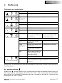
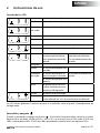
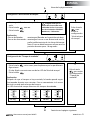
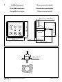
2 Bediening
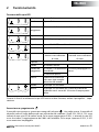
Functie van de LED’s
Uit: het paneel is uitgeschakeld.
Groen: het paneel is ingeschakeld.
Groen
knipperend:
de accuspanning is lager dan 8 Volt.
Uit: -
Groen: de pompcyclus is handmatig geactiveerd.
Uit: de auto-mode is niet ingeschakeld.
Groen: de auto-mode is ingeschakeld.
Elektrisch be-
diende afsluiter met
standterugmelding
Handbediende
afsluiter zonder
standterugmelding
Uit: -
Groen: de afsluiter is gesloten. -
Groen knip-
perend:
de afsluiter is aan het
openen of aan het
sluiten.
de pompcyclus is actief.
de afsluiter is geopend.
Rood: het openen of sluiten is
niet binnen 40 seconden
gelukt.
-
Groen: de pomp is ingeschakeld.
Rood: de pomp is ingeschakeld maar het niveau in de tank
is niet binnen de gestelde tijd 10% gedaald.
Tijdens het instellen hebben de Led’s een andere functie; zie 4 Instelprocedure.
In- of uitschakelen
Met de toets wordt het paneel in- of uitgeschakeld. Na het inschakelen wordt het niveau in
de vuilwatertank aangegeven. De niveaus 25%, 50% en 75% worden met een groene LED aange-
geven. Bij 90% gaat de rode 100% LED aan. Bij meer dan 95% gaat de rode 100% LED knipperen.
NEDERLANDS

6 090427.02 Waste water control panel WWCP
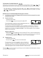
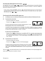
Vrijgeven toetsvergrendeling
Om ongewenste bediening van de toetsen en te voorkomen is een beveiliging inge-
bouwd. Deze beveiliging moet eerst worden uitgeschakeld alvorens de pompfunctie kan worden
ingesteld of gebruikt.
• Druk hiertoe beide toetsen gelijktijdig in en houdt deze gedurende 5 seconden inge-
drukt. Na de pieptoon is de beveiliging gedurende 10 seconden uitgeschakeld en kunnen de
toetsen en worden bediend.
Leegpompen van de vuilwatertank
A - Installatie met een elektrisch bediende afsluiter welke voorzien van standterugmelding:
A1 - Automatisch leegpompen
• Geef de toetsvergrendeling vrij.
• Druk de toets in om het paneel in AUTO-mode te zetten.
Als het niveau in de tank is gestegen tot 95% wordt de pompcy-
clus automatisch geactiveerd.
Eerst wordt de afsluiter is geopend daarna wordt de pomp ingeschakeld. De pomp blijft
nog enige tijd ingeschakeld als de tank is leeggepompt, zie nadraaitijd. Als de pomp is
uitgeschakeld wordt de afsluiter gesloten.
Uitschakelen van de AUTO-mode:
• Druk de toets in om de AUTO-mode weer uit te schakelen, het is niet nodig eerst de
toetsvergrendeling vrij te geven. Als tijdens het leegpompen de toets wordt inge-
drukt wordt de automatische pompcyclus beëindigd en de afsluiter gesloten.
A2 - Niet-automatisch leegpompen
• Geef de toetsvergrendeling vrij.
• Druk op de toets om de pompcyclus te starten.
Eerst wordt de afsluiter is geopend daarna wordt de pomp inge-
schakeld. De pomp blijft nog enige tijd ingeschakeld als de tank
is leeggepompt, zie nadraaitijd. Als de pomp is uitgeschakeld wordt de afsluiter gesloten.
Als tijdens het leegpompen de toets wordt ingedrukt wordt de pompcyclus beëindigd en
de afsluiter gesloten.

090427.02 7
Waste water control panel WWCP
B - Installatie met een handbediende afsluiter welke niet voorzien van standterugmelding:
• Geef de toetsvergrendeling vrij.
• Open de afsluiter.
• Druk op de toets om de pompcyclus te starten.
Let op
De pomp wordt pas ingeschakeld na 40 seconden.
Binnen deze tijd kan alsnog de afsluiter worden open
gezet!
De pomp blijft nog enige tijd ingeschakeld als de tank is leeggepompt, zie nadraaitijd.
• Sluit de afsluiter als de pomp is uitgeschakeld.
WaarschuWing
Omdat de afsluiter niet is voorzien van een standterugmelding is zeer belangrijk om goed te
controleren of de afsluiter open staat voordat de tank wordt leeggepompt!
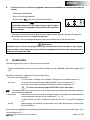
3 Installatie
Voor hoofdafmetingen zie pagina 55.
• Sluit het paneel aan zoals in de schema’s is aangegeven; zie pag. 52 - 54.
Op de 8-polige connector moet worden aangesloten:
- de voedingsspanning; 12 of 24 Volt, neem in de plus (+) draad een zekering van 10 A op.
- de sensor; een sensor met vlotterarm (WWSENSORA) volgens schema 7-1,
een analoge ultrasone sensor (SENSORA) volgens schema 7-2.
De digitale ultrasone sensor (SENSORB) is niet geschikt!
Het verdient aanbeveling om de sensor pas na het uitvoeren van de instelprocedure in de
tank te monteren.
- de pomp; een pomp die een stroomverbruik heeft van minder dan 10 A kan direct
op het paneel worden aangesloten; zie schema 7-1 en 7-2,
bij een pomp met een stroomverbruik van meer dan 10 A moet een
relais worden toegepast; zie schema 7-3.
- het relais; als de tank vol is kan hiermee een toilet worden uitgeschakeld en/of een
waarschuwingslamp worden ingeschakeld.
Op de 5-polige connector kan een elektrische bediende afsluiter worden aangesloten; zie
schema7-4.
NEDERLANDS

8 090427.02 Waste water control panel WWCP
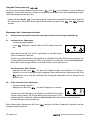
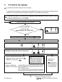
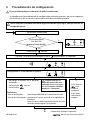
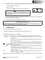
• Schakel de spanning in.
Is de LED ‘AAN’ aan?
Negeer alle andere LEDs.
• Druk eenmaal op de toets
• Druk de toets in en houdt deze gedurende ca. 10 seconden ingedrukt.
• Houdt de vlotter in de stand VOL.
• Druk eenmaal op de toets .
• Druk op de toets .
Toelichting:
- Vlottersensor: houdt de vlotter in de hoogste stand.
- Ultrasone sensor: houdt de sensor op korte afstand van een reec-
terend oppervlak.
N.B. De sensor moet gedurende ca. 10 seconden
stabiel in deze stand worden gehouden.
OF
• Druk op de
toets om
het instellen van
het ‘Maximale
tankniveau’ over
te slaan.
Instellen van het ‘Maximale tankniveau’.
JA
NEE
4 Instelprocedure
Na het aansluiten van het paneel moet deze worden ingesteld.
De instelprocedure wordt automatisch verlaten als er een minuut lang geen toets is inge-
drukt, of door op de aan/uit toets te drukken.
Altijd hier beginnen met het volgen van de instelprocedure ook indien slechts een en-
kele instelling gewijzigd moet worden!
AGa verder op de volgende pagina.
Zorg er voor dat
een ultrasone sensor
gekalibreerd is; zie ‘Instal-
latieinstructies SENSORA’
090429.01, ‘Kalibreren’.

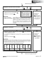
090427.02 9
Waste water control panel WWCP
OF
• Druk op de
toets om
het instellen van
het ‘Minimale
tankniveau’ over
te slaan.
Instellen van het ‘Minimale tankniveau’.
• Houdt de vlotter in de stand LEEG.
• Druk eenmaal op de toets .
• Druk op de toets .
Toelichting:
- Vlottersensor: houdt de vlotter in de laagste stand.
- Ultrasone sensor: houdt de sensor op een afstand van een reecte-
rend oppervlak gelijk aan de hoogte van de tank.
N.B. De sensor moet gedurende ca. 10 seconden
stabiel in deze stand worden gehouden.
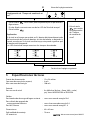
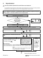
Instellen van de ‘Nadraaitijd’.
• Druk herhaaldelijk op de toets om door de mogelijke instel-
lingen te stappen.
De ingestelde waarde wordt door een van de LED ‘s ‘Tankniveau’
aangegeven.
• Druk op de toets .
Toelichting:
Nadat de tank leeggepompt is kan de pomp nog een aantal minuten
nadraaien. Dit is wenselijk als de niveausensor niet over het gehele
tankbereik meet.
De LED’s van de tankniveau-aanwijzing geven de tijd aan:
100%
50%
75%
25%
100%
50%
75%
25%
100%
50%
75%
25%
100%
50%
75%
25%
100%
50%
75%
25%
30 s 5 min 10 min 20 min 30 min
OF
• Druk op de
toets om
het instellen van
de ‘Nadraaitijd’
over te slaan.
A
BGa verder op de volgende pagina.
Vervolg van vorige pagina.
Zorg er voor dat
een ultrasone sensor
gekalibreerd is; zie ‘Instal-
latieinstructies SENSORA’
090429.01, ‘Kalibreren’.
NEDERLANDS

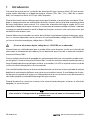
10 090427.02 Waste water control panel WWCP
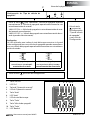
Instellen van de ‘Niveauveranderingstijd’.
• Druk herhaaldelijk op de toets om door de mogelijke instel-
lingen te stappen.
De ingestelde waarde wordt door een van de LED ‘s ‘Tankniveau’
aangegeven.
• Druk op de toets .
Toelichting:
Als het niveau in de tank niet binnen bepaalde tijd met 2% na het ac-
tiveren van de pompcyclus daalt wordt de pompcyclus afgebroken en
zal er een alarm klinken. Als het niveau niet daalt kan dit betekenen
dat de pomp verstopt is.
De LED’s van de tankniveau-aanwijzing geven de tijd aan:
100%
50%
75%
25%
100%
50%
75%
25%
100%
50%
75%
25%
2,5 min 5 min 10 min
OF
• Druk op de toets
om het
instellen van de
‘Niveauverande-
ringstijd’ over te
slaan.
BVervolg van vorige pagina.
CGa verder op de volgende pagina.
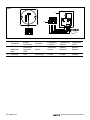
5 Technische gegevens
Aansluitspanning : 12/24 Volt
Stroomverbruik (stand-by) : 4 mA
Stroomverbruik max. : 100 mA
Ingang:
Voor niveausensor : 0 - 300 ohm (0 ohm = vol, 300 leeg)
bijv. Vetus WWSENSORA of SENSORA
Uitgangen:
Voor vuilwaterpomp : stroomverbruik max. 10 A
Voor elektrische bediende afsluiter : stroomverbruik max. 5 A
Voor WC / Alarm : stroomverbruik max. 1 A
Afmetingen : 85 x 85 mm
Inbouwdiepte : 78 mm

090427.02 11
Waste water control panel WWCP
• Druk op de toets om het instellen te beëindigen.
Instellen van het ‘Type afsluiter’.
• Druk op de toets om handbediende afsluiter of elektrisch
bediende afsluiter met standterugmelding te kiezen.
- LED 100% AAN: => Afsluiter zonder standterugmelding (handbe-
diend).
- LED 100% UIT: => Afsluiter met standterugmelding (elektrisch be-
diend).
Toelichting:
De LED’s van de tankniveau-aanwijzing geven aan of het paneel is
ingesteld voor een handbediende afsluiter of voor een elektrisch be-
diende afsluiter met standterugmelding:
100%
50%
75%
25%
100%
50%
75%
25%
handbediende afsluiter
zonderstandterugmelding
elektrisch bediende afsluiter
met standterugmelding
OF
• Druk op de toets
om het
instellen van het
‘Type afsluiter’
over te slaan en
het instellen te
beëindigen.
CVervolg van vorige pagina.
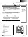
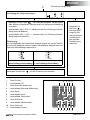
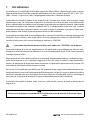
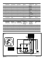
vetus
WASTE CONTROL
100%
50%
75%
25%
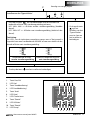
1 2 3 4 5 6
7 8 9 10 11
1. Toets ‘Aan/Uit’
2. LED ‘Aan’
3. Toets ‘Handbediening’
4. LED ‘Handbediening’
5. Toets ’Auto’
6. LED ‘Auto’
7. LED’s Tankniveau
8. Toets ‘Sleutel’
9. LED ‘Afsluiter’
10. Toets ‘Sleutel’
11. LED ‘Pomp’
NEDERLANDS

12 090427.02 Waste water control panel WWCP
1 Introduction
This control panel for the Waste Water installation uses LEDs to show four dierent levels in the
waste water tank (25%, 50%, 75%, and 100% full). If the tank is full, the red 100% LED will ash.
The control panel has a lock to prevent the pump from being switched on by accident. The lock is
switched o by pressing a combination of keys, after which the pump can be switched on either
automatically or manually. If automatic tank monitoring (AUTO mode) is switched on, the waste
water tank will empty automatically when it is full. The pump will switch o automatically when
the waste water tank is empty to prevent it continuing to run when dry.
The panel must be connected to a Vetus level sensor tted in the waste water tank. Suitable sen-
sors are sensors with a oat arm, art. code: WWSENSORA, and the analogue ultrasonic sensor, art.
code: SENSORA.
The digital ultrasonic sensor, art. code: SENSORD, is not suitable!
The panel has an extra output which can be used to power a relay used to interrupt the power to
the toilet and/or a water pump. This relay is powered when the tank is 90% full.
If an electrically operated shut-o valve is installed, this can also be connected to the panel. When
the tank is 90% full, the valve will rst be opened automatically and then the waste water pump
will be switched on. A LED on the panel shows when the shut-o valve is closed (if this is con-
nected).
If the maximum liquid level is reached incidentally and/or for a short period due to the movements
of the boat, such peaks will be ignored. The level must be at maximum for a longer period and ir-
respective of the circumstances before the shut-o valve and the waste water pump are engaged.
The control panel is supplied without the extras, such as the waste water pump, shut-o valve and
level sensor.
note
Carry out the ‘Set up procedure’ before bringing the panel into use!
ENGLISH

090427.02 13
Waste water control panel WWCP
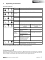
2 Operating instructions
Function of the LEDs
O: the panel is switched o.
Green: the panel is switched on.
Green
ashing:
the battery voltage is less than 8 Volts.
O: -
Green: the pump cycle is set to manual operation
O: the auto mode is not switched on.
Green: the auto mode is switched on.
Electrically operated
shut-o valve with status
feedback
Manually operated shut-
o valve without status
feedback
O: -
Green: the shut-o valve is
closed.
-
Green
ashing:
the shut-o valve is either
opening or closing.
the pump cycle is active.
the shut-o valve is
opened.
Red: opening or closing has
not been successful
within 40 seconds.
-
Green: the pump is switched on.
Red: the pump is switched on but the level in the tank has
not dropped by 10% within the set time.
The LEDs have dierent functions during set up; see 4 Set-up procedure.
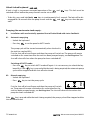
Switching on or o
The panel is switched on or o by using the key . The level in the waste water tank is indicated
after switching on. Levels 25%, 50% and 75% are shown with a green LED. The red 100% LED will
come on at 90%. The red 100% LED will ash when the level is higher than 95%.
ENGLISH

14 090427.02 Waste water control panel WWCP
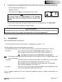
Unlock locked keyboard
A lock is built in to prevent unwanted operation of the and keys. This lock must be
switched o rst before the pump function can be set or used.
• To do this, press and hold both keys in simultaneously for 5 seconds. The lock will be dis-
engaged for 10 seconds after the peep sounds and the and keys can then be oper-
ated.
Pumping the waste water tank empty:
A - Installation with an electrically operated shut-o valve tted with status feedback:
A1 - Automatic emptying
• Unlock the keyboard.
• Press key to set the panel to AUTO mode.
The pump cycle will be started automatically when the level in
the tank has reached 95%.
First the shut-o valve will open and then the pump will switch on. The pump will remain
switched on for some time after the tank has been pumped empty, see nishing time. The
shut-o valve will close when the pump has been switched o.
Switching o AUTO mode:
• Press the key to switch AUTO mode o again. It is not necessary to unlock the key-
board rst. If the key is pressed while the tank is being emptied, the automatic pump
cycle will be stopped and the shut-o valve closed.
A2 - Manual emptying
• Unlock the keyboard.
• Press key to start the pump cycle.
First the shut-o valve will open and then the pump will switch
on. The pump will remain switched on for some time after the
tank has been pumped empty, see nishing time. The shut-o valve will close when the
pump has been switched o.
If the key is pressed while the tank is being emptied, the pump cycle will be stopped and the
shut-o valve closed.

090427.02 15
Waste water control panel WWCP
B - Installation with a manually operated shut-o valve without status feedback:
• Unlock the keyboard.
• Open the shut-o valve.
• Press the key to start the pump cycle.
note
The pump will begin to work after 40 seconds have
passed. The shut-o valve can still be opened during this
time!
The pump will remain switched on for some time after the tank has been pumped empty,
see nishing time.
• Close the shut-o valve after the pump has been switched o.
Warning
Because the shut-o valve does not have status feedback, it is very important to properly
check that the shut-o valve is open before starting to pump the tank empty!
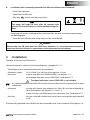
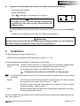
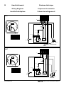
3 Installation
See page 55 for the main dimensions.
Connect the panel as shown in the wiring diagrams, see pages 52 - 54.
- The following must be connected to the 8-pin connector:
- the power supply: 12 or 24 Volt. Fit a 10A fuse in the positive (+) wire.
- the sensor: a sensor with oat arm (WWSENSORA), see diagram 7-1;
an analogue ultrasonic sensor (SENSORA), see diagram 7-2.
The digital ultrasonic sensor (SENSORD) is not suitable!
- It is recommended not to t the sensor in the tank until after the set up procedure has been
completed.
- the pump: a pump with power consumption less than 10 A can be connected di-
rectly to the panel. See diagrams 7-1 and 7-2;
a relay must be used if the pump uses more than 10 A. See diagram 7-3.
- the relay: this can switch o a toilet and/or switch on a warning light when the tank
is full.
An electrically operated shut-o valve can be connected to the 5-pin connector. See diagram 7-4.
ENGLISH

16 090427.02 Waste water control panel WWCP
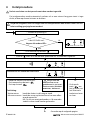
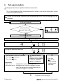
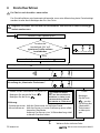
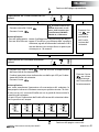
4 Set-up procedure
The panel must be set up after it has been connected.
The set up procedure will be exited automatically if no key is pressed for more than a minute,
or by pressing the on/o key.
• Switch on the power.
Is the ‘ON’ LED on?
Ignore all other LEDs.
• Press the key once.
• Press and hold the key for approx. 10 seconds.
• Hold the oat in the FULL position.
• Press the key once.
• Press the key.
Explanation:
- Float sensor: hold the oat in the highest position.
- Ultrasonic sensor: hold the sensor close to a reective surface.
Note: The sensor must be held steady in this
position for approx. 10 seconds.
OR
• Press the
key to
bypass setting
the ‘Maximum
tank level’.
Setting the ‘Maximum tank level’.
YES
NO
Always start the set up procedure from the beginning, even if only one setting has to be
changed!
AContinue on the next page.
Make sure that an
ultrasonic sensor has been
calibrated; see ‘Installation
instructions SENSORA’
090429.01, ‘Calibration’.

090427.02 17
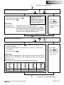
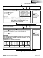
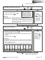
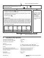
Waste water control panel WWCP
OR
• Press the
key to
bypass setting
the ‘Minimum
tank level’.
Setting the ‘Minimum tank level’.
• Hold the oat in the EMPTY position.
• Press the key once.
• Press the key.
Explanation:
- Float sensor: hold the oat in the lowest position.
- Ultrasonic sensor: hold the sensor at a distance from a reective
surface equal to the height of the tank.
Note: The sensor must be held steady in this
position for approx. 10 seconds.
Setting the ‘Finishing time’
• Press the key repeatedly to move through the possible settings.
The set value will be shown by one of the ‘Tank level’ LEDs.
• Press the key.
Explanation:
After the tank has been emptied, the pump can still run for a few min-
utes. This is desirable if the level sensor does not measure over the
whole range of the tank.
The tank level LEDs show the nishing times:
100%
50%
75%
25%
100%
50%
75%
25%
100%
50%
75%
25%
100%
50%
75%
25%
100%
50%
75%
25%
30 s 5 min 10 min 20 min 30 min
OR
• Press the
key to by-
pass setting the
‘Finishing time’.
A
BContinue on the next page.
Continued from previous page.
Make sure that an
ultrasonic sensor has been
calibrated; see ‘Installation
instructions SENSORA’
090429.01, ‘Calibration’.
ENGLISH

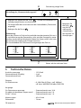
18 090427.02 Waste water control panel WWCP
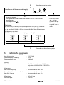
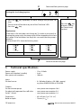
Setting the ‘Level changing time’
• Press the key repeatedly to move through the possible set-
tings.
The set value will be shown by one of the ‘Tank level’ LEDs.
• Press the key.
Explanation:
If the level in the tank does not change by 2% within a set time of ac-
tivating the pump cycle, the pump cycle will be stopped and an alarm
will sound. If the level does not drop, this can mean that the pump is
blocked.
The tank level LEDs show the nishing times:
100%
50%
75%
25%
100%
50%
75%
25%
100%
50%
75%
25%
2,5 min 5 min 10 min
OR
Press the key
to bypass setting
the ‘Level chang-
ing time’.
BContinued from previous page.
CContinue on the next page.
5 Technical specications
Power supply : 12 or 24 Volts
Power consumption (standby) : 4 mA
Max. power consumption : 100 mA
Input:
For level sensor : 0 - 300 ohm (0 ohm = full, 300 = empty)
e.g. Vetus WWSENSORA or SENSORA
Outputs:
For waste water pump : max. power consumption 10 A
For electrically operated shut-o valve : max. power consumption 5 A
For WC / Alarm : max. power consumption 1 A
Dimensions : 85 x 85 mm (3 3/8” x 3 3/8”)
Build-in depth : 78 mm (3 1/16”)

090427.02 19
Waste water control panel WWCP
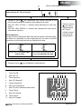
• Press the key to exit Set-up.
Setting the ‘Type of shut-o valve’.
• Press the key to select ‘manually operated shut-o valve’ or
‘electrically operated shut-o valve with status feedback’.
- 100% LED ON: => Shut-o valve without status feedback (manually
operated).
- 100% LED OFF: => Shut-o valve with status feedback (electrically
operated).
Explanation:
The LEDs used to indicate the tank level show whether the panel has
been set for a manually operated shut-o valve or an electrically oper-
ated shut-o valve with status feedback.
100%
50%
75%
25%
100%
50%
75%
25%
Manually operated shut-o
valve without status feed-
back
Electrically operated shut-o
valve with status feedback
OR
• Press the
key to
bypass setting
‘Type of shut-o
valve’ and to exit
Set-up.
CContinued from previous page.
vetus
WASTE CONTROL
100%
50%
75%
25%
1 2 3 4 5 6
7 8 9 10 11
1. ‘On/O’ key
2. ‘On’ LED
3. ‘Manual operation’ key
4. ‘Manual Operation’ LED
5. ‘Auto’ key
6. ‘Auto’ LED
7. Tank level LEDs
8. ‘Key’ key
9. ‘Shut-o valve’ key
10. ‘Key’ key
11. ‘Pump’ LED
ENGLISH

20 090427.02 Waste water control panel WWCP
1 Einleitung
Diese Schalttafel für die Schmutzwasseranlage (Waste Water Control Panel) zeigt mithilfe von
Leuchtdioden die vier verschiedenen Flüssigkeitsstände des Schmutzwassertanks an (25 %, 50 %,
75 %, 100 % voll) an. Wenn der Tank voll ist, wird dies mit einer rot blinkenden 100%-Leuchtdiode
angezeigt.
Die Bedienungstafel verfügt über einen Einschaltschutz, der verhindert, dass die Pumpe verse-
hentlich eingeschaltet wird. Durch Drücken einer Tastenkombination wird der Einschaltschutz
ausgeschaltet und kann die Pumpe - automatisch oder manuell – eingeschaltet werden. Bei ein-
geschalteter automatischer Tanküberwachung (AUTO-Modus) wird der Schmutzwassertank auto-
matisch geleert, wenn er voll ist. Wenn der Schmutzwassertank leer ist, wird die Pumpe automa-
tisch ausgeschaltet, um ein unerwünschtes Trockenlaufen zu vermeiden.
Die Tafel ist an einen im Schmutzwassertank montierten Vetus Niveausensor anzuschließen. Ge-
eignete Sensoren sind der Sensor mit Schwimmerarm, Art.-Kode: WWSENSORA, und der analoge
Ultraschallsensor, Art.-Kode: SENSORA.
Der digitale Ultraschallsensor, Art.-Kode: SENSORD, ist nicht geeignet!
Die Tafel verfügt über einen zusätzlichen Ausgang, mit dem ein Relais verstärkt werden kann, das
den Strom zur Toilette bzw. zur Wasserpumpe unterbricht. Dieses Relais wird verstärkt, wenn der
Tank zu 90 % gefüllt ist.
Außerdem kann ein elektrisch bedientes Absperrventil – falls installiert – an die Tafel angeschlos-
sen werden. Wenn der Tank zu 90 % gefüllt ist, wird zunächst das Absperrventil automatisch ge-
önet und anschließend wird die Schmutzwasserpumpe eingeschaltet. Eine Leuchtdiode auf der
Tafel signalisiert, wenn das Absperrventil (falls entsprechend angeschlossen) geschlossen ist.
Wird das maximale Flüssigkeitsniveau gelegentlich bzw. kurzfristig beispielsweise durch Bewe-
gungen des Schis erreicht, werden die entsprechenden Spitzenwerte ignoriert; das Niveau muss
längere Zeit und unabhängig von den Umständen den Maximalwert erreicht haben, bevor der
Absperrventil und die Schmutzwasserpumpe eingeschaltet werden.
Die Bedienungstafel wird ohne Zubehör wie Schmutzwasserpumpe, Absperrventil und Niveau-
sensor geliefert.
achtung
Führen Sie das „Einstellverfahren“ durch, bevor die Tafel in Betrieb genommen wird!
DEUTSCH
La pagina si sta caricando...
La pagina si sta caricando...
La pagina si sta caricando...
La pagina si sta caricando...
La pagina si sta caricando...
La pagina si sta caricando...
La pagina si sta caricando...
La pagina si sta caricando...
La pagina si sta caricando...
La pagina si sta caricando...
La pagina si sta caricando...
La pagina si sta caricando...
La pagina si sta caricando...
La pagina si sta caricando...
La pagina si sta caricando...
La pagina si sta caricando...
La pagina si sta caricando...
La pagina si sta caricando...
La pagina si sta caricando...
La pagina si sta caricando...
La pagina si sta caricando...
La pagina si sta caricando...
La pagina si sta caricando...
La pagina si sta caricando...
La pagina si sta caricando...
La pagina si sta caricando...
La pagina si sta caricando...
La pagina si sta caricando...
La pagina si sta caricando...
La pagina si sta caricando...
La pagina si sta caricando...
La pagina si sta caricando...
La pagina si sta caricando...
La pagina si sta caricando...
La pagina si sta caricando...
La pagina si sta caricando...
-
 1
1
-
 2
2
-
 3
3
-
 4
4
-
 5
5
-
 6
6
-
 7
7
-
 8
8
-
 9
9
-
 10
10
-
 11
11
-
 12
12
-
 13
13
-
 14
14
-
 15
15
-
 16
16
-
 17
17
-
 18
18
-
 19
19
-
 20
20
-
 21
21
-
 22
22
-
 23
23
-
 24
24
-
 25
25
-
 26
26
-
 27
27
-
 28
28
-
 29
29
-
 30
30
-
 31
31
-
 32
32
-
 33
33
-
 34
34
-
 35
35
-
 36
36
-
 37
37
-
 38
38
-
 39
39
-
 40
40
-
 41
41
-
 42
42
-
 43
43
-
 44
44
-
 45
45
-
 46
46
-
 47
47
-
 48
48
-
 49
49
-
 50
50
-
 51
51
-
 52
52
-
 53
53
-
 54
54
-
 55
55
-
 56
56


Vetus WWCP Waste Water Control Panel Manuale utente
- Tipo
- Manuale utente
in altre lingue
- English: Vetus WWCP Waste Water Control Panel User manual
- français: Vetus WWCP Waste Water Control Panel Manuel utilisateur
- español: Vetus WWCP Waste Water Control Panel Manual de usuario
- Deutsch: Vetus WWCP Waste Water Control Panel Benutzerhandbuch
- Nederlands: Vetus WWCP Waste Water Control Panel Handleiding
Documenti correlati
-
Vetus Complete tank type WWS Guida d'installazione
-
-
Vetus ILTCONW Guida d'installazione
-
-
-
-
-
-
-