Premier Mounts GB-MS2 Manuale utente
- Categoria
- Parete
- Tipo
- Manuale utente

Page 1 Installation Instructions
Storage GearBox™ for CTM-MS2 Tilting Mount - Installation Instructions
9541-001-011-01
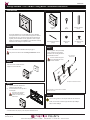
Parts List
GB-MS2MK
Media Box
(Qty 1)
Horizontal Support Bracket
(Qty 2)
M8 Nylon Nut
(Qty 4)
The storage GearBox™ for the CTM-MS2 tilting mount (GB-MS2)
securely holds a PC tower or similar-sized A/V equipment in between
the at-panel and mount. This space-saving feature helps efciently
organize your A/V installation for many applications, such as digital
signage or corporate use. The GB-MS2 is a great alternative to storing
electronics in false ceilings or bulky oor boxes.
• All trademarks are the property of the respective trademark owners.
Extension Bracket
(Qty 2)
Step 1
Follow the instructions in the CTM-MS2 manual up to page 7.
Stop at the end of the manual’s “Installing the Wall Plate” section.
Step 4
Use four (4) M8 x 12mm pan Phillips
screws to attach two (2) extension
brackets to the mounting brackets of
the CTM-MS2 as shown.
Insert the screws through the
back of the PEM nuts on the
extension brackets.
Mounting brackets are included with the CTM-MS2.
Screws are not to scale.
M8 x 12mm
Pan Phillips Screw
(Qty 4)
M8 x 12mm pan
Phillips screw
Key
(Qty 2)
Step 5
Is the mounting pattern on the at-panel wider than the media box?
If Yes, do not use the horizontal support brackets. Skip to Step 7.
If No, continue to Step 6.
Step 3
Insert a PC tower or similar-sized A/V
equipment into the media box.
Step 2
1) Insert the media box between the
brackets and the wall plate.
2) Hook the media box on the top rail of
the wall plate.
The lock on the media box
must be in the unlocked
position, or else it will not t
over the rail.
Flat-panel and brackets not shown
PC
Introduction
1321 S. State College Blvd. Fullerton, CA 92831 P 800-368-9700 F 714-632-1044 www.mounts.com

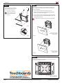
Page 2 Visit Premier Mounts website at www.mounts.com Installation Instructions
GB-MS2MK
Step 8
Step 7
Follow the rest of the instructions in the CTM-MS2 manual (starting on
page 8) to attach the mounting brackets and extension brackets to the
at-panel and wall plate.
• If you are using the horizontal support brackets, attach the
at-panel mounting hardware to the horizontal support brackets
instead of the mounting brackets (Figure 1).
• If you are not using horizontal support brackets, attach the at-panel
mounting hardware directly to the extension brackets instead of the
mounting brackets (Figure 2).
The at-panel mounting hardware is included with the CTM-MS2.
Once the at-panel is hung, route cables and electrical wiring through the
openings in the CTM-MS2 and media box.
Front view of CTM-MS2 and GB-MS2 with
horizontal support brackets
Figure 1
Figure 2
Flat-Panel
Flat-Panel
Flat-panel mounting pattern
smaller than width of media box.
CTM-MS2 not shown.
Flat-panel mounting pattern
wider than media box.
CTM-MS2 not shown.
Step 6
Use four (4) M8 nylon nuts to attach
two (2) horizontal support brackets to
the extension brackets (Figure 1).
Insert the nuts on the pegs
that are on the backs of the
horizontal support brackets
(Figure 2).
M8 nylon nut
Figure 1
Figure 2
Screws are not to scale.
-
 1
1
-
 2
2


Premier Mounts GB-MS2 Manuale utente
- Categoria
- Parete
- Tipo
- Manuale utente
in altre lingue
- English: Premier Mounts GB-MS2 User manual
Altri documenti
-
Tamiya M-03R Manuale del proprietario
-
ACI Farfisa Profilo CD2138PL Manuale del proprietario
-
-
-
 Volvo Penta AQAD30/DP Instruction book
-
Renishaw MH8 Guida utente
-
-
-
Bticino T7414ASS630 Istruzioni per l'uso
-
Lifetime 60054 Manuale del proprietario
