
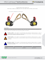
MSA Latchways
®
Vertical Device
LadderLatch, TowerLatch, TowerLatch SP and Climblatch
1
Latchways, an MSA Company.
Vertical fall arrest device to
EN 353-1:2002 & CNB/P/11.073 and EN 353-1:2014 /prA1:2017.
Important
Carefully read all of the safety and user instructions before using this product; paying particular attention to all
sections of these user instructions that carry warning symbols and notices.
Warning symbol. This symbol is used throughout the instructions whenever there is a risk of
personal injury or death to either the installer or end user of the product. Ensure that these warnings
are read and understood and followed at all times.
Caution symbol. This symbol is used throughout the instructions whenever there is a risk of
damaging the Latchways product. Ensure that these cautions are read and understood and followed
at all times.
Mandatory symbol. This symbol is used throughout the instructions whenever there is a specific
instruction for Latchways product. Ensure that these important instructions are read and understood
and followed at all times.
Document number
Issue number
Change request
Date of issue
Verti_96
9
100123
13/1/2017
Verti_96
10
100223
07/07/2017
Part number / identification of device type

MSA Latchways
®
Vertical Device
LadderLatch, TowerLatch, TowerLatch SP and Climblatch
2
Latchways, an MSA Company.
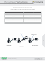
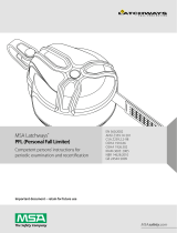
IDENTIFICATION OF DEVICE TYPE
(Part number is to be found on the device label)
Part number
Device type
35429-00
TowerLatch SP Device (see section 1.7)
3100L-00T
LadderLatch Device
3100L-00AC
LadderLatch AC Device
3102L-00
TowerLatch Device
3102L-00AC
TowerLatch AC Device
3103L-00
LadderLatch Device (Canada)
3104L-00
LadderLatch Device (USA)
3105L-00
TowerLatch Device (USA)
Webbing strop
Additional cover
LadderLatch
TowerLatch
AC Type Devices

MSA Latchways
®
Vertical Device
LadderLatch, TowerLatch, TowerLatch SP and Climblatch
3
Latchways, an MSA Company.
Contents
1. Safety instructions.
2. Product specification.
3. Required equipment.
4. Requirements for use.
5. Before use checks.
6. User instructions.
7. Materials.
8. Disposal
9. Inspection, maintenance and storage.
10. Markings.
11. Product Card.
12. EC Declaration of Conformity.
13. Appendix 1 - ClimbLatch
Installer company details
Company Name
Company Address
Contact Name
Tel No
Email

MSA Latchways
®
Vertical Device
LadderLatch, TowerLatch, TowerLatch SP and Climblatch
4
Latchways, an MSA Company.
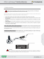
Shock pack label
Date of manufacture
1. Safety instructions
When using the Latchways vertical device, basic on site safety precautions, including the
following, should be observed to ensure personal safety.
All Users of the Latchways vertical devices shall be trained and competent in its safe use and shall read and
follow these instructions. Retain these instructions for future reference.
Never allow more than one person to attach to the Latchways vertical device at any time.
Before use always visually check and inspect the system for any faults, ensuring it is secure and has a valid
test certificate.
Always use a full body harness complying with national standards. Waist belts are not suitable for use with
this device.
Before use ensure the karabiner attaching the Latchways vertical device to the harness is in the closed and
locked position.
Do not use the Latchways vertical device for work positioning (i.e. primary means of support); to support
either partial or full body weight.
3100L, 3102L, 3103L, 3104L & 3105L type devices Maximum Rated Load (for systems incorporating a single
6 kN coil energy absorber) – The system can be used by a maximum of 3 Users. The total maximum rated load
for the system shall not exceed 400 kg (880 lbs) (total User weight including tools and equipment carried). The
maximum rated load for a single device shall not exceed 150 kg (330 lbs) (single User weight including tools
and equipment carried).
35429-00 TowerLatch SP device Maximum Rated Load – The maximum weight of any User (including tools
and equipment carried) should not exceed 100kg (220 lbs) unless the following label is visible on the energy
absorber indicating 150Kg (330 lbs) User weight is permissible.
Warning!
Only TowerLatch sp devices with a label indicating the maximum User weight are suitable for
users up to 150kg (330 lbs) all other devices that do not have a label indicating the maximum
User weight are only suitable for users up to 100kg (220 lbs).

MSA Latchways
®
Vertical Device
LadderLatch, TowerLatch, TowerLatch SP and Climblatch
5
Latchways, an MSA Company.
The minimum mass of User on any device including tools and equipment must not be less than 50 kg
The required minimum distance below the User’s feet and the ground is 2 m (6’6”). Below 2 m (6’6”) the
user may not be protected against hitting the ground or obstacles below. Therefore, extra care must be
taken when ascending / descending the first 2 m (6’6”).
Temporarily disabling or manually handling the lock/release mechanism of the device during ascent or
descent may hinder the safe operation and diminish the effect of the braking mechanism.
Before and during operation of the vertical fall arrest system consideration should be given as to how any
rescue could be safely and efficiently carried out.
The Latchways devices have been subjected to an additional series of tests devised by TUV/NEL (Notified
Body no. 0320). These tests were conducted using 71 kg (156 lbs) and 100 kg (220 lbs) anthropomorphic
test dummies with different body postures (reference NEL certificate no. MTHH).

MSA Latchways
®
Vertical Device
LadderLatch, TowerLatch, TowerLatch SP and Climblatch
6
Latchways, an MSA Company.
The following medical conditions could affect the safety of the User:
heart disease / chest pain.
high blood pressure.
epilepsy, fits, blackouts.
fear of heights / vertigo.
giddiness / difficulty with balance.
impaired limb function.
alcohol or drug dependence.
psychiatric illness.
diabetes.
Do not modify or alter the Latchways device without prior consent in writing from Latchways
plc.
The Latchways device is not to be used for any other use than providing attachment for one
User to a Latchways cable system. During use do not allow any clothing, equipment,
appendages or any other items to restrict the operation of the device.
If the Latchways is resold for use outside the original country of destination the reseller shall
provide instructions for use, maintenance and periodic examinations in the language of the
country of destination.
The device is only to be used to provide an attachment for one User to a Latchways vertical
cable system. All system components shall be manufactured and specified by Latchways
plc. The cable shall be Ø8 MM (5/16”) 1 X 19 construction grade 316 stainless steel to
BS.MA 29 or AISI 316
Do not use the device at temperatures below -30 °c.

MSA Latchways
®
Vertical Device
LadderLatch, TowerLatch, TowerLatch SP and Climblatch
7
Latchways, an MSA Company.
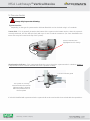
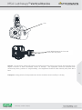
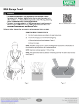
2. Product specification
The device is designed to arrest the fall of one climber in conjunction with a Latchways vertical fall arrest
system.
If a climber were to fall whilst connected to the Latchways system the energy absorber will deploy and
reduce the load applied to the body to 6 kN (1,350 lbf) or less.
The device has an anti-inversion mechanism which prevents it being used on the cable system if there is an
attempt to use it upside down.
When the device is attached to the cable the horizontal distance from the cable to the harness front
attachment point is 0.3 m, (12”) which allows the user to ascend / descend unhindered, this must not be
extended, shortened or have any components added or removed
The full arrest distance of the device when tested to CSA Z259.2.5 is less than 150 mm (6”).
Label contents will vary to comply with applicable regional Standards
Karabiner
Starwheel
Link
Buffer
Release Catch
Cover
Slipper Pad
Release catch cover

MSA Latchways
®
Vertical Device
LadderLatch, TowerLatch, TowerLatch SP and Climblatch
8
Latchways, an MSA Company.
3.
Required equipment
A full body harness with a chest and dorsal attachment point which complies with the appropriate national
standards. Waist belts are not suitable for use with this device. The full body harness must be properly fitted
ensuring all buckles are correctly adjusted and connected together where appropriate, harnesses that include
elastic webbing at the front connection point are not suitable for use with this device.
A helmet with chin strap which complies with the appropriate national standards.
4. Requirements for use
Personnel using this device shall be trained and competent in safe methods for working at height. If any of
these instructions are not understood, please contact your supplier. All Users of the system shall comply with
the instructions and guidance contained in these instructions and those highlighted on the warning label attached
to the Latchways vertical GTFA device. The Latchways vertical GTFA device shall only be used by persons
deemed to be competent and their names recorded on the record card. All Users should confirm in writing that
they have read and fully understood the user instructions and any other pertinent safety information.
Before undertaking work at height and at regular intervals during the period of work, a risk assessment shall be
carried out.
The Latchways vertical GTFA device shall be directly attached to the front chest position of a full body harness
when used on a vertical system
All users must ensure that a minimum distance of 3 m (9‘10”) is maintained between the head of each user and
the feet of the user immediately above that user.
The Latchways vertical GTFA device must only be engaged or disengaged from the system whilst the User is
in a safe position, a safe position is where there is no risk of a fall occurring.

MSA Latchways
®
Vertical Device
LadderLatch, TowerLatch, TowerLatch SP and Climblatch
9
Latchways, an MSA Company.
5. Pre-use checks
Always fully inspect the following:
System tension
Depending on the type of system tension indicator fitted this can be checked using 1 of 2 methods.
Tenser disk – This is generally located at the bottom of the system on the bottom anchor, when the system is
correctly tensioned, the disc will spin freely with up to 2 mm of vertical movement. (On some installations the
tenser disc may be located at the top of the system).
Visual tension indicator – This component allows the user to check the system tension in situations where it
is impractical to reach a tension indicator disc from a position of safety.
If a fault is identified with system tension the system shall not be used and the issue raised with site supervision.
Tension indicator disc
(highlighted red for clarity)
Tension indicator guide
The system is correctly
tensioned when the tension
indicator guide is aligned
within the rebated area of
the front plate

MSA Latchways
®
Vertical Device
LadderLatch, TowerLatch, TowerLatch SP and Climblatch
10
Latchways, an MSA Company.
Device checks:
Latchways vertical GTFA device - The Latchways device shall be inspected before every use, the following
checks shall be made:
Check the condition of the linkage, ensure the linkage is not deformed.
Check that the star wheels spin freely and true on the axle.
Ensure that the release catch functions correctly, releasing the star wheel only when depressed and
allowing it to return to its original position.
Invert the device and press the release catch check to see if the star wheel is still locked and cannot be
pulled away from the body.
Check the cam moves freely.
Signs of corrosion, wear, deformation or other defects to the device.
Check the condition of the karabiner to ensure the gate locking mechanism works correctly.
Check that all plastic components are present, (Star wheel buffer and Slipper pad) and are not damaged.
Check the product label, all regulatory information (serial no, date of manufacture etc) shall be clearly
legible.
Ensure the device is within its service date.
If the Latchways vertical GTFA device fails any of the above criteria it shall be withdrawn from
service and returned to Latchways plc.
If the Latchways vertical GTFA device is damaged, there is any doubt about the safe condition
of the device or the service date has expired it shall be withdrawn from service. This shall be
recorded on the record card. Contact your authorised installer or agent for
further advice.
Ensure there is a rescue plan in place to deal with any emergencies which may arise and you
are fully aware of the procedure before attempting any work at height.

MSA Latchways
®
Vertical Device
LadderLatch, TowerLatch, TowerLatch SP and Climblatch
11
Latchways, an MSA Company.
6. User Instructions
If the device has been used to arrest a fall, is damaged or there is any doubt about the safe
condition of the device or the service date has expired it shall be withdrawn from service.
This shall be recorded on the record card.
Ensure there is a rescue plan in place to deal with any emergencies which may arise and
you are fully aware of the procedure before attempting any work at height.
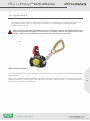
Connect the device via the karabiner to the chest attachment point of the harness by releasing the locking
safety gate on the karabiner. With the karabiner in the open position insert the open end of the karabiner
into the chest attachment point on the harness. Release the safety gate ensuring it is fully closed and
locked.
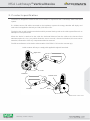
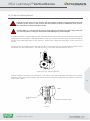
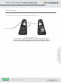
Hold the device in the right hand by the release catch cover below the level of the attachment point so that
the linkage is in the vertical plane. This will force the cam into the unlocked position. Fig 6.2.
Press the release catch with your right thumb. The release catch will not operate if the device is incorrectly
oriented. Using your left hand pull the Star wheel away from the body of the device and offer the device up
to the cable. Fig 6.3.
Fig 6.2. Cam in unlocked position.
Cable
Depress Release Catch
Pull Star wheel
Out
Fig 6.3.

MSA Latchways
®
Vertical Device
LadderLatch, TowerLatch, TowerLatch SP and Climblatch
12
Latchways, an MSA Company.
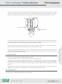
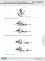
Move the device around the cable until the cable is held within the cavity in the body of the device. Remove
your thumb and allow the release catch to return. Finally allow the star wheel to move back into its original
position, check that the release catch has disengaged and the star wheel cannot be pulled out. Fig 6.4.
To check the device is fully engaged move the device up the cable then quickly pull down on the karabiner
the device should lock onto the cable. If this does not happen, remove the device from service and do not
use until the device has been recertified by a Latchways authorised agent.
When ascending and descending, the device shall always be below the harness chest attachment point.
The red slipper shall always be pointing upwards in contact with the cable.
To disconnect from the system, when you are in a safe position to do so, depress the release catch, pull the
star wheel out, hold the device below the harness attachment point so that the cam is open and then move
the device until it is free from the cable.
7. Materials
The device is manufactured from the following materials:
316 grade stainless steel, 17/4 PH stainless steel, steel, nylon 6 and ABS.
All metallic parts should be unaffected by sharp edges, chemical reagents, cutting, abrasion, UV degradation
or normal climatic conditions ranging from -30°C to 50°C. All metallic parts need to be kept a safe distance
from electrical current. 316 and 17/4 PH stainless steels shall not be exposed to environments containing
chlorine.
Nylon 6 (buffer) and ABS (release catch cover) should be kept clear of the following, sharp edges, chemical
reagents, cutting, abrasion, UV degradation. Avoid contact with electrical current.
8. Disposal
All stainless steel and plastic components are recyclable.
Cable
Disengage Release
Catch
Return Star wheel
Fig 6.4.

MSA Latchways
®
Vertical Device
LadderLatch, TowerLatch, TowerLatch SP and Climblatch
13
Latchways, an MSA Company.
9. Inspection, maintenance and storage
Periodic examination –The Latchways vertical GTFA device shall be examined at least every 12 months. Local
requirements, frequency of use or environmental conditions may dictate more frequent examinations.
Examinations shall only be conducted by a Latchways trained Technician in accordance with Vertical Devices -
Instructions for periodic examination, repair and recertification. The safety of the User depends upon the
continued efficiency and durability of the device.
The date of first use must be administratively provable. Where the date of first use is NOT known, the next
previous provable date must be used, e.g, date of purchase/date of manufacture of the device. There are no
user serviceable parts within the device.
Lifespan- The webbing elements of Latchways vertical GTFAs (webbing strop and energy absorber on
TowerLatch and TowerLatch SP devices) have a maximum lifespan of 10 years from the date of manufacture.
ISC branded karabiners have an unlimited lifespan, all other karabiners have a maximum lifespan of 10 years
from the date of manufacture. (5 years if manufactured before April 2015) This is subject to passing periodic
examinations.
This is subject to passing periodic examinations.
Cleaning – As part of general maintenance the Latchways vertical GTFA device may require cleaning from time
to time this may be done using warm water and a domestic detergent. The device should be thoroughly rinsed
and dried naturally away from direct heat.
Do not use any solvents, thinners or any chemical cleaning agent.
If it is anticipated that the device is to be used in wet, very cold conditions between -4 and -30°C apply a small
amount of WD 40 water dispersant to the area between the cam and the side plates. Following application of
the WD 40 allow any excess dispersant to drain away and wipe any surplus from the device using a clean lint
free cloth. Never use cleaning agents containing chlorine or Chlorides.

MSA Latchways
®
Vertical Device
LadderLatch, TowerLatch, TowerLatch SP and Climblatch
14
Latchways, an MSA Company.
Storage - The Latchways vertical GTFA device should be stored away from excessive heat, high humidity, sharp
edges, corrosives or other foreseeable causes of damage. The equipment should be protected from
unnecessary stress, pressure or rough handling. Wet equipment should be dried naturally away from direct
heat.
Transport - during periods of transportation the device should be stored carefully in a kit bag.
Apply WD40 between the Cam and
each of the side plates.
Cam

MSA Latchways
®
Vertical Device
LadderLatch, TowerLatch, TowerLatch SP and Climblatch
15
Latchways, an MSA Company.
10. Markings
The following markings are shown on the Latchways LadderLatch device
For illustrative purposes only:
Example shown is model 3100L-00 for BS EN 353-1:2002 jurisdictional regions.
3103L-00 will be labelled appropriately for CSA.Z259.2.1 jurisdictional regions.
3104L-00 will be labelled appropriately for ANSI Z359.1-2007 jurisdictional regions.
Use this way up only
Read these
instructions before use

MSA Latchways
®
Vertical Device
LadderLatch, TowerLatch, TowerLatch SP and Climblatch
16
Latchways, an MSA Company.
11. Product record card
This card should be filled in on receipt of the device and on receipt after every service.
Equipment Record
Product : LadderLatch Device conforms to BS EN 353-1 2002 / CSA Z259.2.1 /
ANSI Z359.1-2007 & AS/NZS 1981.3-1997
Model &
Type/Identification :
Trade name : Latchways
LadderLatch device
Serial Number :
Manufacturer:
Latchways PLC
Address :
Hopton Park, Devizes
Wiltshire SN10 2JP
Tel: +44 (0)1380 732700
Fax: +44 (0)1380 732701
Year of Manufacture /
Life expiry date :
Purchase Date :
Date First Put into Service :
Periodic Examination and Repair History
Date
Reason for
entry
(periodic
examination
or repair)
Defects noted,
repairs carried out
and other relevant
information
Name &
Signature of
Competent
Person
Periodic
Examination
Next Due
Date

MSA Latchways
®
Vertical Device
LadderLatch, TowerLatch, TowerLatch SP and Climblatch
17
Latchways, an MSA Company.
12. EC Declaration of Conformity
EC DECLARATION OF CONFORMITY
The manufacturer or his authorised representative
established in the community:
Latchways plc
Hopton Park, Devizes
Wiltshire SN10 2JP
England
Declares that the new PPE described hereafter
VERTICAL FALL ARREST SYSTEMS
is in conformity with the provisions of Council Directive 89/686/EEC and, where such is the case,
with the national standard transposing harmonised standard No EN353-1 and VG11
recommendations for use CNB/P/11.073 (for the PPE referred to in article 8(4)) is identical to
the PPE which is the subject of EC certificate of conformity No ZB049/95 issued by:-
DEKRA EXAM GmbH (Notified Body No: 0158 – formerly DMT)
Dinnendahlstrasse 9
44809 Bochum
Germany
and is subject to the procedure set out in Article 11 point B of Directive 89/686/EEC under the
supervision of the notified body:-
INSPEC International Limited (Notified Body No: 0194)
56 Leslie Hough Way,
Salford, Greater Manchester,
M6 6AJ,
England
June 2012
T. Bissett
Technical Manager

MSA Latchways
®
Vertical Device
LadderLatch, TowerLatch, TowerLatch SP and Climblatch
18
Latchways, an MSA Company.
13. Appendix 1.
Additional information relating to the use of Latchways ClimbLatch devices
on guided type vertical fall arrest systems in conformance with EN353-
1:2014/prA1:2017.
When using the Latchways Climblatch device on an inclined or vertical system the arrow on the
device label and the red slipper pad must always be pointing towards the highest point of the
system. Under no circumstances must the device be used the other way around.
User Instructions
On a vertical system - connect the Latchways ClimbLatch device via the karabiner to the chest attachment point
of the harness.
Entry to the system is identical whether for a vertical, inclined or horizontal system. Hold the cam link in the
position shown in Fig1. This will ensure the cable grip cam is held in the open position. Unscrew the thimble on
the entry gate and slide the thimble away.
Up

MSA Latchways
®
Vertical Device
LadderLatch, TowerLatch, TowerLatch SP and Climblatch
19
Latchways, an MSA Company.
Hold link here
Fig 1. Cable grip cam
Offer the ClimbLatch device to the gap in the entry gate. Ensure the slipper is positioned underneath the tube,
push the slipper along the tube see fig 2.
Fig 2
Once the ClimbLatch device is fully engaged with the tube pull the device along until the gap has been
cleared. Next tighten up the thimble on the entry gate to secure the system. Fig 3.
Fig 3
System set up is now complete.
-
 1
1
-
 2
2
-
 3
3
-
 4
4
-
 5
5
-
 6
6
-
 7
7
-
 8
8
-
 9
9
-
 10
10
-
 11
11
-
 12
12
-
 13
13
-
 14
14
-
 15
15
-
 16
16
-
 17
17
-
 18
18
-
 19
19


Latchways Latchways TowerLatch SP Manuale utente
- Tipo
- Manuale utente
- Questo manuale è adatto anche per
in altre lingue
Documenti correlati
-
MSA Latchways SRL Serie Istruzioni per l'uso
-
 Latchways Personal Rescue Device® Istruzioni per l'uso
-
 Latchways V-TEC™ Personal Fall Limiter Istruzioni per l'uso
-
MSA WinGrip® Vacuum Anchor Manuale del proprietario
-
Latchways Sealed Self-Retracting Lanyards Istruzioni per l'uso
-
 Latchways WinGrip® Vacuum Anchor Manuale del proprietario


Altri documenti
-
MSA Latchways Fall Arrester Manuale utente
-
-
MSAsafety WINGRIP-CUSTOM Manuale utente
-
MSA Latchways Self Reracting Lifeline Manuale utente
-
 P&P EN358 Manuale utente
-
-
STIHL Msa 200 c Manuale utente
-
Videotec NXPTZR SERIES2 Manuale utente
-
-
STIHL MSA 200 C-B Manuale utente
