
CARLO GAVAZZI
Automation
Components
Eos Array
01 02
B
A
G
B
A
G
11 13 23 21 11 13 23 21
11 12 13 21 22 23
LED RGB MULTICOLOR FUNCTION. Green steady light: the module is power supplied and there is no communication
on the RS485 bus. Green blinking light: the communication on the RS485 bus is working. Red: alarm detected (any).
In case of alarm/communication condition the LED alternates its colour from red (alarm) to green. The blinking time is
approx. 1 second.
MESSAGGES. Conn.CY: Fuse blow detection. Alarm occurs 30 minutes after the fuse has blown providing at least one
of the fuses is still working and the system is measuring power. StrinG: String failure warning: the “String control” function
has detected a failure. The STRING information is given in combination with the LED alarm on VMU-M and the LED
colour code on every single string. Conn.PY: The string is wrongly connected (reverse polarity). SYStEM: Power-up
self-test error. NOTE: first power-up: the VMU-M module acquires the modules lay-out recognizing the kind of modules
in every position in the auxiliary network. The network configuration is stored into the VMU-M module. Following power-
ups: the VMU-M module acquires the modules lay-out recognizing the kind of modules in every position in the auxiliary
network comparing it with the former stored configuration. The comparison can have two results:
- the stored configuration is equal to the actual configuration, no actions taken by the module; - the stored configuration
is different from the actual configuration. In this case an alarm occurs, this is stored into the VMU-M module and logged
as an event. buS: Auxiliary bus communication error. NOTE: in case of bus error all data are stored. ALArM: Variables
alarm (any).
PUSH BUTTON. To program the configuration parameters and to scroll the variables. One key function: short time
pushbutton click: variable scroll or parameter increasing. Long time pushbutton click: programming procedure entering,
parameter selection confirmation.
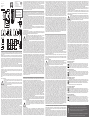
WIRING DIAGRAMS.
[1] Power supply 12-28VCC. [2] Digital input 1 e 2. [3] Temperature input 1 and 2, 3 wires connections. [4] Temperature
input 1 and 2, 2 wires connections. [5] RS485 serial port communication. RS485 NOTE: the termination of the serial
output is carried out only on the last instrument of the network, by means of the proper termination resistance (T)
included.
SAFETY PRECAUTIONS
Read carefully the instruction manual. If the instrument is used in a manner not specified by the
producer, the protection provided by the instrument may be impaired. Maintenance: make sure that
the connections
are correctly carried out in order to avoid any malfunctioning or damage to the instrument. To keep the
instrument clean, use a slightly damp cloth; do not use any abrasives or solvents. We recommend to
disconnect the instrument before cleaning it.
TECHNICAL SPECIFICATIONS
Display 1 line (max: 6-DGT) Type LCD, h 7mm. Information read-out From 4 to 6-DGT depending on the information.
Digital inputs, number of inputs 2. Working mode, first input: detection of ON/OFF status Second input: counting of
pulses coming from an energy meter. Purpose - First input: trip of protection detection, the status is transmitted only by
means of the communication port. - Second input: trip counter, interfacing with an energy meter (-kWh) so to measure
the total efficiency of the system (BOS). Input frequency 20Hz max, duty cycle 50%. Pre-scaler adjustment, from
0.001 to 10.000 kWh/pulse (only for the second input). Contact measuring voltage 3.3VDC. Contact measuring cur-
rent <1mA. Contact resistance ≤1kΩ closed contact; ≥20kΩ open contact. Temperature inputs, number of inputs 2,
temperature probe Pt100, Pt1000. Number of wires 2 or 3-wire connection. Wire compensation up to 10Ω. Accuracy
(Display + RS485) See “Temperature input characteristics” in the relevant data sheet. Temperature drift ±150ppm.
Engineering unit selectable °C or °F. Insulation see the table “Insulation between inputs and outputs” in the relevant
data sheet. Key-pad 1 push-button for variable scrolling and programming. Full programming can be carried out only
using Eos-ArraySoft. RS485 type Multidrop, bidirectional (static and dynamic variables). Connections 2-wire. Max.
distance 1000m. Addresses 247, selectable by means of the front push button. Protocol MODBUS/JBUS (RTU). Data
(bidirectional) dynamic (reading only) all variables, see table “Measured variables, data format and messages” in the
VMU-S document. Static (writing only) all the configuration parameters. Data format 1 start bit, 8 data bit, no parity,1
stop bit. Baud-rate selectable: 9600, 19200, 38400, 115200 bits/s. Driver input capability. Parity: none. Special functions
1/5 unit load. Maximum 160 transceivers on the same bus. Auxiliary communication bus this is the communication bus
to the VMU-S, VMU-P and VMU-O units where VMU-M performs the master function in this network. VMU-M unit can
gather the following information from the bus: - All variables available on the bus; - Blown protection fuse;
- PV connection problems; - PV reverse voltage and current polarity. The local address in both the VMU-S, VMU-P and
VMU O units is automatically assigned by VMU-M master unit based on their positions. It can manage up to 15 different
addresses (units). Operating temperature -25 to +55°C (-13°F to 131°F) (R.H. from 0 to <90% non-condensing @ 40°C).
Storage temperature -30 to +70°C (-22°F to 158°F) (R.H. < 90% non-condensing @ 40°C). Over voltage category Cat.
III (IEC 60664, EN60664). For inputs from string: equivalent to Cat. I, reinforced insulation. Dielectric strength 4000 VAC
RMS for 1 minute. Noise rejection CMRR 65 dB, 45 to 65 Hz. EMC (Immunity) According to EN61000-6-2. Electrostatic
discharges EN61000-4-2: 8kV air discharge, 4kV contact; Immunity to irradiated. Electromagnetic fields EN61000-4-3:
10V/m from 80 to 3000MHz; Immunity to Burst EN61000-4-4: 4kV on power lines, 2kV on single lines; Immunity to
conducted disturbances EN61000-4-6: 10V from 150KHz to 80MHz; Surge EN61000-4-5: 500V on power supply;
ENGLISH VMU-M
VMU-M
FUNZIONE LED RGB FRONTALE. Luce verde fissa: il modulo è alimentato e non c’è comunicazione sul bus seriale RS485.
Luce lampeggiante verde: c’è comunicazione sul bus seriale RS485. Luce rossa: indicazione di allarme (qualsiasi). In caso di
una condizione di allarme contemporanea alla comunicazione il LED si alterna rosso (allarme) e verde. Il tempo di lampeggio
è di circa una volta al secondo.
MESSAGGI. Conn.CY: Rilevamento fusibile interrotto. L’avviso avviene 30 minuti dopo l’effettiva interruzione del fusibile.
Le condizioni necessarie affinchè il controllo di interruzione si attui sono: la presenza di almeno un fusibile non interrotto;
il sistema stia misurando potenza. StrinG: allarme guasto stringa: la funzione “Controllo di stringa” ha rilevato un guasto.
L’informazione STRING si esprime in combinazione con il LED d’allarme sul VMU-M e il codice colore del LED su ogni
singola stringa. Conn.PY: la stringa è collegata in modo errato (polarità invertita). SYStEM: Errore di auto-test di avvio. NOTA:
alla prima accensione il modulo VMU-M acquisisce la composizione del sistema riconoscendo il tipo di modulo e la posizione
di montaggio nella rete. La configurazione di rete viene registrata all’interno del modulo VMU-M. Alla succesiva accensione il
modulo acquisice nuovamente la composizione della rete e la confronta con la precedente se riscontra delle differenze avvia
un’allarme che verrà registrato come evento. buS: errore di comunicazione del bus locale. NOTA: In caso di errore tutti i dati
vengono registrati. ALArM: allarme variabili (qualsiasi).
TASTO. Per la programmazione dei parametri di configurazione e per scorrere tutti i dispositivi. Funzionamento: breve
pressione del tasto: per scorrere le variabili o per incremento dei parametri. Lunga pressione del tasto: accesso alla procedura
di programmazione, conferma del valore impostato.
COLLEGAMENTI ELETTRICI
[1] Alimentazione 12-28VCC. [2] Ingresso digitale 1 e 2. [3] Ingresso in temperatura collegamento 3 fili. [4] Ingresso in
temperatura collegamento 2 fili. [5] Porta seriale RS485. NOTA RS485: la terminazione della rete deve essere eseguita solo
sull’ultimo strumento mediante la specifica resistenza di terminazione (T) in dotazione.
NORME DI SICUREZZA
Leggere attentamente il manuale istruzioni. Qualora l’apparecchio venisse adoperato in un modo non
specificato dal costruttore, la protezione prevista dall’apparecchio potrebbe essere compromessa.
Manutenzione: assicurarsi che i collegamenti siano effettuati correttamente al fine di evitare qualsiasi
malfunzionamento o danneggiamento dello strumento. Per mantenere pulito lo strumento usare un panno
leggermente inumidito; non usare abrasivi o solventi. Si consiglia di scollegare lo strumento prima di pulirlo.
CARATTERISTICHE TECNICHE
Display, 1 linea (max: 6-DGT) Tipo LCD, h 7mm. Informazioni visualizzate da 4 a 6-DGT a seconda delle informazioni.
Ingressi digitali numero d’ingressi 2. Modo di funzionamento primo ingresso: rilevamento dello stato contatto APERTO/
CHIUSO. Secondo ingresso: conteggio degli impulsi provenienti da un contatore di energia. Utilizzo - Primo ingresso:
rilevamento intervento protezione, lo stato è trasmesso solo mediante porta di comunicazione. - Secondo ingresso: se
interfacciato con un contatore di energia (kWh) per calcolare l’efficienza totale del sistema (BOS). Frequenza d’ingresso 20Hz
max, duty cycle 50%. Impostazione del pre-scaler da 0,001 a 10,000 kWh/ impulso (solo per il secondo ingresso). Tensione
di lettura contatto 3,3VCC. Corrente di lettura contatto <1mA. Resistenza del contatto ≤1kΩ contatto chiuso; ≥20kΩ contatto
aperto. Ingressi di temperatura numero d’ingressi 2. Sonda Pt100 o Pt1000 Tipo di collegamento connessione 2 o 3 fili.
Compensazione collegamenti fino a 10Ω. Precisione (Display e RS485) vedere “Caratteristiche dell’ingresso di temperatura”
nel relativo data sheet. Deriva di temperatura ±150ppm. Unità ingegneristica selezionabile °C o °F. Isolamento, vedere
“Isolamento tra ingressi ed uscite” nel relativo data sheet. Tasto il tasto permette di scorrere le variabili e alcuni parametri di
programmazione. La programmazione completa può essere eseguita solo mediante il software Eos-Array Soft. RS485 tipo
Multidrop, bidirezionale (variabili statiche e dinamiche). Connessioni 2 fili. Distanza Max. 1000m. Indirizzi 247, selezionabili
mediante tasto frontale. Protocollo MODBUS/JBUS (RTU). Dati (bidirezionali). Dinamici (solo lettura) Tutte le variabili. Statici
(solo scrittura) Tutti i parametri di configurazione. Formato dati 1 bit di start, 8 bit dati, nessuna parità,1 bit di stop. Velocità di
trasmissione selezionabile: 9.600, 19.200, 38.400, 115.200 bits/s. Parità: nessuna. Dispositivi in rete 1/5 unit load. Massimo
160 dispositivi nella stessa rete. Bus di comunicazione ausiliaria E’ il bus di comunicazione delle unità VMU-S, VMU-P e
VMU-O dove VMU-M ha la funzione di master. L’unità VMU-M raccoglie dal bus le seguenti informazioni: - Tutte le variabili
misurate dal sistema; - Interruzione del fusibile di protezione; - Problemi alla connessione del modulo FV; - Tensione e
corrente inversa del modulo FV. Gli indirizzi locali di VMU-S, VMU-P e VMU-O sono assegnati automaticamente dall’unità
master VMU-M basandosi sulla posizione di ciascun modulo. Può gestire fino a 15 indirizzi (unità) diversi. Temperatura di
funzionamento -25 to +55°C (da -13°F a 131°F) (U.R. da 0 a <90% senza condensa @ 40°C). Vedere anche “VMU-S
caratteristiche d’ingresso”. Temperatura di immagazzinamento -30 to +70°C (da -22°F a 158°F) (R.H. < 90% senza condensa
@ 40°C) Categoria d’installazione Cat. III (IEC 60664, EN60664) Per gl’ingressi di stringa: equivalente a Cat. I, isolamento
rinforzato. Isolamento (per 1 minuto). Rigidità dielettrica 4000 VAC RMS per 1 minuto. Reiezione CMRR >65 dB, da 45 a
65 Hz. EMC (Immunità) secondo EN61000-6-2. Scariche elettrostatiche EN61000-4-2: 8kV scarica in aria, 4kV contatto;
Immunità ai campi elettromagnetici irradianti EN61000-4-3: 10V/m da 80 a 3000MHz; Immunità ai transitori veloci EN61000-
4-4: 4kV sulle linee di alimentazione, 2kV su singole linee; Immunità ai radio disturbi condotti EN61000-4-6: 10V da 150KHz a
80MHz; Immunità ad impulso EN61000-4-5: 500V sull’alimentazione; 4kV sugli ingressi di stringa. EMC (Emissioni) secondo
EN61000-6-3. Emissioni in radiofrequenza secondo CISPR 22. Conformità alle norme sicurezza IEC60664, IEC61010-
1, EN60664, EN61010-1. Approvazioni CE, cULus Listed. Custodia dimensioni 17,5 x 90 x 67 mm. Materiale Noryl,
autoestinguenza: UL 94 V-0. Montaggio A guida DIN. Grado di protezione frontale IP40. Connessioni IP20. Alimentazione
da 12 a 28 VCC. Autoconsumo ≤1W.
LED-LEUCHTE. Grünes Festlicht: Das Modul wird mit Strom versorgt und es gibt keine Kommunikation an den Bus RS485.
Grünes Blinklicht: Die Kommunikation an den Bus RS485 läuft. Rot: Alarm erfasst (alle). Bei Alarm/ Kommunikationsbedingung
wechselt die LED-Leuchte ihre Farbe von rot (Alarm) auf grün. Die Blinkzeit beträgt ungefähr 1 Sekunde.
MELDUNGEN. Conn.CY: Erkennung Sicherungsfall. Alarm tritt 30 Minuten nach dem Sicherungsfall auf wenn noch
mindestens eine der Sicherungen noch funktioniert und das System Leistung misst. StrinG: Warnung für Stringfehlbetrieb:
die Funktion “Stringsteuerung” hat einen Fehlbetrieb erfasst. Die STRING-Information wird in Verbindung mit dem
LEDLeuchtenalarm an VMU-M und dem LED-Leuchtenfarbkode an jedem einzelnen String erteilt. Conn.PY: Der String ist
falsch angeschlossen (verkehrte Polarität). SYStEM: Einschaltfehler. ANMERKUNG: Ersteinschaltung: Das Modul VMU-M
gewinnt die Modulanordnung, indem es den Typ der Module in allen Positionen im Hilfsnetz erkennt. Die Netzkonfiguration
wird im Modul VMU-M gespeichert. - nachfolgende Einschaltungen: das Modul VMU-M gewinnt die Modulanordnung, indem
es den Typ der Module in allen Positionen im Hilfsnetz gewinnt und mit der zuvor gespeicherten Konfiguration vergleicht. Der
Vergleich kann zwei Ergebnisse ergeben: - die gespeicherte Konfiguration stimmt mit der aktuellen Konfiguration überein,
das Modul ergreift keine Maßnahmen; - die gespeicherte Konfiguration weicht von der aktuellen Konfiguration ab. In diesem
Fall tritt ein Alarm auf, er ist im Modul VMU-M gespeichert und wird als ein Ergebnis eingetragen. buS: Kommunikationsfehler
Hilfsbus. ANMERKUNG: Im Falle eines Busfehlers werden alle Daten gespeichert. ALArM: Messegrößenalarm (alle).
DRUCKTASTE. Zum Programmieren der Konfigurationsparameter und zum Durchlaufen der Messgrößen. Ein Tasten-
Funktion: Kurzer Klick der Drucktaste: Messgrößendurchlauf oder Zunahme der Parameter. Langer Klick der Drucktaste:
Login in das Programmierverfahren, Bestätigung der Parameterwahl.
ANSCHLÜSSE. [1] Stromversorgung 12-18VDC. [2] Digitaleingang 1 und Eingang 2. [3] Temperatureingang 1 und Eingang
2, 3-adriger Anschluss. [4] Temperatureingang 1 und Eingang 2, 2-adriger Anschluss. [5] RS485 Port. RS485 HINWEIS:
Der Abschluss des seriellen Netzwerkes wird nur am letzten Gerät durch den inkludierten Abschlusswiderstand ausgeführt.
SICHERHEITSBESTIMMUNGEN.
Die Betriebsanleitung aufmerksam lesen. Sollte das Gerät nicht gemäss der Herstellerangaben verwendet
werden, könnte der vom Gerät vorgesehene Schutz beeinträchtigt werden. Wartung: Beachten Sie den
korrekten Anschluss aller Anschlussterminals um eine Beschädigung des Instrumentes zu vermeiden. Das
Gerät mit einem feuchten Tuch reinigen; keine Scheuer- oder Lösemittel verwenden. Das Gerät vor der
Reinigung ausschalten.
TECHNISCHE DATEN
Display. 1 Linie (max: 6-DGT). Typ LCD, h 7mm. Informationsanzeige Von 4 bis 6- Digitaleingänge, Anzahl der Eingänge
2. Betriebsart Erster Eingang: Zustandserfassung ON/OFF Zweiter Eingang: Zählen der von Energiezähler kommenden
Impulse Zweck - Erster Eingang: Auslösung der Schutzmessung, der Zustand wird nur mit dem Kommunikationsport
übertragen. - Zweiter Eingang: Auslösezähler, Schnittstelle mit einem Energiezähler (-kWh) um die Gesamtleistung des
Systems (BOS) zu messen. Eingangsfrequenz Max 20Hz, Arbeitszyklus 50%. Verteilereinstellung. Von 0,001 bis 10,000
kWh/Impuls (nur für den zweiten Eingang). Kontakt für Spannungsmessung 3,3VDC. Kontakt für Strommessung <1mA.
Kontaktwiderstand ≤1kΩ geschlossener Kontakt. ≥20kΩ offener Kontakt Isolierung Siehe Tabelle “Isolierung zwischen Ein- und
DEUTSCH VMU-M
ITALIANO VMU-M
LED. Lumière verte fixe: le module est alimenté et il n’y a pas de communication sur le bus RS485. Lumière verte clignotante:
la communication sur le bus RS485 fonctionne. Rouge: alarme détectée (n’importe laquelle). En cas de situation d’alarme /
communication, les DEL passent de la couleur rouge (alarme) à la verte. Le temps de clignotement est d’environ 1 seconde.
MESSAGIE. Conn.CY: détection fusible sauté. L’alarme se déclenche 30 minutes après que le fusible ait sauté à condition
qu’au moins un fusible fonctionne et que le système mesure la puissance. StrinG: avertissement de panne de chaîne:
la fonction “commande de chaîne” a détecté une panne. L’information CHAINE est donnée alliée à l’alarme DEL sur le
VMUM et au code de couleur DEL sur chaque chaîne individuelle. Conn.PY: la chaîne est mal connectée (polarité inversée).
SYStEM: erreur de remise sous tension (voir remarque 1 cidessous). REMARQUE: première mise sous tension: le module
VMU-M acquiert le schéma des modules en reconnaissant le genre de modules dans toutes les positions figurant dans le
réseau auxiliaire. La configuration du réseau est mémorisée dans le module VMU-M. - Mises sous tension suivantes: le
module VMU-M acquiert le schéma des modules en reconnaissant le genre de modules dans toutes les positions figurant
dans le réseau auxiliaire en le comparant avec la configuration qui avait été précédemment mémorisée. La comparaison peut
avoir deux résultats: - la configuration mémorisée est égale à la configuration actuelle, aucune action n’est prise par le module;
- la configuration mémorisée est différente de la configuration actuelle. Dans ce cas, une alarme a lieu, elle est mémorisée
dans le module VMU-M et exploitée comme un événement. buS: Erreur de communication bus auxiliaire. REMARQUE: en
cas d’erreur bus, toutes les données sont mémorisées. ALArM: alarme de variables (n’importe laquelle).
BOUTON-POUSSOIR. Pour programmer les paramètres de configuration et pour faire défiler les variables. Une fonction clé:
Bref clic sur le bouton: la variable défile ou le paramètre augmente. Clic long sur le bouton: entrée de la pro grammation de
procédure, validation de sélection de paramètre.
CONNEXIONS. [1] Alimentation 12-18VCC. [2] Entrée logique 1 et entrée 2. [3] Entrée température 1 et entrée 2, 3 fils de
raccordement. [4] Entrée température 1 et entrée 2, 2 fils de raccordement. [5] Port RS485. RS485 NOTE La terminaison
de la sortie série est exécutée uniquement sur le dernier instrument du réseau, au moyen de la résistance de terminaison
appropriée (T) incluse.
PRÉCAUTIONS DE SECURITE
Lire attentivement le manuel de l’utilisateur. Si l’appareil est utilisé dans des conditions différentes de celles
spécifiées par le fabricant, le niveau de protection prévu par l’instrument peut être compromis.
Entretien: s’assurer que les connexions sont réalisées correctement dans le but d’éviter toutes fautes ou
endommagements de l’appareil. Pour nettoyer l’instrument, utiliser un chiffon humide; ne pas utili-ser
d’abrasifs ou de solvants. Il faut déconnecter le dispositif avant de procéder au nettoyage.
SPÉCIFICATIONS
Display. 1 ligne (max: 6-DGT). Type LCD, h 7mm. Lecture d’information de 4 à 6 DGT selon les informations. Entrées
logiques, nombre d’entrées 2. Mode de fonctionnement première entrée: détection d’état ON/OFF Deuxième entrée :
comptage d’impulsions provenant d’un compteur d’énergie. But - Première entrée: déclic de détection de protection, l’état
est transmis uniquement par un port de communication. - Deuxième entrée: compteur de déclic, qui s’interface au compteur
d’énergie (-kWh) de manière à mesurer le rendement total du système (BOS). Fréquence d’entrée 20Hz max, cycle de
service 50%. Réglage de prédiviseur de 0.001 à 10.000 kWh/pulse (uniquement pour la deuxième entrée). Contact mesurant
la tension 3,3VCC. Contact mesurant le courant <1mA. Résistance de contact ≤1kΩ contact fermé; ≥20kΩ contact ouvert.
Isolation voir le tableau “Isolation entre les entrées et les sorties”. Entrées de température, nombre d’entrées 2. Sonde de
température Pt100, Pt1000. Nombre de câbles 2 ou 3 fils de raccordement. Compensation du câble Jusqu’à 10Ω. Précision
(affichage + RS485). Voir “Caractéristiques d’entrée de température” dans la fiche technique. Dérive de température
±150ppm. Unité technique a choisir °C ou °F. Isolation voir le tableau “Isolation entre les entrées et les sorties” dans la
fiche technique. Key-pad 1 bouton pour le défilement des variables et la programmation. L’entière programmation peut
se faire uniquement à l’aide de Eos-ArraySoft. RS485 type Multipoint, bidirectionnelle (variables statiques et dynamiques).
Connexions 2 fils, distance max 1000m. Adresses 247, peut être sélectionnée par le bouton frontal. Protocole MODBUS/
JBUS (RTU). Données (bidirectionnelles). Dynamique (lecture seule), toutes les variables, voir tableau “Variables mesurées,
format de données et messages” dans le document VMU-S. Statique (écriture seule) tous les paramètres de configuration.
Format de données 1 bit de départ, 8 bits de données, pas de parité, 1 bit d’arrêt. Débit en Bauds sélectionnables: 9600,
19200, 38400, 115200 bits/s. Capacité d’entrée du pilote parité: aucune. Fonctions spéciales 1/5 charge d’unité. Maximum
160 émetteurs-récepteurs sur le même bus. Isolation Aucun Voir le tableau “Isolation entre les entrées et les sorties”. Bus de
communication auxiliaire. C’est le bus de communication vers les unités VMU-S, VMU-P et VMU-O où la VMU-M exerce
la fonction de maître dans ce réseau. L’unité VMU-M peut recueillir les informations suivantes du bus : - Toutes les variables
disponibles sur le bus. - Fusible de protection sauté ; - Problèmes de connexion PV ; - Tension PV inverse et polarité de
courant ; - Etat du tableau PV. L’adresse locale dans les unités VMU-S, VMU-P et VMU-O est automatiquement attribuée
par l’unité maître VMU-M en fonction de leurs positions. Elle peut gérer jusqu’à 15 adresses différentes (unités). Isolation Voir
le tableau “Isolation entre les entrées et les sorties”. Température de fonctionnement. -25 à +55°C (-13°F à 131°F) (H.R. de
0 à <90% sans condensation @ 40°C) voir aussi “VMU-S caractéristiques d’entrée. Température de stockage -30 à +70°C
(-22°F à 158°F) (H.R. < 90% sans condensation @ 40°C). Catégorie de surten-sion Cat. III (IEC 60664, EN60664). Pour
des entrées de chaîne: équivalent à Cat. I, isolation renforcée. Isolation (pour 1 minute). Voir le tableau “Isolation entre les
entrées et les sorties”. Rigidité diélectrique 4000 VCA RMS pour 1 minute. Émission de bruit CMRR 65 dB, 45 à 65 Hz.
Compatibilité électromagnétique (immunité) Selon EN61000-6-2. Décharges électrostatiques EN61000-4-2: 8kV décharge
d’air, 4kV contact; Immunité aux champs électromagnétiques irradiés EN61000-4-3 : 10V/m de 80 à 3000MHz; Immunité aux
rafales EN61000-4-4: 4kV sur les lignes électriques, 2kV sur les lignes de signal; Immunité aux perturbations par conduction
EN61000-4-6: 10V de 150KHz à 80MHz; Surtension EN61000-4-5: 500V sur l’alimentation; 4kV sur les entrées de chaîne.
Compatibilité électromag-nétique (Emission) selon EN61000-6-3. Suppression de fréquence radio selon CISPR 22.
Conformité aux normes sécurité IEC60664, IEC61010-1, EN60664, EN61010-1. Approbations dans les listes CE, cULus.
Boîtier, dimensions (LxHxD) 17.5 x 90 x 67 mm. Material noryl, auto-extinguible: UL 94 V-0. Montage Rail DIN. Degré de
protection, avant IP40. Bornes à vis IP20. Alimentation 12 à 28 VCC. Consommation d’alimentation≤1W.
FRANÇAIS VMU-M
auxiliar. En el módulo VMU-M se almacena la configuración. Siguientes encendidos: el módulo VMU-M adquiere información
de los módulos reconociendo el tipo y la posición de cada uno de ellos en la red auxiliar comparándola con la primera
configuración almacenada. La comparación puede proporcionar dos resultados: - la configuración almacenada es igual a la
real, el módulo no realiza ninguna acción; - la configuración almacenada es distinta de la real. En este caso se produce una
alarma, ésta se almacena en el módulo VMU-M y se registra como un evento. buS: Error de comunicación del bus auxiliar.
NOTA: en caso de error del bus, se almacenan todos los datos. ALArM: Alarma de variables (cualquiera).
PULSADOR. Para programar los parámetros de configuración y desplazarse por las distintas variables. Función de una
tecla: breve pulsación: desplazamiento de la variable o aumento del parámetro. Pulsación larga: acceso a la pro-gramación,
confirmación de la selección de parámetros.
CONEXIONES. [1] Alimentación 12-18VCC. [2] Entrada digital 1 y entrada 2. [3] Entrada temperatura 1 y entr. 2, conexión 3
hilos. [4] Entrada temperatura 1 y entr. 2, conexión 2 hilos [5] Puerto de comunicación RS485. NOTA RS485: La terminación
de la salida serie debe ser conectada sólo al último equipo de la red, mediante la resistencia de terminación (T) incluida.
NORMAS DE SEGURIDAD
Lea el manual y siga atentamente las instrucciones. Si se utiliza el equipo de manera distinta de como indica el
Fabricante, se puede dañar la protección de la que está provisto el instrumento. Mantenimiento: Asegurarse
de que las conexiones son correctas para evitar un mal funcionamiento o daños en el instrumento. Para
tener el instrumento limpio, limpiar periódicamente la carcasa con un trapo un poco humedecido. No utilizar
productos abrasivos o disolventes. Desconectar el equipo antes de limpiarlo.
ESPECIFICACIONES
Display 1 línea (máx.: 6 dígitos). Tipo LCD, 7mm. Lectura de información: de 4 a 6 dígitos según la información.
Entradas digitales. Número de entradas 2. Modo de funcionamiento Primera entrada: detección del estado ACTIVADO/
DESACTIVADO. Segunda entrada: contaje de pulsos procedentes del medidor de energía. Objeto - Primera entrada:
detección de protección por desconexión, el estado sólo se transmite por medio del puerto de comunicación. - Segunda
entrada: contador que se conecta al medidor de energía (-Kwh.) para que se mida la eficiencia total del sistema (BOS).
Frecuencia de entrada 20Hz max, ciclo de trabajo 50%. Ajuste pre-escalador De 0.001 a 10.000 Kwh./pulso (sólo para la
segunda entrada). Tensión de lectura del contacto 3,3VCC Intensidad de lectura del contacto <1mA. Resistencia del contacto
≤1kΩ contacto cerrado; ≥20kΩ contacto abierto. Aislamiento véase la tabla “Aislamiento entre las entradas y las salidas”.
Entradas de temperatura, número de entradas 2. Sonda de temperatura Pt100, Pt1000. Número de hilos, conexión de 2 o 3
hilos. Compensación del cable hasta 10Ω. Precisión (Display + RS485), véase “Características de la entrada de la temperatura”
en la hoja de datos pertinente. Deriva térmica ±150ppm. Unidad de ingeniería seleccionable °C o °F. Aislamiento, véase la
tabla “Aislamiento entre las entradas y las salidas” en la hoja de datos pertinente. Teclado Una tecla para desplazamiento
entre variables y programación. La programación completa sólo puede ejecutarse usando el Eos-Array Soft. RS485. Tipo
Multiterminal, bidireccional (variables estáticas y dinámicas). Conexiones 2 hilos. Máx. distancia 1000m. Direcciones 247,
seleccionables por medio del pulsador frontal. Protocolo MODBUS/JBUS (RTU). Datos (bidireccionales) Dinámico (sólo
lectura) Todas las variables, véase la tabla “Variables medidas, formato de datos y mensajes” en el documento VMU-S.
Estático (sólo escritura) Todos los parámetros de configuración. Formato de datos 1 bit de inicio, 8 bit de datos, sin paridad,1
bit de parada. Velocidad en baudios Seleccionable: 9600, 19200, 38400, 115200 bits/s Paridad: ninguna. Capacidad de
entrada del controlador Carga unidad 1/5. Máximo 160 transmisores-receptores en el mismo bus. Bus de comunicación
auxiliar, Éste es el bus de comunicación a las unidades VMU-S, VMU-P y VMU-O donde el VMU-M lleva a cabo la función
maestro en esta red. La unidad VMUM puede recoger la siguiente información desde el bus: - Todas las variables disponibles
en el bus; - Fusible de protección fundido; - Problemas de conexión del panel fotovoltaico; - Inversión de polaridad de tensión
e intensidad del panel fotovoltaico; - Estado del panel fotovoltaico. La dirección local en las unidades VMU-S, VMU-P y
VMU-O se asigna automáticamente por la unidad maestro VMU-M basándose en sus posiciones. Puede gestionar hasta
15 distintas direcciones (unidades). Temperatura de funcionamiento -25 a +55°C (-13°F a 131°F) (H.R. de 0 a <90% sin
condensación @ 40°C). Véase también “especificaciones de entrada del VMU-S”. Temperatura de almacenamiento. -30 a
+70°C (-22°F a 158°F) (H.R. < 90% sin condensación @ 40°C). Categoría de sobretensión Cat. III (IEC 60664, EN60664).
Para entradas de string: igual a la Cat. I, aislamiento reforzado. Aislamiento (durante 1 minuto). Véase la tabla “Aislamiento
entre las entradas y las salidas”. Rigidez dieléctrica 4000 VCA RMS durante 1 minuto. Rechazo al ruido. CMRR 65 dB, 45 a
65 Hz. Compatibilidad Electromagnética EMC (Inmunidad). Según EN61000-6-2. Descargas electrostáticas EN61000-4-2:
Descarga de aire 8kV, contacto 4kV. Inmunidad a los campos electromagnéticos irradiados EN61000-4-3: 10V/m de 80
a 3000MHz; Inmunidad a transitorios rápidos EN61000-4-4:4kV en la líneas de alimentación, 2kV en las líneas de señal;
Inmunidad a las perturbaciones conducidas. EN61000-4-6: 10V de 150KHz a 80MHz; Sobretensión. EN61000-4-5: 500V
en la alimentación; 4kV en las entradas de string. Compatibilidad Electromagnética EMC (Emisión) Según EN61000-6-3.
Eliminación de radiofrecuencia según CISPR 22. Conformidad al estándar. Seguridad IEC60664, IEC61010-1. EN60664,
EN61010-1. Marca/Homologaciones CE, cULus listed. Caja Dimensiones (Al.xAn.xP.) 17.5 x 90 x 67 mm. Material: Noryl,
auto-extinguible: UL 94 V-0. Montaje. Carril DIN. Grado de protección. Frontal IP40. Terminales de tornillo: IP20. Alimentación
de 12 a 28 VCC. Consumo de energía ≤1W.
[1]
[2] [3] [4]
[5]
Carlo Gavazzi Controls SpA
Via Safforze, 8
32100 Belluno (Italy)
Tel. +39 0437 931000
Fax +39 0437 931021
Eos-Array IM ML 8022008 26112019
Join or divide the modules (M-S-O-P) ONLY when they’re NOT power supplied.
Unire o separare i vari moduli (M-S-O-P) SOLO quando questi NON sono alimentati.
Die Modules (M-S-O-P) dürfen nur voneinander getrennt oder aneinandergereiht werden,
wenn diese nicht an die Spannungsversorgung angeschlossen sind.
Assembler ou dissocier les modules (M-S-O-P) UNIQUEMENT s’ils ne sont pas alimentés.
Unir o separar los módulos (M-S-O-P) SÓLO cuando NO estén alimentados.
Terminalization of RS485 net.
Terminazione rete RS485.
Terminaison de réseau RS485.
Anschluss von RS485 Netzwerk.
Terminación de la red RS485.
T
4kV on string inputs. EMC (Emission) According to EN61000-6-3. Radio frequency suppression according to CISPR
22. Standard compliance safety IEC60664, IEC61010-1 EN60664, EN61010-1. Approvals CE, cULus Listed. Housing
dimensions (WxHxD) 17.5 x 90 x 67 mm. Material noryl, self-extinguishing: UL 94 V-0. Mounting DIN-rail. Protection
degree front IP40. Screw terminals IP20. Power supply 12 to 28 VDC. Power consumption ≤1W.
UL508 NOTES: Max. Surrounding Air of 40°C/104°F. Use 60/140°F or 75°C/167°F copper (CU) conductor and wire
size No. 30-12 AWG, stranded or solid for auxiliary and power supply connections. Use 60/140°F or 75°C/167°F cop-
per (CU) conductor and wire size No. 14-8 AWG, stranded or solid for 600V-16A input connections. Terminal tightening
torque of 0.4Nm for auxiliary connection. Terminal tightening torque of 1.1Nm for 600V input connections with AWG8
wire, 0.5 Nm for smaller sizes. Open Type Device.
Ausgängen”. Temperatureingänge Anzahl der Eingänge 2. Temperatursonde Pt100 oder Pt1000. Anzahl der Adern 2 oder
3-adriger Anschluss. Aderausgleich up to 10Ω. Genauigkeit (Display + RS485). Siehe “Temperatureinganseigenschaften”
in dem entsprechenden Datenblatt. Temperaturdrift ±150ppm. Technische Einheit °C oder °F wählbar. Isolierung,
siehe Tabelle “Isolierung zwischen Ein-und Ausgängen” in dem entsprechenden Datenblatt. Keypad 1 Drucktaste für
Messgrößendurchlauf und erste Stufe der Parameterprogrammierung. Die volle Programmierung kann nur mit Eos-
Array Soft durchgeführt werden. RS485 Typ Multidrop, bidirektional (statische und dynamische Messgrößen). Anschlüsse
2-adrig. Max. Entfernung 1000m. Adressen 247, wählbar mit dem Druckknopf auf der Vorderseite. Protokoll MODBUS/
JBUS (RTU). Daten (bidirektio nal). Dynamisch (nur Lesen). Alle Messgrößen, siehe Tabelle “Gemessene Messgrößen,
Datenformat und Meldungen” in der VMU-S Unterlage. Statisch (nur Schreiben). Alle Konfigurationsparameter. Datenformat
1 Start Bit, 8 Daten Bits, Keine Parität,1 Stopp Bit. Baudrate Wählbar: 9600, 19200, 38400, 115200 bits/s. Parität: keine
Treibereingangsleistung 1/5 Ladungseinheit. Höchstens 160 Sender-Empfänger am selben Bus. Hilfskommunikationsbus
Dies ist der Kommunikationsbus an die VMU-S, VMU-P und VMU-O Einheiten, an denen VMU-M die Masterfunktion in
einem Netz leistet. Die VMU-M Einheit kann die folgenden Informationen vom Bus sammeln: - Alle am Bus verfügbaren
Messgrößen; - Stoßschutz für Sicherung; - PV Anschlussprobleme; - Umgekehrte PV Spannungs- und Strompolarität;
- PV Tafelzustand. Die lokale Adresse in den VMU-S, VMU-P und VMU-O Einheiten wird automatisch von der VMU-M
Mastereinheit auf der Basis ihrer Positionen zugewiesen. Sie kann bis zu 15 verschiedene Adressen (Einheiten) ver-walten.
Isolierung Siehe Tabelle “Isolierung zwischen Ein- und Ausgängen”. Betriebstemperatur -25 bis +55°C (-13°F bis 131°F) (R.F.
von 0 bis <90% nicht kondensierend @ 40°C) Siehe auch “VMU-S Eingangsspezifikationen. Speichertemperatur -30 bis
+70°C (-22°F bis 158°F) (R.F. < 90% nicht kondensierend @ 40°C). Überspannungs klasse Kl. III (IEC 60664, EN60664) Für
Eingänge vom String: entspricht Kl. I, verstärkte Isolierung. Isolierung (für 1 Minute). Siehe Tabelle “Isolierung zwischen Ein-
und Ausgängen”. Dielektrische Stärke 4000 VAC RMS für 1 Minute. Lärmrückweisung. Gleichtaktunterdrückungs verhältnis
65 dB, 45 bis 65 Hz. EMC (Immunität) Gemäß EN61000-6-2. Elektrostatische Entladungen EN61000-4-2: 8kV Luftentladung,
4kV Kontakt. Immunität bei bestrahlten elektromagne-tischen Feldern EN61000-4-3: 10V/m von 80 bis 3000MHz; Immunität
bei Bersten EN61000-4-4: 4kV an Stromleitungen, 2kV an Signalleitungen; Immunität bei Leitungsstörungen EN61000-4-6:
10V von 150KHz bis 80MHz; Momentanüberstrom EN61000-4-5: 500V an Stromversorgung; 4kV an Stringeingängen.
EMC (Emission) Gemäß EN61000-6-3. Funkfrequenzunterbrechung Gemäß CISPR 22. Standardkonformität Sicherheit
IEC60664, IEC61010-1, EN60664, EN61010-1. Zulassungen CE, cULus Listed. Gehäuse. Abmessungen (LxHxT) 17.5 x
90 x 67 mm. Material Noryl, selbstlöschend: UL 94 V-0. Montage DIN-Rail. Schutzgrad Vorderseite IP40. Schraubenklemmen
IP20. Schutzgrad Vorderseite IP40. Schraubenklemmen IP20. Stromversorgung Durch Kommunikationsbus eigenstrom-
versorgt Stromverbrauch ≤0,7W. Stromversorgung 12 bis 28 VDC. Stromverbrauch ≤1W.
!
ESPAÑOL VMU-M
LED DOS COLORES. Verde encendido fijo: el módulo está alimentado y no hay comunicación en el bus RS485. Verde
encendido parpadeando: la comunicación en el bus RS485 está funcionando. Rojo: alarma detectada (cualquiera). En
caso de condición de alarma/comunicación el LED cambia su color del rojo (alarma) al verde. El tiempo del parpadeo dura
aproximadamente 1 segundo.
MENSAJE. Conn.CY: Detección de fusible fundido. Se genera una alarma a los 30 minutos de que el fusible se funda,
siempre que al menos uno de los fusibles esté aún funcionando y el sistema esté midiendo potencia. StrinG: Advertencia de
avería de string: la función “Control de string” ha detectado una avería. La información sobre STRING se proporciona junto
con la alarma del LED en el VMU-M y con el código de color del diodo en cada string. Conn.PY: El string está erróneamente
conectado (inversión de polaridad). SYStEM: error al encendido (véase la nota 1 a continuación). NOTA: primer encendido:
el módulo VMU-M adquiere información de los módulos reconociendo el tipo y la posición de cada uno de ellos en la red
MAINTENANCE AND DISPOSAL
Responsibility for disposal
The product must be disposed of at the relative recycling centers specied by the government or local
public authorities. Correct disposal and recycling will contribute to the prevention of potentially harmful
consequences to the environment and persons. CAUTION! Toxic substances. Environmental pollution
and hazard. Intoxication. Dispose of the battery together with the device. The embedded metal-ion
battery of this product must be removed exclusively by specialised personnel to be correctly disposed of.
ENTRETIEN ET ÉLIMINATION
Responsabilité en matière d’élimination
Éliminer selon le tri sélectif avec les structures de récupération indiquées par l’État ou par les organismes
publics locaux. Bien éliminer et recycler aidera à prévenir des conséquences potentiellement néfastes pour
l’environnement et les personnes. ATTENTION ! Substances toxiques. Pollution et dommages à l’environ-
nement. Intoxication. Éliminer la batterie en même temps que le dispositif. La batterie lithium-métal de ce
produit doit être enlevée exclusivement par personnel spécialisé pour l’éliminer.
MANTENIMIENTO Y ELIMINACIÓN
Responsabilidad de eliminación
Eliminar mediante recogida selectiva a través de las estructuras de recogida indicadas por el gobierno o por los
entes públicos locales. La correcta eliminación y el reciclaje ayudarán a prevenir consecuencias potencialmente
negativas para el medioambiente y para las personas. ¡ATENCIÓN! Sustancias tóxicas. Contaminación y
daños medioambientales. Intoxicación. Eliminar la batería junto al dispositivo. La batería de litio-metal de este
producto debe ser retirada solo por personal calicado para luego eliminarla.
MANUTENZIONE E SMALTIMENTO
Responsabilità di smaltimento
Smaltire con raccolta dierenziata tramite le strutture di raccolte indicate dal governo o dagli enti pubblici
locali. Il corretto smaltimento e il riciclaggio aiuteranno a prevenire conseguenze potenzialmente negative per
l’ambiente e per le persone. ATTENZIONE! Sostanze tossiche. Inquinamento e danni all’ambiente. Intossi-
cazione. Smaltire la batteria unitamente al dispositivo. La batteria integrata al litio metallico di questo prodotto
deve essere rimossa esclusivamente da personale specializzato, per poi essere smaltita correttamente.
WARTUNG UND ENTSORGUNG
Verantwortlichkeit für die Entsorgung
Es muss für getrennte Abfallentsorgung anhand der von der Regierung oder den öentliche
Lokalbehörden benannten Sammelstrukturen gesorgt werden. Die korrekte Entsorgung bzw. das
Recycling tragen dazu bei, potentiell negative Auswirkungen auf die Umwelt und die Personen
zu vermeiden. ACHTUNG! Giftstoe. Umweltverschmutzung und Gefahr. Vergiftung. Den Akku
zusammen mit dem Gerät entsorgen. Der in dieses Produkt eingebaute Metallionen-Akku darf nur
durch Fachpersonal entfernt werden, sonst ist keine ordnungsgemäße Entsorgung gewährleistet.

34 1 2
11 13 21 23
11 13 21 23
12 22
G 3 4 24
LED RGB FUNCTION. ON steady light: the module is power supplied and there is no communication
on the auxiliary bus. Green: the power supply is ON. White: the unit is enabled by VMU-M module for
data reading and displaying. Yellow (blinking light): the communication on the auxiliary bus is working.
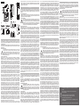
WIRING DIAGRAMS.
[1] Wind speed input, NPN output. [2] Wind speed input, PNP output. [3] Temperature input, Pt1=cell
and Pt2=air, 3 wires connections. [4] Temperature input, Pt1=cell and Pt2=air, 2 wires con nections.
[5] Irradiation input.
SAFETY PRECAUTIONS
Read carefully the instruction manual. If the instrument is used in a manner not spec-
ified by the producer, the protection provided by the instrument may be impaired.
Maintenance: make sure that the connections are correctly carried out in order to avoid
any malfunctioning or damage to the instrument. To keep the instrument clean, use a
slightly damp cloth; do not use any abrasives or solvents. We recommend to disconnect
the instrument before cleaning it.
TECHNICAL SPECIFICATIONS
Accuracy (@25°C ±5°C, R.H. ≥60%). Temperature See “Temperature input characteristics”.
Irradiation from 0 to 120mV: ±(0.5%RDG). Wind speed from 0 to 1000Hz: ±(0.01%RDG).
Temperature drift ≤200ppm/°C. Variables format instantaneous variables 4 DGT (Temperature, solar
irradiation and wind speed). Resolution 0.1°C/0.1°F; 1W/m
2
, 1W/ft
2
; 0.1m/s, 0.1ft/s. Temperature
probe inputs. Number of inputs 2. Temperature probe Pt100, Pt1000. Number of wires up to 3-wire
connection. Wire compensation up to 10Ω. Accuracy (Display + RS485) see table “Temperature input
characteristics” in the relevant data sheet. Temperature drift ±150ppm. Engineering unit selectable
°C or °F. Irradiation sensor inputs number of inputs 1. Range 0 to 120mVDC. Accuracy (@25°C
±5°C, R.H. ≤60%) ±(0.2%RDG+1DGT) 0% to 25% FS; (Display + RS485) ±(0.1%RDG+1DGT)
25% to 120% FS. Temperature drift ±150ppm. Scaling factor operating mode, dual scale: - Input:
programmable range from 0 to 999.9 (mVDC) - Display: program mable range from 0.000 to 9.999
(kW/m
2
, kW/ft
2
). Decimal point position fixed. Impedance > 30KΩ. Overload continuous 10VDC
(measurement available up to 1V on both display and com munication bus). For 1s 20VDC. Wind
speed sensor inputs number of inputs 1. Range 0 to 1000Hz max, duty cycle 50%. Accuracy @25°C
±5°C, R.H. ≤60%) (Display + RS485) ±(0.02%RDG+1DGT) 0% to 25% FS; ±(0.01%RDG+1DGT)
25% to 110% FS. Temperature drift ±150ppm. Scaling fac tor operating mode dual scale: - Input:
programmable range from 0 to 999.9 (Hz) - Display: pro grammable range from 0.1 to 299.9 (m/s,
ft/s). Decimal point position fixed. Operating input: 2.5V
peak
to 9V
peak
/5mA
peak
to 35mA
peak
, duty
cycle 50%; Impedence: 220Ω. Contact measuring voltage 10 to 50VDC. Contact measuring
current <10mA. Contact resistance ≤100Ω closed contact; ≥500kΩ open contact. Overload
continuous 10VDC (measurement available up to 1V on both display and communication bus)
for 1s 20VDC. Insulation, see “Insulation between inputs and out puts” in the relevant data sheet.
Operating temperature -25 to +55°C (-13°F to 131°F) (R.H. from 0 to < 90% non-condensing @
40°C). Storage temperature -30 to +70°C (-22°F to 140°F) (R.H. < 90% non-condensing @ 40°C).
Over voltage category Cat. III (IEC 60664, EN60664). For inputs from string: equivalent to Cat. I,
reinforced insulation. Dielectric strength 4000 VAC RMS for 1 minute. Noise rejection CMRR 100
dB, 45 to 65 Hz. EMC (Immunity) according to EN61000-6-2. Electrostatic discharges EN61000-4-2:
8kV air discharge, 4kV contact; Immunity to irradiated elec tromagnetic fields EN61000-4-3 : 10V/m
from 80 to 3000MHz; Immunity to Burst EN61000-4-4: 4kV on power lines, 2kV on signal lines;
Immunity to conducted disturbances EN61000-4-6: 10V from 150KHz to 80MHz; Surge EN61000-
4-5: 500V on power supply; 4kV on string inputs. EMC (Emission) according to EN61000-6-3. Radio
frequency suppression according to CISPR 22. Standard compliance safety IEC60664, IEC61010-1
EN60664, EN61010-1. Approvals CE, cULus Listed. Housing dimensions (WxHxD) 17.5 x 90 x 67
mm. Material Noryl, self-extinguishing: UL 94 V-0. Mounting DIN-rail. Protection degree Front IP40.
Screw terminals IP20. Connections Screw-type cable cross-section area 1.5 mm
2
max. Min./Max.
screws tightening torque: 0.4 Nm / 0.8 Nm. Screw terminal purposes 1.5 mm
2
3+3 screw terminals
used for two temperature probes 2 screw terminals used for wind speed sensor 2 screw terminals
used for solar irradiation sensor. Weight approx. 100 g (packing included). Power supply self-power
supplied through the communication bus. Power consumption ≤0,7W.
UL508 NOTES: Max. Surrounding Air of 40°C/104°F. Use 60/140°F or 75°C/167°F copper
(CU) conductor and wire size No. 30-12 AWG, stranded or solid for auxiliary and power supply
ENGLISH VMU-P
FUNZIONE LED RGB MULTICOLORE FRONTALE. Luce accesa fissa: il modulo è alimentato e
non c’è comunicazione sul bus ausiliario. Verde: alimentazione presente. Bianco: l’unità è abilita dal
modulo VMU-M per la lettura e visualizzazione dati. Giallo (luce lampeggiante): c’è comunicazione sul
bus asiliario.
COLLEGAMENTI ELETTRICI
[1] Ingresso velocità del vento, uscita NPN. [2] Ingresso velocità del vento, uscita PNP. [3] Ingresso
in temperatura, Pt1=cella e Pt2=aria, collegamento 3 fili. [4] Ingresso in temeperatura, Pt1=cella e
Pt2=aria, collegamento 2 fili. [5] Ingresso irraggiamento
NORME DI SICUREZZA
Leggere attentamente il manuale istruzioni. Qualora l’apparecchio venisse adoperato in
un modo non specificato dal costruttore, la protezione prevista dall’apparecchio potrebbe
essere compromessa. Manutenzione: assicurarsi che i collegamenti siano effettuati
correttamente al fine di evitare qualsiasi malfunzionamento o danneggiamento dello
strumento. Per mantenere pulito lo strumento usare un panno leggermente inumidito; non
usare abrasivi o solventi. Si consiglia di scollegare lo strumento prima di pulirlo.
CARATTERISTICHE TECNICHE
Precisione (@25°C ±5°C, U.R. ≤60%). Temperatura Vedere “Caratteristiche degli ingressi in
temperatura”. Irraggiamento da 0 a 120mV: ±(0,5%RDG). Wind speed da 0 a 1000Hz: ±(0,01%RDG).
Deriva termica ≤200ppm/°C. Formato delle variabili variabili istantanee 4 DGT (Temperatura,
irragiamento solare e velocità del vento). Risoluzione 0,1°C/0,1°F; 1W/m2, 1W/ft2; 0,1m/s, 0,1ft/s.
Ingressi sonde di temperatura. Numero ingressi 2. Sonde Pt100, Pt1000. Numero di fili: con nessione
fino a 3 fili. Compensazione fili fino a 10Ω. Precisione (Display + RS485) Vedere “carat teristiche
degli ingressi in temperatura” nel relativo data sheet. Deriva termica ±150ppm. Unità ingegneristica
selezionabile °C o °F. Isolamento vedere la tabella “Isolamento tra ingressi ed uscite”. Ingresso sensore
d’irraggiamento numero ingressi 1. Portata da 0 a 120mVCC. Precisione @25°C ±5°C, U.R. ≤60%
±(0,2%RDG+1DGT) 0% a 25% FS; (Display + RS485) ±(0,1%RDG+1DGT) 25% a 120% FS. Deriva
termica ±150ppm Fattore di scala Modo operativo duplice scala: - Ingresso: portata programmabile
da 0 a 999,9 (mVCC) - Display: portata program mabile da 0,000 a 9,999 (kW/m
2
, kW/ft
2
) Posizione
punto decimale fisso. Impedenza: > 30KΩ. Sovraccarico continuo 10VCC (misura disponibile fino a
1V su entrambi display e bus di comuni cazione). Per 1s 20VCC. Sensore per la velocità del vento.
Numero ingressi, 1. Portata da 0 a 1000Hz max, duty cycle 50%. Precisione @25°C ±5°C, U.R.
≤60% ±(0,02%RDG+1DGT) da 0% a 25% FS; (Display + RS485) ±(0,01%RDG+1DGT) da 25%
a 110% FS. Deriva termica ±150ppm. Fattore di scala modo operativo, Duplice duale: - Ingresso:
portata programmabile da 0 a 999.9 (Hz) - Visualizzata: portata programmabile da 0,1 a 299,9 (m/s,
ft/s). Posizione punto decimale fisso. Ingresso operativo: 2.5V
peak
to 9V
peak
/5mA
peak
to 35mA
peak
,
duty cycle 50%. Impedenza 220Ω. Tensione di lettura contatto da 10 a 50VCC. Corrente di lettura
contatto <10mA. Rersitenza del contatto ≤100Ω contatto chiuso; ≥500kΩ contatto aperto. Sovraccarico
Continuo 10VCC (misura disponibile fino a 1V sul display e sul bus di comunicazione). Per 1s 20VDC.
Isolamento, vedere “Isolamento tra ingressi ed uscite”. Temperatura di funzionamento. -25 to +55°C (da
-13°F a 131°F) (U.R. da 0 a < 90% senza condensa @ 40°C). Temperatura di immaggazzinamento -30
to +70°C (da -22°F a 140°F) (R.H. < 90% senza condensa @ 40°C). Categoria d’installazione Cat. III
(IEC 60664, EN60664) Per gl’ingressi di stringa: equivalente all Cat. I, isolamento rinforzato. Isolamento
(per 1 minuto) Vedere tabella “Isolamento tra ingressi ed uscite”. Rigidità dielettrica 4000 VAC RMS per
1 minuto. Reiezione CMRR 100 dB, da 45 a 65 Hz. EMC (Immunità) Secondo EN61000-6-2. Scariche
elettrostatiche EN61000-4-2: 8kV scarica in aria, 4kV contatto; Immunità ai campi elettromagnetici
irradianti EN61000-4-3: 10V/m da 80 a 3000MHz; Immunità ai transitori veloci EN61000-4-4: 4kV sulle
linee di potenza, 2kV su singole linee; Immunità ai radio disturbi condotti EN61000-4-6: 10V da 150KHz
a 80MHz; Immunità ad impulso EN61000-4-5: 500V sul l’alimentazione; 4kV sugli ingressi di stringa.
EMC (Emissioni) secondo EN61000-6-3, Emissioni in radiofrequenza secondo CISPR 22. Conformità
alle norme Sicurezza IEC60664, IEC61010-1 EN60664, EN61010-1. Approvazioni CE, cULus Listed.
Custodia: dimensioni 17,5 x 90 x 67 mm. Materiale Noryl, autoestinguenza: UL 94 V-0. Mountaggio
a guida DIN. Grado di protezione Frontale IP40. Connessioni IP20. Connessioni a vite. Sezione del
cavo 1,5 mm
2
max. Coppia serraggio viti Min./Max.: 0,4 Nm / 0,8 Nm. Utilizzo delle connessioni 1,5
mm
2
3+3 morsetti usati per due ingres si di temperatura 2 morsetti usati per il sensore della velocità
del vento 2 morsetti usati per il sensore di irraggiamento. Peso circa. 100 g (imballo compreso).
Alimentazione autoalimentato attraverso il bus locale. Autoconsumo ≤0,7W. Alimentazione da 12 a 28
VCC. Autoconsumo 1W.
DEUTSCH VMU-P
ITALIANO VMU-P
LED. Lumière fixe allumée: le module est alimenté et il n’y a pas de communication sur le bus auxiliaire.
Verte: l’alimentation est branchée. Blanche: l’unité est habilitée à la lecture et à l’affichage de données
par le module VMU-M. Jaune (lumière clignotante): la communication sur le bus auxiliaire fonctionne.
CONNEXIONS. [1] Entrée de vitesse du vent avec sortie NPN. [2] Entrée de vitesse du vent avec
sortie PNP. [3] Entrée température 1 et entrée 2, Pt1=cellule et Pt2=air, 3 fils de raccordement. [4] ntrée
température 1 et entrée 2, Pt1=cellule et Pt2=air, 2 fils de raccordement. [5] Entrée d’irradia tion.
PRÉCAUTIONS DE SECURITE
Lire attentivement le manuel de l’utilisateur. Si l’appareil est utilisé dans des condi-
tions différentes de celles spécifiées par le fabricant, le niveau de protection prévu par
l’instrument peut être compromis. Entretien: s’assurer que les connexions sont réali sées
correctement dans le but d’éviter toutes fautes ou endommagements de l’appareil. Pour
nettoyer l’instrument, utiliser un chiffon humide; ne pas utiliser d’abrasifs ou de solvants. Il
faut déconnecter le dispositif avant de procéder au nettoyage.
SPÉCIFICATIONS
Précision (@25°C ±5°C, H.R. ≤60%). Température Voir “Caractéristiques d’entrée de température”.
Irradiation de 0 à 120mV: ±(0.5%RDG). Vitesse du vent de 0 à 1000Hz: ±(0.01%RDG). Dérive de
température ≤200ppm/°C. Format de variables variables instantanées 4 DGT (Température, irradiation
solaire et vitesse du vent). Pouvoir de résolution 0.1°C/0.1°F; 1W/m2, 1W/ft2; 0.1m/s, 0.1ft/s. Entrées
de la sonde de température, nombre d’entrées 2. Sonde de température Pt100, Pt1000. Nombre de
câbles jusqu’à 3 fils de raccordement. Compensation du câble jusqu’à 10Ω. Précision (affichage +
RS485) voir “Caractéristiques d’entrée de température” dans la fiche tech nique. Dérive de température
±150ppm. Unité technique a choisir °C ou °F. Entrées capteur d’ir radiation, nombre d’entrées 1. Portée
d’émission 0 à 120mVCC. Précision (@25°C ±5°C, H.R.≤60%), ±(0.2%RDG+1DGT) 0% à 25%
FS; (Affichage + RS485) ±(0.1%RDG+1DGT) 25% to 120% FS. Dérive de température ±150ppm.
Facteur d’échelle mode de fonctionnement, echelle double: - Entrée: portée programmable de 0 à
999,9 (mVDC). - Affichage: portée programmable de 0,000 à 9,999 (kW/m
2,
kW/pied
2
). Position de
point décimal: fixe. Impédance > 30KΩ. Surcharge Continu 10VCC (mesurage disponible jusqu’à 1V
sur l’afficheur et le bus de communication) 20VCC. Pours 20VCC. Entrées du capteur de vitesse du
vent. Nombre d’entrées 1. Portée d’émis sion 0 à 1000Hz max, cycle de service 50%. Précision @25°C
±5°C, H.R. ≤60%), ±(0.02%RDG+1DGT) 0% à 25% FS; (Affichage + RS485), ±(0.01%RDG+1DGT)
25% à 110% FS. Dérive de température ±150ppm. Facteur d’échelle mode de fonctionnement
Echelle double: Entrée: portée programmable de 0 à 999,9 (Hz) - Afficheur: portée programmable
de 0,1 à 299,9 (m/s, pied/s). Position de point décimal: fixe. Entrée de fonctionnement: 2.5V
pic
à
9V
pic
/5mA
pic
à 35mA
pic
, cycle de service 50%. Impédance 220Ω. Contact mesurant la tension 10 à
50VCC. Contact mesurant le courant <10mA. Résistance de contact ≤100Ω Contact fermé; ≥500kΩ
contact ouvert. Surcharge Continu 10VCC (mesurage disponible jusqu’à 1V sur l’afficheur et le bus
de communication). Pours 20VCC. Isolation, voir le tableau “Isolation entre les entrées et les sorties”
dans la fiche technique. Température de fonctionnement -25 à +55°C (-13°F à 131°F) (H.R. de 0 à <
90% sans condensation @ 40°C). Température de stockage -30 à +70°C (-22°F à 140°F) (H.R. <
90% sans condensation @ 40°C). Catégorie de surtension Cat. III (IEC 60664, EN60664) Pour des
entrées de chaîne: équivalent à Cat. I, isolation renforcée. Rigidité diélectrique 4000 VCA RMS pour
1 minute. Émission de bruit CMRR 100 dB, 45 à 65 Hz. Compatibilité électromagnétique (immunité)
selon EN61000-6-2. Décharges électrostatiques EN61000-4-2: 8kV décharge d’air, 4kV contact;
Immunité aux champs électromagnétiques irradiés EN61000-4-3: 10V/m de 80 à 3000MHz; Immunité
aux rafales EN61000-4-4: 4kV sur les lignes électriques, 2kV sur les lignes de signal; Immunité aux
perturbations par conduction EN61000-4-6: 10V de 150KHz à 80MHz; surten sion EN61000-4-5: 500V
sur l’alimentation; 4kV sur les entrées de chaîne. Compatibilité électro magnétique (Emission) Selon
EN61000-6-3. Suppression de fréquence radio selon CISPR 22. Conformité aux normes sécurité
IEC60664, IEC61010-1, EN60664, EN61010-1. Approbations CE, cULus Listed. Boîtier dimensions
(LxHxD) 17.5 (+0.5 -0) x 90 x 67 mm. Material Noryl, auto-extin guible: UL 94 V-0. Montage Rail DIN.
Degré de protection avant IP40. Bornes à vis IP20. Connexions À vis. Aire de section de câble 1,5 mm2
max Coupe de serrage de vis min/max.: 0,4 Nm / 0,8 Nm. Buts de borne à vis 1.5 mm
2
3+3 Bornes
à vis utilisées pour les deux sondes de tem pérature 2 bornes à vis utilisées pour le capteur de vitesse
du vent 2 bornes à vis utilisées pour le capteur d’irradiation slaire. Poids Env. 100 g (emballage inclus).
Alimentation, auto alimentation fournie par le bus de communication. Consommation d’alimentation
≤0,7W.
FRANÇAIS VMU-P
NORMAS DE SEGURIDAD
Lea el manual y siga atentamente las instrucciones. Si se utiliza el equipo de manera
distinta de como indica el Fabricante, se puede dañar la protección de la que está provisto
el instrumento. Mantenimiento: Asegurarse de que las conexiones son correctas para
evitar un mal funcionamiento o daños en el instrumento. Para tener el instrumento limpio,
limpiar periódicamente la carcasa con un trapo un poco humedecido. No utili zar productos
abrasivos o disolventes. Desconectar el equipo antes de limpiarlo.
ESPECIFICACIONES
Desviación térmica, ≤200ppm/°C. Formato de variables, variables instantáneas 4 dígitos (Temperatura,
irradiancia solar y velocidad del viento). Resolución 0.1°C/0.1°F; 1W/m
2
, 0.1m/s. Entradas de la sonda
de temperaturas, número de entradas: 2. Sonda de temperatura Pt100, Pt1000. Número de hilos:
conexión de hasta 3 hilos. Compensación del cable: hasta 10Ω. Precisión (Display + RS485) véase la
tabla “Características de la entrada de temperatura” en la hoja de datos pertinente. Desviación térmica
±150ppm. Unidad de ingeniería seleccionable °C o °F. Entrada del sensor de irradiancia, número de
entradas: 1. Rango de 0 a 120mVCC. Precisión (@25°C ±5°C, H.R.≤60%) ±(0.2%lect.+1díg.) 0% a
25% f.e.; (Display + RS485) ±(0.1%lect.+1díg.) 25% a 120% f.e. Desviación térmica ±150ppm. Factor
de escala. Modo de funcionamiento: doble escala: - Rango programable de entrada de 0 a 999,9
(mVCC) - Display: rango programable de 0.000 a 9.999 (kW/m
2
). Posición del punto decimal: fija.
Impedancia > 30KΩ. Sobrecarga continua: 10VCC (medición disponible hasta 1V tanto en el display
como en el bus de comunicación). Para 1s 20VCC. Aislamiento: véase la tabla “Aislamiento entre
las entradas y el bus de comunicación”. Entradas del sensor de velocidad del viento. Número de
entradas 1. Rango de 0 a 1000Hz máx., ciclo de trabajo 50%. Precisión @25°C ±5°C, H.R. ≤60%)
±(0.02%lect.+1díg.) de 0% a 25% f.e.; (Display + RS485) ±(0.01%lect.+1díg.) de 25% a 110% f.e.
Desviación térmica ±150ppm. Factor de escala. Modo de funcionamiento doble escala: - rango
programable de entrada de 0 a 999.9 (Hz). - Display: rango programable de 0.1 a 299.9 (m/s). Posición
del punto decimal: fija. Entrada de funcionamiento: 2.5V
pico
a 9V
pico
/5mA
pico
a 35mA
pico
, ciclo de
trabajo 50%. Impedancia 220Ω.
Tensión de lectura del contacto de 10 a 50VCC. Intensidad de lectura del contacto <10mA. Resistencia
del contacto ≤100Ω contacto cerrado; ≥500kΩ contacto abierto. Sobrecarga continua 10VCC. Para1s
20VCC. Aislamiento, véase la tabla “Aislamiento entre las entradas y el bus de comunicación” en la
hoja de datos pertinente. Temperatura de funcionamiento -25 a +55°C (-13°F a 131°F) (H.R. de 0 a
< 90% sin condensación @ 40°C). Temperatura de almacenamiento -30 a +70°C (-22°F a 140°F)
(H.R. < 90% sin condensación @ 40°C). Categoría de sobretensión: Cat. III (IEC 60664, EN60664)
Para entradas de string: igual a la Cat. I, aislamiento reforzado. Aislamiento (durante 1 minuto). Véase
la tabla “Aislamiento entre las entradas y las salidas”. Rigidez dieléctrica 4000 VCA RMS durante
1 minuto. Rechazo al ruido. CMRR 100 dB, 45 a 65 Hz. Compatibilidad Electromagnética EMC
(Inmunidad). Según EN61000-6-2. Descargas electrostáticas EN61000-4-2: Descarga de aire 8kV,
contacto 4kV. Inmunidad a los campos electro magnéticos irradiados EN61000-4-3: 10V/m de 80 a
3000MHz; Inmunidad a transitorios rápidos EN61000-4-4:4kV en la líneas de alimentación, 2kV en las
líneas de señal; Inmunidad a las pertur baciones conducidas EN61000-4-6: 10V de 150KHz a 80MHz;
Sobretensión. EN61000-4-5: 500V en la alimentación; 4kV en las entradas de string. Compatibilidad
Electromagnética EMC (Emisión) Según EN61000-6-3. Eliminación de radiofrecuencia según CISPR
22. Conformidad al estándar. Seguridad IEC60664, IEC61010-1. EN60664, EN61010-1. Marca/
Homologaciones CE, cULus listed. Caja Dimensiones (Al.xAn.xP.) 17.5 x 90 x 67 mm. Material:
Noryl, autoextinguible: UL 94 V-0. Montaje. Carril DIN. Grado de protección. Frontal IP40. Terminales
de tornillo: IP20. Conexiones a tornillo. Sección del cable 1.5 mm
2
máx. Par de apriete mín./máx.:
0,4 Nm / 0,8 Nm. Terminales a tornillo 1.5 mm
2
,3+3 terminales a tornillo usados para dos sondas de
temperatura. 2 terminales a tornillo usados para el sensor de velocidad del viento. 2 terminales a tornillo
usa dos para la irradiancia solar. Peso Approx. 100 g (embalaje incluido). Alimentación autoalimenta-
ción suministrada a través del bus de comunicación. Consumo de energía ≤0,7W.
ESPAÑOL VMU-P
[1] [2]
[3]
[4]
[5]
VMU-P
G24
Join or divide the modules (M-S-O-P) ONLY when they’re NOT power
supplied.
Unire o separare i vari moduli (M-S-O-P) SOLO quando questi
NON sono alimentati.
Die Modules (M-S-O-P) dürfen nur voneinander getrennt
oder aneinandergereiht werden, wenn diese nicht an die
Spannungsversorgung angeschlossen sind.
Assembler ou dissocier les modules (M-S-O-P) UNIQUEMENT s’ils ne
sont pas alimentés.
Unir o separar los módulos (M-S-O-P) SÓLO cuando NO estén alimentados.
!
connections. Use 60/140°F or 75°C/167°F copper (CU) conductor and wire size No. 14-8 AWG,
stranded or solid for 600V-16A input connections. Terminal tightening torque of 0.4Nm for auxiliary
con nection. Terminal tightening torque of 1.1Nm for 600V input connections with AWG8 wire, 0.5 Nm
for smaller sizes. Open Type Device.
LED-LEUCHTE. Festlicht ON: Das Modul wird mit Strom versorgt und es besteht keine Kommunikation
an den Hilfsbus. Grün: Die Stromversorgung steht auf ON. Weiß: Die Einheit wird vom VMU-M Modul
zum Lesen und Anzeigen der Daten eingeschaltet. Gelb (Blinklicht): Die Kommunikation an den
Hilfsbus läuft.
ANSCHLÜSSE. [1] Windgeschwindigkeitseingang, PNP Ausgang. [2] Windgeschwindigkeits-
eingang, NPN Ausgang [3] Temperatureingang 1 und Eingang 2, Pt1=Zelle und Pt2=Luft, 3-adriger
Anschluss. [4] Temperatureingang 1 und Eingang 2, Pt1=Zelle und Pt2=Luft, 2-adriger Anschluss. [5]
Bestrahlungseingang.
SICHERHEITSBESTIMMUNGEN.
Die Betriebsanleitung aufmerksam lesen. Sollte das Gerät nicht gemäss der
Herstellerangaben verwendet werden, könnte der vom Gerät vorgesehene Schutz
beeinträchtigt werden. Wartung: Beachten Sie den korrekten Anschluss aller
Anschlussterminals um eine Beschädigung des Instrumentes zu vermeiden. Das Gerät
mit einem feuchten Tuch rei nigen; keine Scheuer- oder Lösemittel verwenden. Das Gerät
vor der Reinigung aus schalten.
TECHNISCHE DATEN
Genauigkeit (@25°C ±5°C, R.F. ≤60%). Temperatur siehe “Temperatureinganseigenschaften”
estrahlung von 0 bis 120mV: ±(0.5%RDG). Windgeschwindigkeit von 0 bis 1000Hz: ±(0.01%RDG)
Temperaturdrift ≤200ppm/°C. Messgrößenformat momentanmessgrößen 4 stellig (Temperatur,
Sonnenbestrahlung und Windgeschwindigkeit). Resolution 0.1°C/0.1°F; 1W/m2, 1W/ft2;
0.1m/s, 0.1ft/s. Temperatursondeneingänge Anzahl der Eingänge 2. Temperatursonde Pt100,
Pt1000. Anzahl der Adern Bis zu 3-adrigem Anschluss aderausgleich Bis zu 10Ω. Genauigkeit
(Display + RS485). Siehe Tabelle “Temperatureingangseigenschaften in dem entsprechenden
Datenblatt”. Temperaturdrift ±150ppm. Technische Einheit °C oder °F wählbar. Bestrahlung der
Sensoreingänge. Anzahl der Eingänge 1. Bereich 0 bis 120mVDC Genauigkeit (@25°C ±5°C,
R.F. ≤60%) ±(0.2%RDG+1DGT) 0% bis 25% FS; (Display + RS485) ±(0.1%RDG+1DGT) 25%
bis 120% FS. Temperaturdrift ±150ppm. Skalierungsfaktor Betriebsmodus Dualskala: Eingang:
Programmierbarer Bereich von 0 bis 999,9 (mVDC) - Display: Programmierbarer Bereich von 0,000
bis 9,999 (kW/m2, kW/ft2) Dezimalstellenposition: Fest. Impedanz: > 30KΩ. Überlast Dauer 10VDC
(Messung bis zu 1V auf Display- und Kommunikationsbus verfügbar). Für 1s 20VDC. Eingänge für
Windgeschwindigkeitssensor, Anzahl der Eingänge 1. Bereich 0 bis max 1000Hz, Arbeitszyklus 50%.
Genauigkeit @25°C ±5°C, R.H. ≤60%) ±(0.02%RDG+1DGT) 0% bis 25% FS; (Display + RS485)
±(0.01%RDG+1DGT) 25% bis 110% FS. Temperaturdrift ±150ppm. Skalierungsfaktor Betriebsmodus
Dualskala: - Eingang: Programmierbarer Bereich von 0 bis 999,9 (Hz) - Display: Programmierbarer
Bereich von 0,1 bis 299,9 (m/s, ft/s). Dezimalstellenposition: Betriebseingang: 2.5V
Spitze
bis 9V
Spitze
/ 5mA
Spitze
bis 35mA
Spitze
, Arbeitszyklus 50%. Impedanz 220Ω. Kontakt für Spannungsmessung10
bis 50VDC. Kontakt für Strommessung <10mA. Kontaktwiderstand ≤100Ω geschlossener Kontakt;
≥500kΩ offener Kontakt. Überlast kontinuierlich 10VDC (Messung bis zu 1V an Display- und
Kommunikationsbus verfügbar). Für 1s 20VDC. Isolation, siehe Tabelle “Isolation zwischen Ein- und
Ausgängen” in dem entsprechenden Datenblatt. Betriebstemperatur -25 bis +55°C (-13°F bis 131°F)
(R.F. von 0 bis < 90% nicht kon densierend @ 40°C). Speichertemperatur -30 bis +70°C (-22°F bis
140°F) (R.F. < 90% nicht kon densierend @ 40°C). Überspannungs klasse Kl. III (IEC 60664, EN60664)
Für Eingänge vom String: entspricht Kl. I, verstärkte Isolierung. Dielektrische Stärke 4000 V AC RMS
für 1 Minute. Lärmrückweisung Gleichtaktunterdrückungs-verhältnis 100 dB, 45 bis 65 Hz. EMC
(Immunität) Gemäß EN61000-6-2. Elektrostatische Entladungen EN61000-4-2: 8kV Luftentladung,
4kV Kontakt; Immunität bei bestrahlten elektromagnetischen Feldern EN61000-4-3: 10V/m von 80
bis 3000MHz; Immunität bei Bersten EN61000-4-4: 4kV an Stromleitungen, 2kV an Signalleitungen;
Immunität bei Leitungsstörungen EN61000-4-6: 10V von 150KHz bis 80MHz; Momentanüberstrom
EN61000 4-5: 500V an Stromversorgung; 4kV an Stringeingängen. EMC (Emission) Gemäß EN61000-
6-3. Funkfrequenzunterbrechung Gemäß CISPR 22. Standardkonformität Sicherheit IEC60664,
IEC61010-1 EN60664, EN61010-1. Zulassungen CE, cULus Listed. Gehäuse abmessungen (LxHxT)
17.5 (+0.5 -0) x 90 x 67 mm. Material Noryl, selbstlöschend: UL 94 V-0 Montage DIN-Rail. Schutzgrad
Vorderseite IP40 Schraubenklemmen IP20. Anschlüsse Schraubentyp Kabelquerschnittsbereich 1,5
mm2 max Min./Max. Schraubenanzugsmoment: 0,4 Nm / 0,8 Nm. Schraubenendverschlusszwecke
1.5 mm
2
3+3 Schraubenendverschlüsse für zwei Temperatursonden 2 Schraubenendverschlüsse für
Windgeschwindigkeitssensor 2 Schraubenendverschlüsse für Sonnenbestrahlungssensor. Gewicht
Ca. 100 g (inkl. Verpackung). Stromversorgung Durch Kommunikationsbus eigenstromversorgt.
Stromverbrauch ≤0,7W.
LED RGB. ON encendido fijo: el módulo está alimentado. Verde: la alimentación está activada. Blanco:
la unidad ha sido habilitada por el módulo VMU-M para leer y visualizar los datos. nCONEXIONES. [1]
Entrada de la veloc. del viento, salida NPN. [2] Entrada de la veloc. del viento, salida PNP. [3] Entrada
de Temperatura 1 y entr. 2, Pt1=célula y Pt2=aire, conexión 3 hilos. [4] Entrada de Temperatura 1 y entr.
2, Pt1=célula y Pt2=aire, conexión 2 hilos. [5] Entrada de irra diancia.
-
 1
1
-
 2
2


CARLO GAVAZZI VMUSAV30XSXX Guida d'installazione
- Tipo
- Guida d'installazione
- Questo manuale è adatto anche per
in altre lingue
Documenti correlati
-
CARLO GAVAZZI VMUM4AS1T2EM Guida d'installazione
-
-
CARLO GAVAZZI VMUP2TCWXSEM Guida d'installazione
-
-
-
-
-
-
-
Altri documenti
-
Gossen MetraWatt U180A Istruzioni per l'uso
-
-
CAME 67400011 Guida d'installazione
-
Ascon tecnologic DX Guida d'installazione
-
-
Smeg S45MFX Manuale utente
-
-
Bticino F3N110 Istruzioni per l'uso
-
Danfoss Discharge gas temperature sensor replacement on PSH051-064-077 Guida d'installazione
-
Orbis Viaris Solar Three Phase Istruzioni per l'uso