
1
PSI-5500TL
PSI-7000TL
PSI-8500TL
PSI-10000TL
EN / IT
TRIPHASE INVERTER
INVERTER TRIFASE

2

1
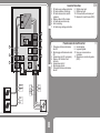
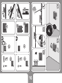
About this Installation Guide .......... 2
Safety Symbols............................... 3
General Safety Requirements ........ 4
Intended Use .................................. 5
Inverter Function............................. 8
Labels and Markings on
the Inverter ..................................... 9
Connections on the Inverter ......... 10
User Interface ...............................11
Unpacking..................................... 12
Mounting the Inverter.................... 14
AC- and DC-Connection ............... 17
Starting the Inverter ...................... 21
Commissioning ............................. 22
Inverter Conguration ................... 24
Opening the Inverter ..................... 25
SD Card / Digital Input /
Digital Output ................................ 26
Technical Data .............................. 30
Table of Contents
Indice
EN
IT
Informazioni sulle presenti
istruzioni per l’installazione ............. 2
Simboli di sicurezza ........................ 3
Avvertenze generali di sicurezza .... 4
Uso conforme ................................. 5
Funzionamento ............................... 8
Avvertenze e simboli sull’inverter ... 9
Collegamenti................................. 10
Interfaccia utente ......................... 11
Disimballaggio .............................. 12
Montaggio dell’inverter ................. 14
Collegamento AC e DC ................ 17
Avvio dell’inverter ......................... 21
Messa in funzione......................... 23
Congurazione ............................. 24
Come aprire l’inverter ................... 25
Scheda SD / Ingresso digitale /
Uscita digitale ............................... 26
Dati tecnici .................................... 31
1

2
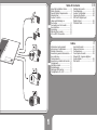
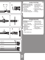
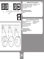
This installation guide describes the
safe installation of the inverters listed
on the left.
Target group:
Qualied technicians
Terms:
Installer Qualied technician
in charge of the
installation
Supplier Company the product
was purchased from
Inverter PV-inverter described
in this installation guide
About this Installation Guide
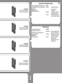
PSI-5500TL
Max. DC-Power 5750 W
Max. AC-Power 5500 W
EN
PSI-7000TL
Max. DC-Power 7400 W
Max. AC-Power 7000 W
PSI-8500TL
Max. DC-Power 8900 W
Max. AC-Power 8500 W
PSI-10000TL
Max. DC-Power 10500 W
Max. AC-Power 10000 W
Le presenti istruzioni per
l’installazione descrivono
l’installazione sicura degli inverter
elencati a sinistra.
Destinatari:
Tecnici qualicati
Termini:
Installatore Tecnico qualicato che
esegue l’installazione.
Fornitore Azienda da cui è stato
acquistato il prodotto.
Inverter Inverter fotovoltaico
descritto nelle
presenti istruzioni per
l’installazione.
Informazioni
IT

3
1
2
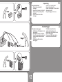
Life threatening voltages are
processed inside the inverter.
Hazardous situations that can lead to
death or serious injuries are indicated
with the “WARNING” symbol (1) on
the left.
Hazardous situations that can result in
damage of the inverter are indicated
with the “CAUTION” symbol (2) on the
left.
Countermeasures that must
be taken in order to avoid the
hazardous situation are indicated with
an arrow:
Î “This is an example how to avoid a
hazardous situation.”
Safety Symbols
Nell’inverter sono presenti tensioni
mortali.
Situazioni pericolose che possono
causare morte o lesioni gravi
sono contrassegnate dal simbolo
“AVVERTENZA” (1) a sinistra.
Situazioni pericolose che possono
danneggiare l’inverter sono
contrassegnate dal simbolo
“CAUTELA” (2) a sinistra.
Contromisure per prevenire
la situazione pericolosa sono
indicate con una freccia:
Î “Questo è un esempio di come
prevenire una situazione
pericolosa.”
Simboli di sicurezza
EN
IT

4
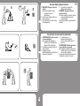
1. WARNING! Danger of electric
shock!
Î Read Installation Guide
carefully. Follow all
instructions.
2. Contact your supplier when you
have questions.
3. Wear safety shoes when lifting
and transporting.
4. 2 people are required for
lifting and transporting.
WARNING! Danger of electric
shock and re!
Î Never modify the inverter except
instructed otherwise by the
manufactured.
Keep this installation guide near the
inverter!
General Safety Requirements
EN
1. AVVERTENZA! Pericolo dovuto
a scossa elettrica!
Î Leggere attentamente le
istruzioni per l’installazione.
Seguire tutte le istruzioni.
2. Contattare il proprio fornitore in
caso di dubbi.
3. Indossare scarpe
antinfortunistiche se si sposta o si
trasporta il dispositivo.
4. Il sollevamento e il
trasporto del dispositivo
devono essere effettuati da 2
persone.
AVVERTENZA! Pericolo dovuto a
scossa elettrica e incendi!
Î Qualsiasi modica dell’inverter è
vietata salvo in caso di istruzioni
ricevute dal produttore.
Conservare le presenti istruzioni per
l’installazione vicino all’inverter.
Avvertenze di sicurezza fondamentali
IT

5
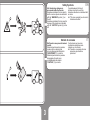
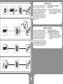
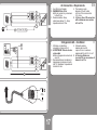
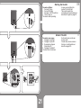
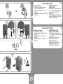
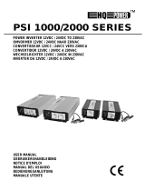
The inverter (1) converts DC-power
from the PV-generator (2) to AC-
power. The AC-power is fed into the
grid (3). In case of a grid failure: The
inverter automatically disconnects
(4) from the grid. The inverter
automatically reconnects when the
grid is restored. The inverter can
only be used for DC-power from PV-
generators (5).
CAUTION! Risk of damaging
the inverter!
Î Do not connect other DC-power
sources (6) such as wind power
systems, hydroelectric generators,
fuel cells or batteries.
Intended Use
L’inverter (1) trasforma la potenza
DC del generatore fotovoltaico (2)
in potenza AC. La potenza AC viene
immessa nella rete pubblica (3).
In caso di guasto di rete: L’inverter
si scollega (4) automaticamente
dalla rete. L’inverter si ricollega
automaticamente alla rete quando
essa viene ripristinata. L’inverter può
essere utilizzato solo per la potenza
DC dei generatori fotovoltaici (5).
CAUTELA! Pericolo di
danneggiamento dell’inverter!
Î Altre fonti di potenza DC (6)
come ad es. centrali eoliche e
idroelettriche, celle a combustibile
o batterie non devono essere
collegate.
Utilizzo conforme
EN
IT

6
1. WARNING! Risk of electric
shock! The PV-panels emit a
dangerous DC-voltage when
exposed to sunlight.
2. The inverter is not
equipped with an internal
isolation transformer
3. Local regulations and standards
can require that an additional
isolation transformer. Contact
your utility operator if you have
questions.
Electrical Safety
EN
1. AVVERTENZA! Pericolo di
scossa elettrica! I moduli
fotovoltaici generano tensione DC
pericolosa quando splende il sole.
2. L’inverter dispone di un
trasformatore di separazione.
3. Le disposizioni e le normative
in vigore possono prevedere
l’impiego di un trasformatore.
Chiedere al proprio gestore di rete.
Sicurezza elettrica
IT

7
1. Local regulations and standards
can require that current-breakers
are installed on the DC-side.
Contact your utility operator if you
have questions.
2. The inverter is equipped
with an integrated RCMU
Type B (tested according to EN
62109-2 / IEC 60755). If local
regulations and standards require
an external RCD/RCM, a RCD/
RCM Type A is sufcient.
DC-Disconnect / RCD
1. Le disposizioni e le normative
in vigore possono prevedere
l’impiego di sezionatori dal lato DC.
Chiedere al proprio gestore di rete.
2. L’inverter è dotato di una RCMU
integrata del tipo B (certicata
secondo EN 62109-2 / IEC 60755).
Nel caso in cui le disposizioni
e le normative locali richiedano
l’installazione di un RCD/RCM
esterno, è sufciente un RCD/RCM
di tipo A.
Dispositivo di separazione DC / RCB
EN
IT

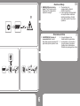
8
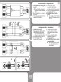
SD
5
DC2
-
DC2+
DC1+
DC1
-
L1
L2
L3
N
PE
6
7
8
9
4
3
2
1
10
11
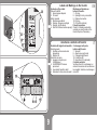
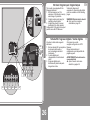
1. DC-side surge voltage protection
2. DC-side insulation monitoring
3. DC-side disconnection switch
(optional)
4. Display, status LEDs, buttons
5. AC-side disconnection relay
6. Grid monitoring
7. AC-side surge voltage protection
8. Digital output port
9. Digital input port
10. Communication extension port
11. Residual Current Device (RCD)
Inverter Function
EN
1. Protezione dalla sovratensione
lato DC
2. Monitoraggio dell’isolamento lato
DC
3. Sezionatore lato DC (opzionale)
4. Display, LED di stato, tasti
funzione
5. Sezionatore lato AC
6. Monitoraggio di rete
7. Protezione dalla sovratensione
lato AC
8. Uscita digitale
9. Ingresso digitale
10. Vano per comunicazione
opzionale
11. Misurazione corrente di guasto
(RCD)
Funzionamento dell’inverter
IT

9
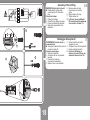
Symbols on Type Label:
General Symbols
1. Ensure proper disposal
2. CE-mark
Safety Symbols
3. Read documentation!
4. Warning: Dangerous voltage!
5. Warning: Hot Surfaces!
6. Wait for 5 Minutes before opening!
Markings and Symbols on
bottom of Inverter:
7. AC-plug
8. Opening for relay connection
9. Ethernet connection
10. DC-plug
11. DC-switch (optional)
Periodic Inspection:
Check if all markings and safety
symbols are clearly visible on the
inverter. Replace if necessary.
Labels and Markings on the Inverter
Simboli sulla targhetta del modello:
Simboli generali
1. Smaltire conformemente alle
disposizioni
2. Marchio CE
Simboli di sicurezza
3. Leggere le istruzioni per
l’installazione!
4. AVVERTENZA! Tensione
pericolosa!
5. Avvertenza! Superci calde!
6. Attendere 5 minuti prima di aprire!
Contrassegni sulla parte
inferiore dell’inverter:
7. Spina AC
8. Apertura per uscita relè
9. Collegamento Ethernet
10. Connettore DC
11. Interruttore DC (opzionale)
Controllo periodico:
Vericare che tutti i contrassegni e i
simboli di sicurezza sull’inverter siano
ben leggibili. Sostituire i contrassegni
mancanti.
Avvertenze e simboli sull’inverter
EN
IT

10
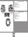
1. DC-switch (optional)
2. DC-plugs
3. Ethernet connector
4. Cable gland for digital input and
digital output
5. Valve for pressure discharge
6. AC-plug
7. Optional communication port
EN
Connections on the Inverter
1
7
3
5
6
2
4
1. Interruttore DC (opzionale)
2. Connettore DC
3. Presa Ethernet
4. Apertura per ingressi digitali e
uscite digitali
5. Valvola per compensazione della
pressione
6. Spina AC
7. Vano per comunicazione
opzionale
Collegamenti dell’inverter
IT

11
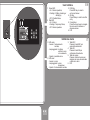
1
2
3
4
5
6
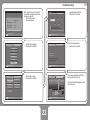
1. Green LED:
- On = Normal operation;
- Flashing = Waiting, checking or
starting up;
- Off = Possible failure.
2. Red LED
- On = Failure;
- Flashing = Temporary failure;
- Off = Normal operation.
3. ESC-Key
Press ESC-key in order to
exit current screen
4. OK-Key
Press OK-key in order to conrm
entry.
5. Cursor-Keys:
Press the cursor keys to navigate
the menu and to increase or
decrease values.
6. LCD
User Interface
EN
1. LED verde
- Acceso = funzionamento
normale;
- Lampeggiante = in attesa,
verica in corso
o in avviamento,
- Spento = possibile errore
2. LED rosso
- Acceso = errore
- Lampeggiante = errore
temporaneo
- Spento = funzionamento normale
3. Tasto ESC
Premere il tasto ESC per
uscire dalla schermata.
4. Tasto OK
Premere il tasto OK per
confermare l’inserimento.
5. Tasti del cursore:
Premere i tasti del cursore per
navigare nel menu ed aumentare
o diminuire i valori.
6. LCD
Interfaccia utente
IT

12
Proceed as follows:
• Check the packaging for
damages.
• Unpack the inverter and check if
the items of the packing list are
included.
• Check the items for visible
damages.
Contact your supplier when
items are missing or the
inverter is damaged. Do not install a
damaged inverter.
Keep packaging for later use.
Unpacking
EN
Procedere come segue:
• Vericare che l’imballaggio non sia
danneggiato.
• Disimballare l’inverter e vericare
che tutti i componenti elencati come
contenuto della confezione siano
presenti.
• Vericare che il tutto non sia
danneggiato.
Contattare il proprio fornitore
qualora manchi qualcosa o in
caso di danni. Non utilizzare mai un
inverter danneggiato.
Conservare l’imballaggio per un
eventuale utilizzo successivo.
Disimballaggio
IT

13
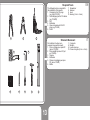
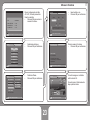
The following tools are required for
the installation of the inverter:
1. Crimping tool for DC-plugs
(e.g. type PV-CZM)
2. Cable stripping tool for DC-cables
(e.g. PV-AZM)
3. Drill
4. Multimeter
5. Open-end spanner kit for DC-
plugs (e.g. PV-MS)
6. Pencil
7. Screwdriver
8. Hammer
9. Level
10. Hex key (2 mm + 4 mm)
EN
Required Tools
1 2 3
7 865
4 10
9
Per installare l’inverter sono
necessari i seguenti strumenti:
1. Pinza a crimpare per spina DC
(ad es. PV-CZM)
2. Pinza spelali per cavo DC (ad
es. PV-AZM)
3. Trapano
4. Multimetro
5. Chiave di montaggio per spina
DC (ad es. PV-MS)
6. Matita
7. Cacciavite
8. Martello
9. Livella ad acqua
10. Chiave a brugola (2 mm + 4 mm)
Strumenti Necessari
IT

14
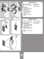
Requirements for the installation
location are specied on the following
pages.
Proceed as follows:
1. On plasterboard walls: Use center
holes. Screw wall mounting
bracket to wall stud.
2. On massive walls: Use outside
holes. Screw wall mounting
bracket to wall.
3. Hang inverter on wall mounting
bracket.
4. Check correct position.
5. Optional: Secure the
inverter with a padlock.
EN
Mounting the Inverter
Le condizioni del luogo di montaggio
sono riportate nelle pagine seguenti.
Procedere come segue:
1. Su lastre di cartongesso: utilizzare
i fori centrali. Avvitare il supporto a
parete sulla listellatura.
2. Su pareti massicce: utilizzare i fori
esterni. Avvitare il supporto sulla
parete.
3. Appendere l’inverter al supporto a
parete.
4. Vericare la corretta sede.
5. Opzionale: proteggere da
furti con un lucchetto.
Montaggio dell’inverter
IT

15
Gerald von Stein-Salisbury
Gerald von Stein-Salisbury
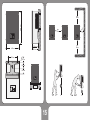
58.0 cm
44.0 cm
21.0 cm
22.5 cm
31.0 cm
24 kg
3.5 cm
10.0 cm
10.0 cm
min.
50 cm
min.
50 cm
min.
50 cm
min.
50 cm

16

17
L1
L2
L3
N
PE
L1
L2
L3
N
PE
1
2
max.
22 mm
4
3
FR: 6 mm Cu PE
2
5
1. Use 25 A circuit breaker.
2. WARNING! Risk of re!
Î Do not connect any consumers
to the AC-line.
3. Recommendation: Keep
cable losses below 1 %. Keep
impedance below 2 Ohm.
4. The maximum outer
diameter of the AC-cable
is 22 mm. Wire cross section
2.5 - 6 mm
2
5. In France: Use a PE-connection
with a minimum cross section
of 6 mm
2
Cu.
EN
AC-Connection - Requirements
1. Utilizzare un interruttore
automatico di linea da 25 A.
2. AVVERTENZA! Pericolo dovuto
ad incendio!
Î Non collegare alcuna utenza al
cavo AC.
3. Raccomandazione: mantenere la
dispersione di potenza al di sotto
dell’1%. Mantenere l’impedenza al
di sotto di 2 ohm.
4. Il diametro esterno
massimo del cavo AC
è pari a 22 mm. La sezione
massima del lo è di 2,5 - 4 mm
2
5. In Francia: utilizzare un
raccordo PE con una sezione di
almeno 6 mm
2
Cu.
Collegamento AC – Condizioni
IT

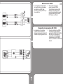
18
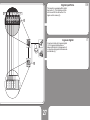
WARNING! Risk of electric shock!
Î Deactivate AC-voltage when
connecting the AC-connection
plug.
Proceed as follows:
1. Disconnect voltage.
2. Check that no voltage is present.
3. Prevent accidental reconnection
4. Strip cable as specied in the
illustration.
5. Remove swivel nut and
shove swivel nut over the
cable.
6. Attach wires to AC-plug.
7. Tighten swivel nut.
8. In France: Use an additional
PE-connection with a minimum
cross section of 6 mm
2
Cu.
Assembly of the AC-Plug
L1
L2
L3
N
PE
1
2
0 V ?
3
A
B
4
5
6
7
8
AVVERTENZA! Pericolo dovuto a
scossa elettrica!
Î Scollegare la tensione AC prima di
montare la spina AC.
Procedere come segue:
1. Staccare la tensione.
2. Accertarsi che non sia presente
tensione.
3. Prevenire ed evitare la
riaccensione accidentale
4. Spelare il cavo come descritto.
5. Svitare i dadi dei raccordi e
spingere sul cavo.
6. Collegare il cavo AC alla spina AC.
7. Serrare i dadi dei raccordi.
8. In Francia: Utilizzare un
ulteriore raccordo PE con una
sezione di almeno 6 mm
2
Cu.
Montaggio della spina AC
EN
IT
La pagina si sta caricando...
La pagina si sta caricando...
La pagina si sta caricando...
La pagina si sta caricando...
La pagina si sta caricando...
La pagina si sta caricando...
La pagina si sta caricando...
La pagina si sta caricando...
La pagina si sta caricando...
La pagina si sta caricando...
La pagina si sta caricando...
La pagina si sta caricando...
La pagina si sta caricando...
La pagina si sta caricando...
-
 1
1
-
 2
2
-
 3
3
-
 4
4
-
 5
5
-
 6
6
-
 7
7
-
 8
8
-
 9
9
-
 10
10
-
 11
11
-
 12
12
-
 13
13
-
 14
14
-
 15
15
-
 16
16
-
 17
17
-
 18
18
-
 19
19
-
 20
20
-
 21
21
-
 22
22
-
 23
23
-
 24
24
-
 25
25
-
 26
26
-
 27
27
-
 28
28
-
 29
29
-
 30
30
-
 31
31
-
 32
32
-
 33
33
-
 34
34


Peimar PSI-10000TL Guida d'installazione
- Tipo
- Guida d'installazione
- Questo manuale è adatto anche per
in altre lingue
Altri documenti
-
Mitsubishi Electric PV-S4600-IT Scheda dati
-
 HQ Power PSI1000 Manuale utente
-
Vetus Inverter type IV Manuale utente
-
Dometic PerfectPower PP1000 Istruzioni per l'uso
-
 Eltek Valere Theia He-t Guida d'installazione
-
-
-
-
-
Belkin F5C412EB140W Manuale utente

