Fracarro UTP-4RX12 Scheda dati
- Categoria
- Distributori video
- Tipo
- Scheda dati
Questo manuale è adatto anche per

receiver
EGNALE
12V
CH
1
S
BLU
+
BLU-BIANCO
+
-
+
-
MARRONE
+
MARRONE-BIANCO
CH
2
VERDE
+
VERDE
-
BIANCO
ARANCIO
+
ARANCIO
-
BIANCO
C
A
VO
C
A
T5
SIGNAL
12V
CH
1
BLUE
+
BLUE-WHITE
+
-
+
-
BROWN
+
BROWN-WHITE
CH
2
GREEN
+
GREEN
-
WHITE
ORANGE
+
ORANGE
-
WHITE
C
A
T5
CABLE
Avvertenze
ITALIANO
Warning
ENGLISH
>
Prima dell’uso leggere con attenzione il presente manuale.
>
Questo prodotto non va mai collegato ad apparecchiature diverse da
quelle specificate nel presente manuale.
>
Non cortocircuitare il connettore di uscita 12Vdc
Caratteristiche tecniche
>
Please read the directions carefully before using the tool.
>
Do not connect this tool to any other device not specifically
described in this handbook.
>
Do not short-circuit the 12Vdc output connector.
Technical data
Video input
Video output
Nr 1 BNC - 1 Vpp 75 ohm
UTP/FTP CAT5/6 AWG24
Video input
Video output
Nr 1 BNC - 1 Vpp 75 ohm
UTP/FTP CAT5/6 AWG24
Alimentazione telecamera
Spina DC
Camera power supply
DC plug
mod.
UTP-TX12
Distanza di trasmissione
Potenza
Temperatura esercizio
Grado di protezione
Dimensioni (LxHxP)
Peso
max 80 metri
0 W
-10 °C ÷ +40 °C
IP50
40x22x50 mm
27 g
Transmission distance
Power
Operating temperature
IP Protection
Dimensions (LxHxD)
Weight
max 80 m
0 W
-10 °C ÷ +40 °C
IP50
40x22x50 mm
27 g
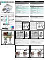
Impiego
UTP-TX12 è un trasmettitore di segnale video 1 canale che allo stesso
tempo fornisce 12Vdc alla telecamera se abbinato ad uno dei
seguenti ricevitori: UTP-4RX12
Con un solo cavo CAT5 è possibile collegare il segnale video e
l'alimentazione a due telecamere, permettendo di evitare
l'installazione di alimentatori dedicati ad ogni telecamera (fig.1)
Utilities
UTP-TX12 is a video signal 1 channel transmitter which also
supplies the camera with the DC12V if combined with one of
the following receivers: UTP-4RX12
This allows an easier and faster cable tracing and prevents from the
installation of one dedicated power supply for each camera
(picture1).
1
CH
1
CH
2
A
B
C
D
E
F
G
H
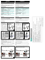
Istruzioni per l'uso
>
Aprire il contenitore allargando
le linguette di aggancio sulla
parte inferiore (fig.3)
>
Sguainare il cavo CAT5 per
20mm circa senza tagliare i
conduttori interni (fig. 6).
>
Tagliare i conduttori del colore
relativo alla telecamera da
collegare, seguendo le
indicazioni sull'etichett a
all'interno del contenitore e
facendo attenzione alla
polarità (fig.4)
Parte inf.
3
Instruction
>
Open the case by releasing
the hooking tongues on the
bottom (picture 3).
>
Remove the protecting
sheath of CAT5 cable for
about 20mm without cutting
the internal conductors.
>
Cut the conductors which
colours correspond to the
camera that has to be
connected following the
instructions on the label
inside the UTO-TX12 and
taking care of right polarity
(picture 4).
Bottom
3
CLOSED OPEN
CACCIAVITE
2,5 x 0,4 mm
SCREWDRIVER
2,5 x 0,4 mm
CAT5
CAT5
CHIUSO
APERTO
CLOSED
OPEN
ETICHETTA INTERNA
CONNETTORE
4
5
Inner label
CONNECTOR
4 5
IN
2
VIDEO
OUT 12Vdc
(cable provided)
>
Spellare i conduttori circa 5mm ed inserirli nel connettore. Chiudere il
morsetto spostando la slitta in posizione CHIUSO (fig 2 e 5) con
l'aiuto di un cacciavite.
>
Posizionare il cavo CAT5 in modo che possa uscire dai fori laterali del
contenitore, come mostrato in fig.6.
>
Chiudere il contenitore ed eventualmente fissarlo al muro o alla
scatola stagna con una vite.
>
Collegare l'alimentazione della telecamera allo spinotto 12Vdc del
UTP-TX12.
>
Accendere il ricevitore e verificare l'accensione del LED sul UTP-TX12.
>
Collegare il BNC all'uscita video della telecamera.
>
Rip the conductors off for about 5mm and insert them in the
connector. Close the terminal changing the slide connector to OFF
position by means of a screwdriver (pictures 2 and 5).
>
Place CAT5 cable so that it could come out from the side holes of
the case (see picture 6).
>
Close the UTP-TX12 case and place it where you need (fixed to wall or
to a watertight box with a screw).
>
Connect the camera power supply to UTP-TX12 12V dc plug.
>
Switch on the receiver and check if the UTP-TX12 LED is on.
>
Connect the BNC connector to the camera video output.
Preparazione cavo CAT5 e connessioni. Preparation CAT5 cable and connections.
20mm
UTP-TX12 UTP-TX12
ricevitore
20mm
UTP-TX12 UTP-TX12
Telecamera 1
Telecamera 2
6
Camera 1
Camera 2
6
La pagina sta caricando ...
-
 1
1
-
 2
2


Fracarro UTP-4RX12 Scheda dati
- Categoria
- Distributori video
- Tipo
- Scheda dati
- Questo manuale è adatto anche per
in altre lingue
- English: Fracarro UTP-4RX12 Datasheet
- français: Fracarro UTP-4RX12 Fiche technique
- español: Fracarro UTP-4RX12 Ficha de datos