
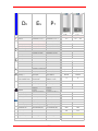
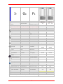
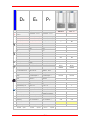
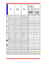
IT
GB
FR
DE
ES
PT
ADN 252
ADN 253
ADN 254
ADN 255
ADN 256
DESIGN SERIES
10T
10TR
14T
6T
2/1
10T 2/1
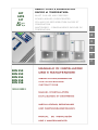
ABBATTITORI e SURGELATORI
RAPIDI di TEMPERATURA
BLAST C HILLER AND FREEZERS
SCHNELLKÜHLER CHOCKFROSTER
CELLULES DE REFRIGERATION RAPI DE ET
CON GELATION
ABATI DORE S – CONGELADORES R APIDOS DE
TEMPERATURA

Il costruttore si riserva il diritto di modificare senza preavviso le caratteristiche delle apparecchiature presentate in
questa pubblicazione.
The manufacturer reserves the right to modify the appliances presented in this publication without notice.
Le fabricant se réserve le droit de modifier sans préavis les caractéristiques des appareil présentés dans cette
publication.
Der Hersteller behält sich das Recht vor, die in dieser Broschüre vorgelegten Geräte ohne Voranzeige zuändern.
El constructor se reserva el derecho de modificar sin previo aviso las características de los equipos presentados
en esta publicación.
O fabricante reserva-se o direito de modificar sem aviso prévio as características dos aparelhos apresentados
nesta publicação.
PT
ES
DE
FR
GB
IT

1
ENGLISH
GB
1. INDEX
1. INDEX............................................................................................................................................1
2. ANALYTICAL INDEX.....................................................................................................................2
3. REGULATIONS AND GENERAL INSTRUCTIONS........................................................................3
3.1. General information..............................................................................................................3
3.2. Warranty..............................................................................................................................3
3.3. Replacement of Parts...........................................................................................................3
3.4. Description of the Appliance.................................................................................................4
3.5. Features Plate......................................................................................................................5
4. SAFETY.........................................................................................................................................5
4.1. Safety Devices.....................................................................................................................6
5. USE AND FUNCTIONING..............................................................................................................7
5.1. Description of the Functioning Cycles...................................................................................7
5.2. Description of the Controls...................................................................................................8
5.3. Functionality.........................................................................................................................9
5.4. Recommendations for Use.................................................................................................13
6. CLEANING AND MAINTENANCE................................................................................................15
6.1. Recommendations for Cleaning and Maintenance..............................................................15
6.2. Routine Maintenance..........................................................................................................15
6.3. Extraordinary Maintenance 10T and 14T............................................................................15
6.4. Extraordinary Maintenance 10TR.......................................................................................17
6.5. Extraordinary Maintenance 6T 2/1......................................................................................19
6.6. Extraordinary Maintenance 10T 2/1....................................................................................21
7. TROUBLESHOOTING.................................................................................................................24
7.1. Faults Display.....................................................................................................................25
8. INSTALLATION............................................................................................................................25
8.1. Packaging And Unpacking..................................................................................................25
8.2. Installation..........................................................................................................................26
8.3. Electric Power Supply Connection......................................................................................27
8.4. Condensing unit water connection......................................................................................27
8.5. Remote condensing unit.....................................................................................................28
8.6. Inspection...........................................................................................................................29
9. DISPOSAL OF THE APPLIANCE.................................................................................................30
10. REFRIGERANT TECHNICAL CARD............................................................................................30
ATTACHMENTS................................................................................................................................. I

2
ENGLISH
GB
2. ANALYTICAL INDEX
B
Blast chilling Cycle; 14
C
Cleaning the condenser; 16; 18; 20; 22
Cleaning the evaporator; 16; 18; 20; 22
Condensing unit water connection; 27
D
Defrosting; 7
Description of the Appliance; 4
Description of the Controls; 7
Disposal of the Appliance; 30
Door micro switch; 6
E
Electric Power Supply Connection; 27
Evaporator Fan Micro switch; 6
F
FAULTS; 24
Faults Display; 25
Features Plate; 5
Fuse replacement and thermal relay rearm; 17;
19; 21; 23
G
General information; 3
I
Inspection; 29
Installation; 26
Intensive Blast Chilling Cycle; 14
Intensive timed blast chilling; 7
P
Packaging; 25
Preservation; 7
Prolonged Inactivity; 13
Protective Fuses; 6
R
Recommendations for Cleaning and Maintenance;
15
Recommendations for normal use; 13
Recommendations for Use; 13
REFRIGERANT TECHNICAL CARD; 30
Remote condensing unit; 28
Replacement of Parts; 3
Routine Maintenance; 15
S
SAFETY; 5
Safety Devices; 6
Shock freezing Cycle; 14
SOFT Time Shock Freezing; 7
T
Temperature Blast Chilling; 7
Temperature Blast Chilling (+90 à+3°C); 8
Temperature Shock Freezing; 7
Temperature Shock Freezing (+90 à-18°C); 10
Time Blast Chilling; 7
Time Blast Chilling (+90 à+3°C); 9
Time Shock Freezing; 7
Time Shock Freezing (+90 à-18°C); 10
U
U.V. Lamp Replacement; 17; 19; 21; 23
Unpacking; 25
W
Warranty; 3

3
ENGLISH
GB
3. REGULATIONS AND GENERAL INSTRUCTIONS
3.1. General information
This manual has been designed by the
manufacturer to provide the necessary information
to those who are authorised to interact with the
appliance.
The persons receiving the information must read it
carefully and apply it strictly.
Reading the information contained in this
document will allow the user to prevent risks to
personal health and safety.
Keep this manual for the entire operating life of
the equipment in a place which is well-known and
easily accessible, so that it is always available
when its consultation becomes necessary.
Particular symbols have been used to highlight
some parts of the text that are very important or to
indicate some important specifications. Their
meanings are given below: Caution - Warning
! Indicates important information regarding
safety. Behave appropriately so as not to risk
the health and safety of persons or cause
damage.
Important
iIndicates particularly important technical
information that must not be ignored.
3.2. Warranty
The warranty of the equipment and the
components we produce has duration of 1 (one)
year from the date of delivery and translates into
the supply, free of charge, of parts that we
consider to be faulty.
These faults must, however, be independent from
incorrect use of the product in compliance with the
indications stated in the manual.
Fees deriving from labour, journeys and transport
are excluded from the warranty.
The materials replaced under warranty are our
property and must therefore be returned under the
responsibility and expense of the customer.
3.3. Replacement of Parts
! Activate all envisioned safety devices before
carrying out any replacement intervention.
iIn particular, deactivate the electrical power
supply using the differential isolating switch.
Only use original spare parts to replace worn
components.
iAll responsibility is declined for injury to
persons or damage to components deriving from
the use of non-original spare parts and
interventions which could modify the safety
requisites, without authorisation of the
manufacturer.

4
ENGLISH
GB
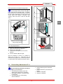
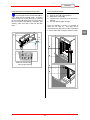
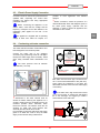
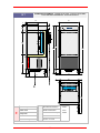
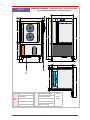
3.4. Description of the Appliance
The Blast chiller-Shock freezer, from now on
defined as appliance, has been designed and built
to cool and/or freeze foodstuffs in the professional
catering ambit.
1) condensation area: it is positioned in the
lower part and is characterised by the
presence of the condensing unit.
2) electric area: it is positioned in the upper
part of the appliance and contains the
control and power supply appliance as
well as electric wiring.
3) evaporation area: it is situated inside the
refrigerated compartment in the rear and
is characterised by the evaporating unit.
4) storage area: it is situated inside the
refrigerated compartment and is destined
for the cooling and/or freezing of
foodstuffs.
The lower part is also distinguished by a control
panel (A) that allows access to the electric parts;
there is a vertically-opening door in the front,
which closes the refrigerated compartment
hermetically.
Depending on requirements, the appliance is
produced in several versions.
10 TRAY BLAST CHILLER-SHOCK FREEZER
Model suitable to contain 10 trays with
blast chilling capacity of 40 kg.
10 TRAY BLAST CHILLER and SHOCK
FREEZER
Model suitable to contain 10 trays with
blast chilling capacity of 40 and 25 in
shock freezing.
10 T "R" BLAST CHILLER and SHOCK
FREEZER
Model suitable to contain 10 “insertion
325” trays with blast chilling capacity of 40
and 25 in shock freezing.
14 TRAY BLAST CHILLER-SHOCK FREEZER
Model suitable to contain 14 trays with
blast chilling capacity of 55 kg.
14 TRAY BLAST CHILLER and SHOCK
FREEZER
Model suitable to contain 14 trays with
blast chilling capacity of 55 and 35 in
shock freezing.
6T 2/1 BLAST CHILLER and SHOCK FREEZER
Model suitable to contain 6
GASTRONORM 2/1trays with blast
chilling capacity of 50 and 30 in shock
freezing.
10 TRAY 2/1 BLAST CHILLER
Model suitable to contain 10
GASTRONORM 2/1 trays with blast
chilling capacity of 75 kg.
10T 2/1 BLAST CHILLER and SHOCK
FREEZER
Model suitable to contain 10
GASTRONORM 2/1trays with blast
chilling capacity of 75 and 50 in shock
freezing.
1
3
-
4
A
2

5
ENGLISH
GB
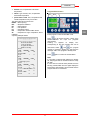
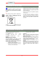
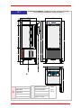
3.5. Features Plate
The identification plate shown is applied directly
onto the appliance. It states the references and all
indications indispensable for working in safety.
1) Appliance code
2) Description of the appliance
3) Serial number
4) Power supply voltage and frequency
5) Electrical absorption
6) Climatic class
7) Type and Amount of refrigerant gas
8) WEEE symbol
4. SAFETY
iIt is recommended to carefully read the
instructions and warnings contained in this
manual before using the appliance. The
information contained in the manual is
fundamental for the safety of use and for machine
maintenance.
! Keep this manual carefully so that it can be
consulted when necessary.
i The electric plant has been designed in
compliance with the IEC EN 60335-2-24
Standard.
, Specific adhesives highlight the presence of
mains voltage in the proximity of areas (however
protected) with risks of an electrical nature.
! Before the connection, ensure the presence of
an omnipolar switch with minimum contacts
opening equal to 3 mm in the mains power supply
upstream from the appliance (requested for
appliances supplied without plug to connect to the
fixed plant).
In the design and construction phase, the
manufacturer has paid particular attention to the
aspects that can cause risks to safety and health
of persons that interact with the appliance.
Carefully read the instructions stated in the
manual supplied and those applied directly to the
machine, and particularly respect those regarding
safety.
Do not tamper or eliminate the installed safety
devices. Failure to comply with this requisite can
lead to serious risks for personal health and
safety.
It is recommended to simulate some test
manoeuvres in order to identify the controls, in
particular those relative to switch-on and switch-
off and their main functions.
The appliance is only destined for the use for
which it has been designed; any other use must
be considered improper.
iThe manufacturer declines all liability for any
damage to objects or injury to persons owing to
improper or incorrect use.
i All maintenance interventions that require
precise technical skill or particular ability must be
performed exclusively by qualified staff.
1
2
3
4
5
6
7
8

6
ENGLISH
GB
! When using the appliance, never obstruct the
air inlet when the appliance is on, so as not to
compromise its performance and safety.
! Never stretch the power cable.
In order to guarantee hygiene and protect the
foodstuffs from contamination, the elements that
come into direct or indirect contact with the
foodstuffs must be cleaned very well along with
the surrounding areas. These operations must
only be performed using detergents that can be
used with foodstuffs, avoiding inflammable
products or those that contain substances that are
harmful to personal health.
In the case of prolonged inactivity, as well as
disconnecting all the supply lines, it is necessary
to accurately clean all internal and external parts
of the appliance.
4.1. Safety Devices
During the running of appliance, some control
devices may activate and govern the correct
running of the machine. In other cases, they may
deactivate parts or the whole machine, to put the
appliance in safe conditions. The main controls
are listed.
Door micro switch
If the door is opened, the
magnetic switch placed on the control board
opens and, during blast-chilling or shock-freezing,
evaporator fans go off and a warning message
appears on the display at the same time. This
condition may also be determined when the door
is not perfectly aligned to or near the control
board: in this case with the machine in the STOP
phase, no cycle may be started.
If a U.V. sterilisation cycle is active, the
functioning of the U.V. lamp is interrupted. The
cycle continues when the door is closed.
Protective Fuses
Some protection fuses in the general power
supply line are activated in case of overload.
Other fuses are prepared for the evaporator fans.
Thermal relay
In the case of faulty operation
that results in exceeding the current absorption
limits of the electric system, the thermal relay will
operate to stop the machine. This intervention is
shown on the display by means of the wording
“HA”. If the circuit breaker relay has intervened, it
must be restored manually (see specific chapter).
High and low pressure switches
If, due to
environmental conditions or faulty operation, the
minimum/maximum pressure values in the
refrigerating circuit should become excessive, the
maximum/minimum safety pressure switch (in the
5 Pans version, only the maximum safety
pressure switch) will operate to stop the
appliance. The machine can be switched on again
only after the pressure has returned to an
acceptable value. If a high pressure alarm should
occur, the wording “HP” will appear on the
display. The wording “LP” will appear if there is a
low pressure alarm.
Evaporator Fan Micro switch
If the deflector is opened to
inspect the evaporator or fans, this micro switch
positioned on the evaporator deflector,
deactivates machine functioning. Closure of the
deflector with the successive disappearance of
the alarm on the display, restores normal machine
functioning.

7
ENGLISH
GB
5. USE AND FUNCTIONING
5.1. Description of the Functioning Cycles
The following are brief descriptions and types of
operating cycles.
Temperature Blast Chilling
This cycle allows a reduction in temperature in the
product core from +90°C to +3°C as quickly as
possible and within a MAX time of 90 minutes.
The cycle ends when the value +3°C, read by the
needle probe, is reached.
Time Blast Chilling
This cycle allows a reduction in temperature in the
product core from +90°C to +3°C during the set
time: we remind you that it is advisable to run
some previous testing temperature cycles so to
determine the necessary time for a correct
product blast chilling process. Do not forget that
acquired times and eventually memorised have to
be considered valid for exclusive use of the same
type of product and in the same quantities per
cycle.
Intensive timed blast chilling
For the use of this cycle, the information
contained in the previous paragraph is applicable
concerning the time which can be set and the final
temperature of the product.
The use of this function, which makes it possible
to reduce chilling times, is recommended for foods
with the following characteristics:
Ø Packaged foods or foods in containers
Ø Foods with a thickness greater than 50
mm
Ø Foods with a high fat content
Temperature Shock Freezing
This cycle allows a reduction in temperature in the
product core from +90°C to -18°C as quickly as
possible and within a MAX time of 270 minutes.
The cycle ends when the value -18°C, read by the
needle probe, is reached.
Time Shock Freezing
This cycle allows a reduction in temperature in the
product core from +90°C to -18°C during the set
time: we remind you that it is advisable to run
some previous automatic test cycles so to
determine the necessary time for a correct
product blast chilling process. Do not forget that
acquired times and eventually memorised have to
be considered valid for exclusive use of the same
type of product and in the same quantities per
cycle.
SOFT Time Shock Freezing
The use of this function is recommended in the
presence of foodstuffs that fear a large initial heat
shock or foodstuffs with different ingredients as
composition (e.g.: fresh pasta) and therefore
require slower and homogeneous shock freezing.
Preservation
At the end of each cycle as described above,
either temperature or time cycle, the preservation
cycle will be started automatically, with no time
limit. The freezer temperature will refer to last
cycle, just concluded:
Ø + 3°C for blast chilling
Ø -25°C for shock-freezing
Warning: use of this cycle is recommended only
for short periods prior to storage of the product in
a storage unit or in case of emergency, so as to
avoid such a limited use of a machine with such
high potential.
Defrosting
The frost forming on the evaporator following the
deposit of humidity from the product can
jeopardise the correct functioning of the
appliance. A defrosting cycle must be carried out
to restore full functionality.
The defrosting cycle ends automatically when the
set temperature is reached.

8
ENGLISH
GB
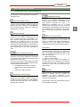
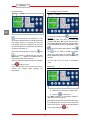
5.2. Description of the Controls
Below is a brief description of the functions carried
out by the keys on the control panel.
Temperature Blast chilling Key
By pressing the key with the machine at a
standstill, it allows to select a temperature blast
chilling cycle (+90°Cà+3°C).
Time Blast chilling Key
By pressing the key with the machine at a
standstill, it allows to select a time blast chilling
cycle.
Time Blast chilling Key
By pressing the key with the machine at a
standstill, it allows to select a temperature shock
freezing cycle (+90°Cà-18°C).
Time Shock freezing Key
By pressing the key with the machine at a
standstill, it allows to select a time shock freezing
cycle.
Intensive Cycle Key
The key is active in the time cycles. If pressed
after a blast chilling cycle has been selected, it
selects the intensive function; if pressed after a
shock freezing cycle has been selected, it selects
the SOFT function.
If pressed for 5 seconds with the machine
stopped, it makes it possible to set the current
time, day and year
.Time increase and decrease keys
When the time blast chilling and/or shock freezing
mode is selected, these buttons allow to set the
cycle duration.
If is pressed during automatic temperature-
regulated cycle, it makes it possible to change
from the display of the needle temperature to the
display of the compartment temperature (display
DY1).
If is pressed during a temperature-regulated
cycle, it makes it possible to pass from the display
of the remaining time to display of the real time
passed from the start of the cycle (display DY2).
Pressing both keys simultaneously makes it
possible to enter parameters programming mode.
Cycle start key
Once a cycle has been selected, press this button
to start the cycle.
If it is pressed during functioning the appliance
stops; the setting of the previous cycle selected
remains, which can be started immediately.
By pressing this button for at least 5 seconds the
machine passes to the stand-by mode. Repeat
the procedure to reactivate the board.
DEFROST key
When the machine is off a manual defrosting
cycle can be started.
The defrosting cycle ends automatically when the
set temperature is reached.
Heated Probe Key
In appliances in which the needle probe can be
heated, once this key is pressed with the machine
stopped, makes it possible to heat the needle
probe so that it is easier to pull it out of the frozen
product.
If during a chilling / freezing cycle the "needle
probe not inserted" alarm is signalled (see
paragraph on alarms), press the key to silence the
alarm after checking that the needle probe is
properly inserted into the product, then restore
automatic operation.
Germicidal lamp key
With the machine stopped and the door closed, it
makes it possible to switch on an internally
located UV lamp for a set time. This lamp
sterilises the compartment at the beginning and at
the end of the day after it has been cleaned.
Programmes Selection Key
With the machine at a standstill, it makes it
possible to recall and/or memorise 99 timed
chilling or freezing programs.
DY1
DY2

9
ENGLISH
GB
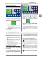
5.3. Functionality
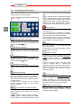
Temperature Blast Chilling (+90 à+3°C)
Select positive chilling by pressing (the
corresponding LED switches on) confirmed by the
lighting of LED L4. The display DY2 shows the
maximum possible time for this cycle: 90 minutes.
Insert the needle probe into the product.
Start the cycle by pressing the key (the
corresponding LED switches on). The start of the
cycle is also confirmed by LED L1 switching on.
During the first minutes of operation, the control
unit checks the exact positioning of the needle
probe.
The appearance on display DY1 of
the “o - -” message accompanied by
an intermittent sound means that the
verification of the correct insertion of
the product probe has given a
negative result and therefore the reading on the
needle probe cannot be considered as valid. The
control unit activates a timed safety cycle (LEDL4
switches off and LED L5switches on).
To silence the alarm and re-activate the automatic
temperature-regulated cycle, re-position the
needle probe and then press (LED L5
switches off and LED L4 switches on).
If the product has not reached 3°C
after 90 minutes the cycle is not
concluded: the buzzer is triggered
intermittently and indicators DY1 and
DY2 indicate the temperature of the
product and “OUt“ respectively.
The blast chilling cycle is concluded
successfully as soon as the
temperature measured by the
product probe reaches 3°C: the
buzzer is triggered intermittently and indicators
DY1 and DY2 indicate “End” and “---“
respectively. An automatic preservation cycle is
activated (LEDL1 switch off and L2 switch on).
Press to conclude the preservation cycle.
Time Blast Chilling
Select positive chilling by pressing (the
corresponding LED switches on) confirmed by the
lighting of LED L5.
If you wish to choose the intensive chilling cycle,
press (the corresponding LED switches on)
Select the required blast chilling time using keys
and .
Start the cycle by pressing the key (the
corresponding LED switches on). The start of the
cycle is also confirmed by LED L1 switching on.
The correct conclusion of the cycle is
signalled by the “End” message on
display DY2 and by an intermittent
noise for a few seconds.
At the end of the set time, the blast chilling cycle
is concluded and a preservation cycle is
automatically started (LED L1 switch off and
LEDL2 switch on).
Press to conclude the preservation cycle.
Notes: the duration of the intensive phase is
calculated automatically by the control unit based
on the set time; the final part of the cycle does
however take place in normal mode to avoid
surface freezing of the product and is confirmed
by the extinguishing of the LED that corresponds
to .
1
L5
L1
L2
1
L4
L
1
L2

10
ENGLISH
GB
Temperature Shock Freezing (+90 à-18°C)
Select freezing by pressing (the
corresponding LED switches on) confirmed by the
lighting of LED L4. The display DY2 shows the
maximum possible time for this cycle: 270
minutes.
Insert the needle probe into the product.
Start the cycle by pressing the key (the
corresponding LED switches on). The start of the
cycle is also confirmed by LED L1 switching on.
During the first minutes of operation, the control
unit checks the exact positioning of the needle
probe.
The appearance on display DY1 of
the “o - -” message accompanied by
an intermittent sound means that the
verification of the correct insertion of
the product probe has given a
negative result and therefore the reading on the
needle probe cannot be considered as valid. The
control unit activates a timed safety cycle (LEDL4
switches off and LED L5switches on).
To silence the alarm and re-activate the automatic
temperature-regulated cycle, re-position the
needle probe and then press (LED L5
switches off and LED L4 switches on).
If the product has not reached -18°C
after 270 minutes the cycle is not
concluded: the buzzer is triggered
intermittently and indicators DY1 and
DY2 indicate the temperature of the
product and “OUt“ respectively.
The shock freezing cycle is
concluded successfully as soon as
the temperature measured by the
product probe reaches -18°C: the
buzzer is triggered intermittently and indicators
DY1 and DY2 indicate “End” and “---“
respectively. An automatic preservation cycle is
activated (LEDL1 switch off and L2 switch on).
Press to conclude the preservation cycle.
Time Shock Freezing (+90 à-18°C)
Select freezing by pressing (the
corresponding LED switches on) confirmed by the
lighting of LEDL5: in this cycle the intensive
function is activated automatically (the
corresponding LED switches on )
If you wish to choose the SOFT freezing cycle,
press (the corresponding LED switches off)
Select the required shock freezing time using keys
and .
Start the cycle by pressing the key (the
corresponding LED switches on). The start of the
cycle is also confirmed by LED L1 switching on.
The correct conclusion of the cycle is
signalled by the “End” message on
display DY2 and by an intermittent
noise for a few seconds.
At the end of the set time, the shock freezing
cycle is concluded and a preservation cycle is
automatically started (LED L1 switch off and LED
L2 switch on).
Press to conclude the preservation cycle.
HACCP data printer (Optional)
If the printer is enabled, the following events are
printed:
Ø print heading : date, time and selected cycle;
Ø cycle start: compartment and needle
temperature;
Ø alarms : type of alarm, time, compartment
and needle temperature;
Ø cycle end: time, compartment and needle
temperature;
Ø start preservation: time, compartment and
needle temperature;
1
L5
L1
L2
1
L4
L1
L2

11
ENGLISH
GB
Ø Defrost: time, compartment and needle
temperature;
Ø alarms : type of alarm, time, compartment
and needle temperature;
Ø preservation record: time, compartment and
needle temperature every 30 minutes:
The alarms that can be printed are:
DOOR →Door opening
DFL →Evaporator deflector
HP →High pressure
LP →Low pressure
HT →Condenser high T
HA →Compressor circuit breaker switch
AL →Compartment high temperature alarm
(HACCP)
A printing example follows.
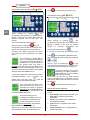
Programs Memorisation
To memorise a work cycle, set it as if it were a
timed program in machine standstill mode.
Press for at least 5 seconds, a beep of the
buzzer confirms the input into programs
memorisation.
Flashing P1 appears on display DY1
corresponding to the first program that can be
memorised; select and the program
number to memorise: display DY2 will show the
message "USE" if the program is already used.
Press again to confirm the memorisation.
Note:
If a program is selected with data that is already
set, this program will be overwritten with the newly
set data.
If more than ten seconds have passed since the
last key pressed, DY1 will once again display the
temperature. Memorisation will be exited and the
program will not be memorised.
************************
------------
************************
Date:24/09/2004
Time:12:28:45
Program:Automatic
CORE Freezing
Start
TIME CHAMBER CORE
0:00 20 62
Alarm:DOOR
0:55 1 11
End
TIME CHAMBER CORE
1:35 -3 3
Holding Cycle
Start
TIME CHAMBER CORE
18:10 -3 4
18:40 3 3
********DEFROSTING*****
18:45 6 3
Alarm: DOOR
18:55 8 3
1
DY1
DY2

12
ENGLISH
GB
Programs Recall
With the machine stopped, press and release
(the corresponding LED switches on). The
temperature display shows the code P followed by
the program number, for example P1, while the
time display shows the memorised set time and
the LED indicators that correspond to the selected
operating mode switch on.
Select the required program using keys and
. If a program is selected that has not been
memorised, “ --- “ appears on the display and the
blast chilling mode LEDs remain off.
Once the required programme has been selected,
press to start the cycle.
If ten seconds pass from the last time a key is
pressed the display DY1 displays the
temperature.
4.4.3. Setting the time and date
To access time setting, press for at least five
seconds.
The display DY1 will show Hr (hours), Mn
(minutes), dA (day), Mo (month) and Yr (year),
while display DY2 will display the settings relative
to the abbreviations shown by display DY1. Press
to scroll the various abbreviations, while
and can be used to update the relative
values. Exit timer setting by pressing after
having displayed Yr (year) or due to timeout of 10
seconds.
The new data set for the timer is immediately
active
Defrosting
v Make sure the machine is in STOP mode.
v Press key for defrosting.
The “DEF” message on the display indicates a
defrosting cycle is in progress.
Defrosting is performed by forced ventilation using
the evaporating fans; the cycle may be performed
with the door open or closed and be interrupted at
any time by pressing the key.
DY1
DY2
1
1
1
DY1
DY2

13
ENGLISH
GB
Needle Probe Heating (Optional)
At the end of a work cycle, press (the
corresponding LED switches on) to activate
needle probe heating, which will make it easier to
extract the probe from the frozen product. Display
DY1 will show ‘Prb’:
This function is not active if:
· the needle probe provided is not a type
which can be heated
· the temperature of the needle probe is
greater than 0°C
The cycle is automatically interrupted at the end of
the envisioned time.
UV lamp (optional)
At the end of the job, after having cleaned the
compartment, press (the relative LED
switches on) compartment sterilization is
activated using the ultra-violet light; display DY1
shows ‘StE’:
This cycle can be started only with the door
closed and it will be interrupted immediately if the
door is opened during sterilization.
For correct machine efficiency and hygiene, it is in
any case advisable to clean the compartment
thoroughly each time you finish using the
machine.
5.4. Recommendations for Use
Prolonged Inactivity
If the appliance remains inactive for a long period,
proceed as follows:
1. Use the automatic isolating switch to
deactivate connection to the main electrical
line.
2. Clean the appliance and surrounding areas
thoroughly;
3. Spread a thin layer of cooking oil onto the
stainless steel surfaces;
4. Carry out all maintenance operations;
5. Leave the doors ajar to prevent the formation
of mould and/or unpleasant odours.
Recommendations for normal use
In order to ensure correct use of the appliance, it
is good practice to apply the following
recommendations:
! Do not obstruct the zone in front of the
condensing unit in order to favour heat disposal
from the condenser to a maximum.
Always keep the front of the condenser clean.
áDo not insert foodstuffs that are well above
the temperature of 65°C. As well as initially
overloading the machine it can make protections
intervene that prolong temperature descent times.
If possible, a brief external period is useful to
lower the temperature to acceptable values.
Check the planarity of the appliance rest surface.
i Do not stack the materials to be preserved
in contact with the internal walls, so blocking the
circulation of air, which guarantees uniformity of
the internal temperature of the refrigerated
compartment.
i There must be a sufficient space between
the basins and trays used in order to guarantee a
sufficient flow of cold air on the entire product.
Therefore avoid the following positions of trays
and/or basins stated below.
i Never obstruct the inlet of the evaporator
fans.
1
1
DY1

14
ENGLISH
GB
i Products that are more difficult to chill
because of their composition and size should be
placed in the centre.
Limit the number of times and the duration of time
the doors are opened.
! Blast chilling data refer to standard products
(low fat content) with a thickness below 50 mm;
therefore avoid overlaying products or the
insertion of pieces with a much higher thickness.
This would, in fact, lead to an extension of blast
chilling times. Always distribute the product well
on the trays or basins or in the case of thick
pieces decrease the amount to blast chill.
iAfter blast chilling/shock freezing the
product, it can be stored in a preservation cabinet
after having been duly protected. A tag should be
applied describing the contents of the product,
blast chilling/shock freezing date and expiry date.
When the product has been blast chilled it must
be preserved at a constant temperature of +2°C ,
while if it has been shock frozen it must be
preserved at a constant temperature of -20°C.
i The chiller should be used for storage for
short periods only.
! To prevent bacterial contamination or
contamination of any other biological nature,
the needle probe must be disinfected after
use.
! To extract the product that has undergone blast
chilling or shock freezing, always wear gloves to
protect the hands, as "burns" may occur from the
cold.
i Blast chilling Cycle
With this operating modality the chiller keeps the
temperature of the refrigerating compartment
close to zero during the entire chilling process in
order to ensure a gradual drop in the temperature
of the product to +3°C. In this way, ice crystals do
not form on the surface of the product. This cycle
should be used preferably for products that are
not packed and whose physical/organoleptic
characteristics could be damaged by the
formation of superficial ice (e.g. fish).
i Intensive Blast Chilling Cycle
With this operating mode, at the beginning the
chiller maintains the temperature of the
refrigerating compartment at a much lower than
the value set for normal chilling, in order to
accelerate the drop in temperature of the product.
When the product reaches the fixed temperature
(temperature at which ice could form on the
external surface product) the internal temperature
of the compartment rises to the temperature set
for normal positive chilling. This blast chilling
method should be used preferably for products
that are packed and whose physical/organoleptic
characteristics are not damaged by the formation
of superficial ice.
i Shock freezing Cycle
With this chilling modality the chiller maintains the
temperature value in the compartment below -
18°C, which is the end temperature of shock
freezing. For shock freezing to be successful and
fast, food should be in small pieces, especially if it
has a high fat content. The largest pieces should
be placed in central trays. If it takes longer than
standard time to shock freeze and the sizes
cannot be reduced, decrease the quantity and
precool the chiller compartment by starting an
empty shock freezing cycle before shock freezing
the product.
i Shock freezing Cycle SOFT
In this case, the shock freezing cycle is divided in
two phases that differ depending on the
compartment set point used. The first phase
consists in a cycle around the compartment set
point defined for normal blast chilling. The
passage to the second phase starts when the
core-probe reaches a pre-defined temperature
exchange value or when the time elapsed is equal
to a pre-set percentage of the total time. In the
second phase, the compartment reference set
point will be the same as the shock freezing one.
This type of shock freezing allows a more even
freezing of the product, avoiding the external
formation of ice when the core temperature is still
high.

15
ENGLISH
GB
6. CLEANING AND MAINTENANCE
6.1. Recommendations for Cleaning and Maintenance
! Activate all envisioned safety devices before
carrying out any maintenance interventions. In
particular, deactivate the electrical power supply
using the automatic isolating switch.
6.2. Routine Maintenance
Routine maintenance consists of daily cleaning of
all the parts which can come into contact with
foodstuffs and the periodic maintenance of the
burners, nozzles and draining pipes.
Correct maintenance allows the user to maximise
performance levels and operating life and
constantly maintain safety requirements.
Do not spray the appliance with direct jets of
water or using high pressure appliances.
Do not use iron wool, brushes or scrapers to clean
the stainless steel as ferrous particles could be
deposited which, on oxidising, could lead to rust.
To remove hardened residues, use wooden or
plastic spatulas or abrasive rubber pads.
During long periods of inactivity, spread a
protective layer on all stainless steel surfaces by
wiping them with a cloth soaked in Vaseline oil
and airing the rooms periodically.
! Do not use products which contain substances
which are harmful and dangerous for personal
health (solvents, petrol etc.).
At the end of the day it is advisable to clean:
Ø the cooling compartment
Ø the appliance.
6.3. Extraordinary Maintenance 10T and 14T
iHave the following operations carried out
periodically by specialised staff:
Ø Check the perfect sealing of the door
gaskets and replace them if necessary.
Ø Check that the electric connections have
not loosened.
Ø Check the efficiency of the heating
element resistance
Ø Check functioning of the board and
probes.
Ø Check the efficiency of the electrical
system.
Ø Clean the evaporator.
Ø Clean the condenser.

16
ENGLISH
GB
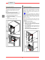
Cleaning the evaporator
Clean the evaporator periodically.
! As the fins of the evaporator are very sharp,
always wear protective gloves for the next
phases.
i Only a brush must be used for cleaning: do
not use jets of liquid or sharp instruments.
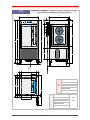
To access the evaporator proceed as follows:
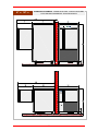
1. Open the door (A) of the appliance.
2. Remove the runners (B):
3. Loosen the two screws (C) on the right of the
deflector.
4. Turn the deflector (D) to the left
Cleaning the condenser
Clean the condenser periodically.
! As the fins of the condenser are very sharp,
always wear protective gloves for the next
phases. Use protective masks and glasses in the
presence of dust.
i Whenever the condenser has a deposit of
dust in correspondence with the fins, this can be
removed using a suction device or with a brush
applied, using a vertical movement along the
direction of the fins.
! No other instruments must be used, which may
deform the fins and therefore the efficiency of the
appliance.
To clean, proceed as follows:
1. Open the door (A) of the appliance.
2. Remove the lower panel (B) from the
technical compartment: to do this, remove
the screw fasteners (C).
3. It is now possible to clean the finned part
of the condenser (D) using suitable tools
and protection devices.
4. After cleaning, close the control panel and
fix it with the screws removed beforehand.
C
B
D
C
C
A
B
D
A
C
B

17
ENGLISH
GB
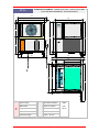
Fuse replacement and thermal relay rearm
i The fuses (A) and the thermal relay (B) are
in the upper part of the blast chiller. To access
these just open the control panel (C) by loosening
the two screws positioned in the lower part of the
control panel and rotating it upwards. After
opening, make sure that it does not fall back
down.
U.V. Lamp Replacement
To access the evaporator proceed as follows:
1. Open the door (A) of the appliance.
2. Remove the runners (B):
3. Loosen the two screws (C) on the front of the
deflector.
4. Turn the deflector (D) to the right.
Once the deflector is turned, it is possible to
switch the UV lamp on. That lamp can be
removed turning it (E). Carry out all the operations
in reverse order after having removed the U lamp.
6.4. Extraordinary Maintenance 10TR
iHave the following operations carried out
periodically by specialised staff:
Ø Check the perfect sealing of the door
gaskets and replace them if necessary.
Ø Check that the electric connections have
not loosened.
Ø Check the efficiency of the heating
element resistance
Ø Check functioning of the board and
probes.
Ø Check the efficiency of the electrical
system.
Ø Clean the evaporator.
Ø Clean the condenser.
B
D
C
B
A
E
B
C
A
Rearm the thermal relay
using the grey button

18
ENGLISH
GB
Cleaning the evaporator
Clean the evaporator periodically.
! As the fins of the evaporator are very sharp,
always wear protective gloves for the next
phases.
i Only a brush must be used for cleaning: do
not use jets of liquid or sharp instruments.
To access the evaporator proceed as follows:
1. Open the door (A) of the appliance.
2. Remove the runners (B):
3. Loosen the two screws (C) on the front of the
deflector.
4. Turn the deflector (D) to the left
Cleaning the condenser
Clean the condenser periodically.
! As the fins of the condenser are very sharp,
always wear protective gloves for the next
phases. Use protective masks and glasses in the
presence of dust.
iWhenever the condenser has a deposit of
dust in correspondence with the fins, this can be
removed using a suction device or with a brush
applied, using a vertical movement along the
direction of the fins.
! No other instruments must be used, which may
deform the fins and therefore the efficiency of the
appliance.
To clean, proceed as follows:
1. Open the door (A) of the appliance.
2. Remove the lower panel (B) from the
technical compartment: to do this, remove the
screw fasteners (C).
3. It is now possible to clean the finned part of
the condenser (D) using suitable tools and
protection devices.
4. After cleaning, close the control panel and fix
it with the screws removed beforehand.
C
B
D
C
C
A
B
D
D
A
C
B
La pagina si sta caricando...
La pagina si sta caricando...
La pagina si sta caricando...
La pagina si sta caricando...
La pagina si sta caricando...
La pagina si sta caricando...
La pagina si sta caricando...
La pagina si sta caricando...
La pagina si sta caricando...
La pagina si sta caricando...
La pagina si sta caricando...
La pagina si sta caricando...
La pagina si sta caricando...
La pagina si sta caricando...
La pagina si sta caricando...
La pagina si sta caricando...
La pagina si sta caricando...
La pagina si sta caricando...
La pagina si sta caricando...
La pagina si sta caricando...
La pagina si sta caricando...
La pagina si sta caricando...
La pagina si sta caricando...
La pagina si sta caricando...
La pagina si sta caricando...
La pagina si sta caricando...
La pagina si sta caricando...
La pagina si sta caricando...
La pagina si sta caricando...
La pagina si sta caricando...
La pagina si sta caricando...
La pagina si sta caricando...
La pagina si sta caricando...
La pagina si sta caricando...
-
 1
1
-
 2
2
-
 3
3
-
 4
4
-
 5
5
-
 6
6
-
 7
7
-
 8
8
-
 9
9
-
 10
10
-
 11
11
-
 12
12
-
 13
13
-
 14
14
-
 15
15
-
 16
16
-
 17
17
-
 18
18
-
 19
19
-
 20
20
-
 21
21
-
 22
22
-
 23
23
-
 24
24
-
 25
25
-
 26
26
-
 27
27
-
 28
28
-
 29
29
-
 30
30
-
 31
31
-
 32
32
-
 33
33
-
 34
34
-
 35
35
-
 36
36
-
 37
37
-
 38
38
-
 39
39
-
 40
40
-
 41
41
-
 42
42
-
 43
43
-
 44
44
-
 45
45
-
 46
46
-
 47
47
-
 48
48
-
 49
49
-
 50
50
-
 51
51
-
 52
52
-
 53
53
-
 54
54


Whirlpool ADN 255 Guida utente
- Tipo
- Guida utente
in altre lingue
- English: Whirlpool ADN 255 User guide
Documenti correlati
Altri documenti
-
Sirman WSIR0230 Manuale utente
-
Hendi 943564 Manuale utente
-
Metos TN Istruzioni per l'uso
-
Phcbi MPR-514R Istruzioni per l'uso
-
Hendi 232064 Manuale utente
-
Candy 31100548 Scheda dati
-
-
-
Pfannenberg EB 260 Series Quick Instruction
-
Bartscher 104204 Istruzioni per l'uso