Genius Encoder Kit 24V Istruzioni per l'uso
- Tipo
- Istruzioni per l'uso

1
ENCODER 24V
Fig. 1
Fig. 2
Fig. 3
Fig. 4
ITALIANO
L’encoder può essere utilizzato solo con apparecchiature elettroniche
che ne prevedono l’utilizzo
Il funzionamento dell’encoder è descritto nelle istruzioni dell’apparec-
chiatura elettronica.
Questo encoder può essere montato solo su operatori a 24V della
gamma Falcon o Milord
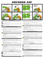
ISTRUZIONI DI MONTAGGIO SUL FALCON 424
Per installare correttamente l’encoder agire come di seguito:
Posizionare la scheda elettronica (Fig. 1 rif. b) sul corpo motore, inse-
rendo tra la scheda ed il corpo motore le quattro rondelle in dotazione
(Fig. 1 rif. a).
Fissare la scheda con le quattro viti M4x10 in dotazione.
Posizionare il disco di lettura (Fig. 2 rif. a) all’interno del foro e fissarlo
utilizzandola vite M4x30 fornita.
Prima di posizionare il disco di lettura si consiglia di mettere una goccia
di frenafiletti tipo medio (es. Loctite 222 o similare) all’interno del foro
filettato dell’albero motore. Questo evita che, a causa delle continue
inversioni di rotazione, il disco si allenti e quindi l’encoder non funzioni
correttamente.
Collegare alla scheda i tre fili forniti rispettando lo schema di collega-
mento di fig. 3.
Posizionare il coperchio di protezione (Fig. 4 rif. a).
Per il collegamento dell’encoder nella centrale di comando seguire le
istruzioni riportate nel manuale della scheda elettronica.
ISTRUZIONI DI MONTAGGIO SUL MILORD 424
Per installare correttamente l’encoder agire come di seguito:
Posizionare la scheda elettronica (Fig. 5 rif. b) sulla calotta motore,
inserendo tra la scheda e la calotta le quattro rondelle in dotazione
(Fig. 5 rif. a).
Fissare la scheda con le quattro viti M4x10 in dotazione.
Posizionare il disco di lettura (Fig. 6 rif. a) all’interno del foro e fissarlo
utilizzandola vite M4x30 fornita.
Prima di posizionare il disco di lettura si consiglia di mettere una goccia
di frenafiletti tipo medio (es. Loctite 222 o similare) all’interno del foro
filettato dell’albero motore. Questo evita che, a causa delle continue
inversioni di rotazione, il disco si allenti e quindi l’encoder non funzioni
correttamente.
Collegare alla scheda i tre fili forniti rispettando lo schema di collega-
mento di fig. 7.
Posizionare il coperchio di protezione (Fig. 8 rif. a).
Per il collegamento dell’encoder nella centrale di comando seguire le
istruzioni riportate nel manuale della scheda elettronica.
ENGLISH
The encoder can only be used with control boards allowing its use
The operation of the encoder is described in the instructions of the
control board.
This encoder can only be fitted on 24V-operators of the Falcon or Milord
range
ASSEMBLY INSTRUCTIONS FOR FALCON 424
1.
2.
3.
4.
5.
6.
1.
2.
3.
4.
5.
6.
For a correct installation of the encoder, follow the instructions below:
Place the control board (Fig. 1 ref. b) on the motor body, inserting the
four supplied washers between the board and the motor body (Fig. 1
ref. a).
Secure the board with the four supplied screws M4x10.
Place the reading disc (Fig. 2 ref. a) in the hole and secure it with the
supplied screw M4x30.
Before positioning the reading disc we recommend you to apply a
drop of medium-type threadlocker (i.e.. Loctite 222 or equivalent) in
the threaded hole of the motor shaft. This prevents the disc from loo-
sening due to the continuous rotation reversals causing an incorrect
operation of the encoder.
Connect the three supplied wires to the board observing the wiring
diagram in fig. 3.
Place the protection cover (Fig. 4 ref. a).
For the connection of the encoder in the control unit, refer to the in-
structions in the control board manual.
ASSEMBLY INSTRUCTION FOR MILORD 424
For a correct installation of the encoder, follow the instructions below:
Place the control board (Fig. 5 ref. b) on the motor cover, inserting
the four supplied washers between the board and the cover (Fig. 5
ref. a).
Secure the board with the four supplied screws M4x10.
Place the reading disc (Fig. 6 ref. a) in the hole and secure it with the
supplied screw M4x30.
Before positioning the reading disc we recommend you to apply a
drop of medium-type threadlocker (i.e. Loctite 222 or equivalent) in the
threaded hole of the motor shaft. This prevents the disc from loosening
due to the continuous rotation reversals causing an incorrect operation
of the encoder.
Connect the three supplied wires to the board observing the wiring
diagram in fig. 7.
Place the protection cover (Fig. 8 ref. a).
For the connection of the encoder in the control unit, refer to the in-
structions in the control board manual.
FRANÇAIS
L’encodeur ne peut être utilisé qu’avec des armoires électroniques
qui en prévoient l’utilisation
Le fonctionnement de l’encodeur est décrit dans les instructions de
l’armoire électronique.
Cet encodeur ne peut être monté que sur des opérateurs à 24V de
la gamme Falcon ou Milord
INSTRUCTIONS DE MONTAGE SUR FALCON 424
Pour installer correctement l’encodeur, agir comme suit:
Positionner la carte électronique (Fig. 1 réf. b) sur le corps du moteur,
en introduisant entre la carte et le corps du moteur les quatre rondelles
fournies (Fig. 1 réf. a).
Fixer la carte avec les quatre vis M4x10 fournies.
Positionner le disque de lecture (Fig. 2 réf. a) à l’intérieur du trou et le
fixer au moyen de la vis M4x30 fournie.
Avant de positionner le disque de lecture, on recommande de mettre
une goutte de frein-filet de type moyen (ex. Loctite 222 ou similaire) à
l’intérieur du trou taraudé de l’arbre moteur. Cela évite, vu les inver-
1.
2.
3.
4.
5.
6.
1.
2.
3.
4.
5.
6.
1.
2.
3.
Fig. 5
Fig. 8
Fig. 7
Fig. 6
La pagina si sta caricando...
-
 1
1
-
 2
2


Genius Encoder Kit 24V Istruzioni per l'uso
- Tipo
- Istruzioni per l'uso
in altre lingue
- English: Genius Encoder Kit 24V Operating instructions
- français: Genius Encoder Kit 24V Mode d'emploi
- español: Genius Encoder Kit 24V Instrucciones de operación
- Deutsch: Genius Encoder Kit 24V Bedienungsanleitung
- Nederlands: Genius Encoder Kit 24V Handleiding
