Axel Falcon VS Manuale utente
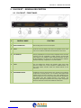
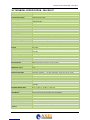
- Categoria
- Schede audio
- Tipo
- Manuale utente


ENG
1 Table of Content
1. INTRODUCTION ......................................................................................................................................................... 5
1.1 FALCON AUDIO PROCESSOR – VERSIONE AVAILABLE .................................................................................................. 5
1.2 OPTION AVAILABLE FOR FALCON AUDIO PROCESSOR SERIE ........................................................................................ 5
1.3 USE OF THIS MANUAL ............................................................................................................................................. 5
1.4 FALCON XT – DEPLIANT AND BROCHURE ................................................................................................................... 6
1.5 COMPARISON TABLE - FALCON AUDIO PROCESSOR .................................................................................................... 8
1 SAFETY WARNINGS / ISTRUZIONI PER LA SICUREZZA ...................................................................................... 9
1.1 FOREWORD ..................................................................................................................................................... 9
2 SAFETY WARNINGS ............................................................................................................................................... 10
3 CONSIGNES DE SÉCURITÉ IMPORTANTES ......................................................................................................... 11
4 ISTRUZIONI IMPORTANTI PER LA SICUREZZA ................................................................................................... 12
5 WICHTIGE SICHERHEITSHINWEISE ...................................................................................................................... 13
6 INSTRUCCIONES IMPORTANTES DE SEGURIDAD ............................................................................................. 15
7 UNPACKING AND INSPECTION ............................................................................................................................. 17
8 FIRST INSTALLATION RECOMMENDATIONS ...................................................................................................... 18
8.1 POWER SUPPLY CABLE ................................................................................................................................ 18
8.2 AC MAINS VOLTAGE SETTING (230 V / 115 V) .............................................................................................. 18
8.3 FUSE REPLACEMENT ................................................................................................................................... 18
8.4 PROTECTION AGAINST LIGHTNING............................................................................................................. 20
8.5 VENTILATION ................................................................................................................................................. 21
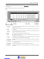
9 FALCON XT – GENERAL DESCRIPTION ............................................................................................................... 22
9.1 FALCON XT – FRONT PANEL .................................................................................................................................. 22
9.2 FALCON XT – REAR PANEL .................................................................................................................................... 23
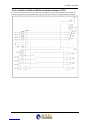
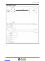
10 BLOCK DIAGRAM OF FALCON XT ................................................................................................................... 25
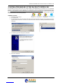
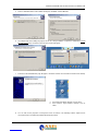
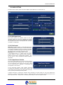
11 INSTALLATION AND USE OF THE FALCON XT CONTROL SW ..................................................................... 26
12 USE OF THE UNIVERSAL TARGET ADDRES MANAGER ............................................................................... 28
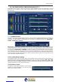
13 USE OF UNIVERSAL REMOTER SOFTWARE .................................................................................................. 29
13.1 “SINGLE TARGET MODE” OR “NETWORK MODE”? ..................................................................................................... 29
13.2 “SINGLE TARGET MODE” CONNECTION ................................................................................................................... 30
13.3 DIRECT UPLINK TO VIA MODEM .............................................................................................................................. 31
13.4 CONNECTION TO A DIAL-UP MODEM ....................................................................................................................... 32
13.5 DIRECT LINK CONNECTION .................................................................................................................................... 33
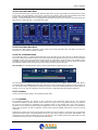
14 FALCON XT CONTROL VIA SOFTWARE ......................................................................................................... 34
14.1 TYPE OF FALCON AUDIO PROCESSOR CONNECTED .................................................................................................. 35
14.2 “SETTINGS” SECTION ........................................................................................................................................... 36
14.2.1 Target Settings: ............................................................................................................................................................. 36
14.2.2 The Falcon XT internal clock: ....................................................................................................................................... 36
14.2.3 Aux Settings - SCA inputs .............................................................................................................................................. 37
14.2.4 Split Circuit: .................................................................................................................................................................. 37
14.2.5 Audio Preset Manager and Alarm:................................................................................................................................ 38
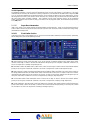
15 THE MPX GENERATOR ..................................................................................................................................... 38
15.1 MPX SECTION ..................................................................................................................................................... 39
15.1.1 MPX Output Level ......................................................................................................................................................... 39
15.1.2 Pilot Control .................................................................................................................................................................. 39
15.1.3 Output Source Selection ................................................................................................................................................ 39
15.1.4 MPX Clipper ................................................................................................................................................................. 40
15.1.5 MPX Output Mode......................................................................................................................................................... 40
15.2 MPX POWER LIMITER CONTROL (ITU-R BS.412) ....................................................................................................... 41
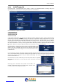
16 AUDIO CONTROL ............................................................................................................................................... 42
16.1 AUDIO INPUTS ..................................................................................................................................................... 43
16.1.1 Analog Input .................................................................................................................................................................. 43
16.1.2 Phase rotator input ........................................................................................................................................................ 44
16.1.3 Digital Input .................................................................................................................................................................. 45
16.1.4 Input Setup and Audio Fault Handler ........................................................................................................................... 45
16.1.5 What are pre-emphasis and de-emphasis and what are they for? ................................................................................. 46
16.2 AUDIO OUTPUTS .................................................................................................................................................. 47
16.2.1 Analog Output ............................................................................................................................................................... 47
16.2.2 Digital Output ............................................................................................................................................................... 47
16.3 SIGNAL GENERATOR ............................................................................................................................................ 48
16.4 AUDIO PRE-PROCESS – THE AGC CONTROL ............................................................................................................ 49
16.4.1 AGC: Automatic Gain Control. ..................................................................................................................................... 49
16.4.2 Drive .............................................................................................................................................................................. 49
16.4.3 Attack and Release ........................................................................................................................................................ 49
16.4.4 Gate Threshold .............................................................................................................................................................. 49
16.4.5 L/R Linkage ................................................................................................................................................................... 50
| INTRODUCTION 2

ENG
16.4.6 Idle Compression and Idle Speed .................................................................................................................................. 50
16.4.7 Work Zone Threshold& Work Zone Release ................................................................................................................. 50
16.4.8 Band Coupling ............................................................................................................................................................... 50
16.4.9 Pre-Process Equalizer ................................................................................................................................................... 50
16.4.10 Speech Detector ........................................................................................................................................................ 50
16.4.11 Stereo Enhancer ....................................................................................................................................................... 51
16.5 AUDIO PROCESS ................................................................................................................................................. 52
16.6 QUALITY OF THE AUDIO MATERIAL IN FALCON XT INPUT ............................................................................................ 53
16.7 MULTIBAND CONTROL AND MULTIBAND PROCESS /1 ................................................................................................. 54
16.8 FALCON XT CROSS OVER FREQUENCY ................................................................................................................... 54
16.9 MULTIBAND CONTROL AND MULTIBAND PROCESS /2 ................................................................................................. 55
16.9.1 Multiband Process: ....................................................................................................................................................... 55
16.9.2 Coupling (Band Coupling) ............................................................................................................................................ 55
16.9.3 Brilliance Control.......................................................................................................................................................... 55
16.9.4 Final Limiter Main Drive .............................................................................................................................................. 56
16.9.5 Final Limiter Bass Drive ............................................................................................................................................... 56
16.9.6 The Lookahead Limiter.................................................................................................................................................. 56
16.9.7 Overdrive ....................................................................................................................................................................... 56
16.9.8 SuperBass ...................................................................................................................................................................... 56
16.9.9 Expander ....................................................................................................................................................................... 57
16.9.10 Super Bass Harmonizer ............................................................................................................................................ 57
16.9.11 Final Limiter Section ................................................................................................................................................ 57
16.10 PRESET MANAGER ............................................................................................................................................... 58
16.11 PRESET AUTOMATION SCHEDULER ........................................................................................................................ 59
17 RDS / RBDS GENERATOR - GENERAL SETUP ............................................................................................... 60
17.1 RDS GENERATOR – RDS ENCODER BLOCK DIAGRAM ................................................................................................ 61
17.1.1 ON/OFF, RDS PHASE AND LEVEL............................................................................................................................. 61
17.1.2 UECP OR NON-UECP COMPATIBLE PROGRAMMING MODES ............................................................................ 61
17.2.1 CHARACTER TABLES (FOR RT, PS, PTYN SERVICES) ............................................................................................ 62
17.2.2 ACTIVE DATASET AND ALTERNATIVES DATASET ................................................................................................. 62
17.2.3 TA CONTROL (TYPE 15B GROUPS) EON - TA Control ............................................................................................. 62
17.3 FALCON XT ACCESS RIGHTS.................................................................................................................................. 63
17.4 STATIC RDS SETTING IN FALCON XT ....................................................................................................................... 64
17.5 INTERNAL CLOCK SYNCHRONIZATION AND “CT” SERVICE ENABLING ............................................................................ 64
18 DATASET 1 CONFIGURATION .......................................................................................................................... 65
18.1 INTRODUCTION TO DATASET1 .................................................................................................................... 65
18.2 RDS GROUP CONFIGURATION (‘SERVICE’ PANEL).................................................................................... 65
18.3 EON/PSN SERVICES IN DATASET 1 ............................................................................................................. 66
18.4 PI (PROGRAMME IDENTIFIER) CODE........................................................................................................... 67
18.4.1 PROGRAM IDENTIFIER CODE IN RDS MODE ........................................................................................................ 67
18.4.2 PROGRAM IDENTIFIER CODE IN RBDS MODE ...................................................................................................... 67
18.5 DI (DECODER IDENTIFIER) ........................................................................................................................... 68
18.6 LINKAGE INFORMATION (LA, EG, ILS, LSN) ................................................................................................. 68
18.7 TP, TA, MS SETTINGS AND RELATIVE REMOTE MANAGEMENT ............................................................... 68
18.8 SLOW LABELLING CODES ............................................................................................................................ 69
18.9 ALTERNATIVE FREQUENCIES (AF) .............................................................................................................. 70
18.10 AF LIST CONSTRUCTION METHOD .............................................................................................................. 71
18.11 “METHOD A” AND “METHOD B” FOR THE ALTERNATIVE FREQ. ................................................................ 73
18.12 RADIO TEXT PANEL ....................................................................................................................................... 75
18.13 PIN – PTY SERVICES ..................................................................................................................................... 76
18.14 PROGRAMME SERVICE NAME ..................................................................................................................... 78
18.15 VARIABLE PS ITEMS - STANDARD OPERATION .......................................................................................... 79
18.15.1 PS SEQUENCES ...................................................................................................................................................... 79
18.16 THE SCHEDULER ........................................................................................................................................... 80
18.16.1 START....................................................................................................................................................................... 82
18.16.2 SELECTING AN ITEM TYPE ................................................................................................................................... 82
18.16.3 SELECTING AN ITEM NUMBER ............................................................................................................................ 82
18.16.4 SETTING THE SCHEDULER TIME AND DATE .................................................................................................... 83
18.16.5 ENABLING AN EVENT ............................................................................................................................................ 85
18.16.6 EVENT REFRESH .................................................................................................................................................... 85
18.16.7 CLEARING A SCHEDULED EVENT ...................................................................................................................... 85
18.16.8 EVENT PRIORITY .................................................................................................................................................... 85
18.16.9 OVERALL SCHEDULER EXAMPLES ..................................................................................................................... 86
18.17 EON NETWORK CONFIGURATION IN DATASET 1 ....................................................................................... 88
19 ALTERNATIVE DATASET 2 - CONFIGURATION AND RECALL ...................................................................... 89
19.1 DATASET 'RECALL' MODE ............................................................................................................................. 89
19.2 SELECTING THE ALTERNATIVE DATASET .................................................................................................. 89
| INTRODUCTION 3

ENG
19.3 DIRECT SELECTION OF DATASET 1 VIA A DIFFERENT DS ........................................................................ 89
20 TECHNICAL APPENDIX ..................................................................................................................................... 90
20.1 APPENDIX A - BALANCED AUDIO CONNECTION AND PINOUT .................................................................. 90
20.2 APPENDIX B - SERIAL CONNECTION E PINOUT .......................................................................................... 90
20.3 APPENDIX C - ETHERNET/LAN CONNECTIONS .......................................................................................... 91
20.4 APPENDIX D - USB A/B CONNECTION .......................................................................................................... 91
20.5 APPENDIX E - RDS ABILITATION .................................................................................................................. 92
20.6 APPENDIX F – GPIO PORT ............................................................................................................................ 93
20.6.1 Connection to GPIn and GPOut via internal activation (Relay) ................................................................................... 93
20.6.2 Connection to GPIn and GPOut via external activation (TTL) ..................................................................................... 94
20.6.3 Connection to GPIn and GPOut via external activation -2 (TTL) ................................................................................. 95
20.6.4 Operative Example ........................................................................................................................................................ 96
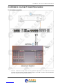
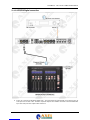
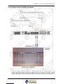
21 APPENDIX G - FALCON XT CONNECTION EXAMPLE .................................................................................... 97
21.1.1 Analog connection ......................................................................................................................................................... 97
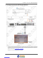
21.1.2 AES/EBU Digital connection......................................................................................................................................... 98
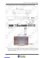
21.1.3 Analog connection and two transmitters ....................................................................................................................... 99
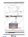
21.1.4 Analog Connection and an RDS Encoder (SideChain)................................................................................................ 100
21.1.5 Analog Connection and an Axel Technology RDS encoder (SideChain) ..................................................................... 101
21.1.6 Analog Connection and an Axel Technology RDS encoder (Loop-Through) .............................................................. 102
21.1.7 Analog Connection and a RDS Encoder (Loop-Through) ........................................................................................... 103
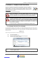
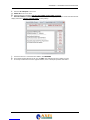
22 APPENDIX H – FIRMWARE UPDATE PROCEDURE ...................................................................................... 104
22.1 PREPARING THE DEVICE FOR UPGRADING ............................................................................................. 104
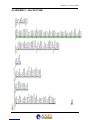
23 APPENDIX I – FALCON XT MIB ....................................................................................................................... 106
24 TECHNICAL SPECIFICATION - FALCON XT .................................................................................................. 107
25 WEEE Directive – Informativa RAEE .............................................................................................................. 108
26 GUARANTEE .................................................................................................................................................... 110
27 DECLARATION OF ROHS CONFORMITY ....................................................................................................... 110
28 FINAL NOTES AND AXEL TECHNOLOGY CONTACT DETAILS ................................................................... 111
| INTRODUCTION 4

ENG
1. INTRODUCTION
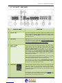
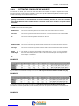
1.1 FALCON AUDIO PROCESSOR – VERSIONE AVAILABLE
CODE#
MODEL
COMMERCIAL DESCRIPTION
NOTES
A106360000
FALCON 3i
4-Band Digital FM Audio Processor with MPX stereo generator.
Analog and digital inputs and outputs and double MPX output.
MPX Split.
AGC, equalizer and speech detector, final limiter
drive and brilliance control.
4 GPIn and 4 GPOut, Rs232 serial
port and USB. Remote control software.
Available
option RDS
Encoder
A106370000
FALCON VS
5-
Band Digital FM Audio Processor, MPX stereo generator,
multiband AGC, stereo enhancer, brilliance control, lookahead
limiter, expander, and overdrive.
Audio changeover, MPX and
Analog/Digital I/O, double MPX output. MPX Split.
Four GP
inputs and four GP outputs. USB and Serial port. Remote control
software.
Available
Option:
LAN Interface
RDS Encoder
A106380000
FALCON XT
5-Band Digital FM-
Audio Processor, MPX stereo generator,
multiband AGC, superbass, stereo enhancer, overdrive,
brilliance control, lookahead limiter, audio changeover, analog,
digital and MPX IN/OUT. MPX Split. Ethernet. SNMP agent Web
Server, GPS interface. Four GP inputs and four GP outputs.
Remote control software.
Available
option RDS
Encoder
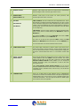
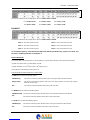
1.2 OPTION AVAILABLE FOR FALCON AUDIO PROCESSOR SERIE
CODE#
MODEL
COMMERCIAL DESCRIPTION
NOTES
A106360300
F-RDS
Digital RDS/RBDS en
coder. Static service generation: 60
programmable PS messages for Datasets, RadioText,
Alternative Frequency (AF), Traffic Program (TP), Traffic
Announcement (TA), EON, M/S, DI, CT, PI, PTY, PIN. Two
available datasets interchangeable via remote control.
UECP SPB490 compliant.
Available for
all Falcon
models
A106370300
F_VS-LAN
Optional Ethernet port for LAN-
type connections (TCP/IP
and UDP) and RS232 connection (ASCII Parser) for Falcon
VS only.
For Falcon VS
only
1.3 USE OF THIS MANUAL
This manual is for the Falcon XT. Certain features may be altered without prior notice.
| INTRODUCTION 5

ENG
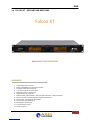
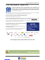
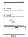
1.4 FALCON XT – DEPLIANT AND BROCHURE
Falcon XT
BROADCAST AUDIO PROCESSOR
HIGHLIGHTS
1. 5-Band Digital Audio Processor
2. Analog and AES/EBU input and output over XLR
3. Automatic Audio Input Changeover
4. 2 composite outputs and 2 AUX inputs
5. Mpx Power Control - ITU-R BS.412
6. Digital RDS Encoder, 2 Dataset
7. Multiband AGC, Speech Detector, 3-Band Eq, Stereo Enhancer, Limiter Lookahead
8. Brilliance Control, Expander, Overdrive, Superbass Harmonizer
9. Ethernet, Usb, 2 Serials Rs232, GPIn/GPOut
10. Gps Interface, NTP, SNMP Agent
11. Management via Web Page
12. Front headphone output
13. Hardware bypass
| INTRODUCTION 6

ENG
MAIN DESCRIPTION
Falcon XT is a Digital Audio Processor, a Stereo Generator and an RDS encoder, all in a single device, specifically
designed for the market of broadcast FM radio, Web Radio and Satellite.
The Falcon XT audio processor is based on DSP dedicated technology, with a 5-band audio processing architecture.
The Stereo Generator is fully digital, and can create a perfect Multiplex signal. Falcon XT, can be completed with a RDS
Encoder also fully digital DSP-based. Falcon XT allows to create your own soundprint, unique and unmistakable.
Be recognized today in the crowded world of broadcasters in FM, DVB-T or in the boundless world of the web has now
become very complicated, in a market where competition does not forgive mistakes. If the broadcaster does not want to
have the same soundprint of all radio stations, Falcon XT is the tools that stand out in this tangle of media.
Falcon XT provides the broadcaster even more demanding, extremely sophisticated audio features and high-level
standard: 5-band control compression, dual-band power AGC, three-band EQ and Brightness control. The parameterized
Stereo Enhancer command provide to the radio station sound, the spacing effect and large stereo horizon openings. The
control of the phases of mono audio signals, makes the voice sound more natural, the Expander control allows to
minimize the background or unwanted noise, while the Overdrive and the SuperBass dealing to make the sound more
important on low and very low frequencies, creating an impressive effect of loudness. In addition, the SuperBass
Harmonizer controls the distortion of the bass sound/low frequency, compared to their clipping, creating a sound impact
unmistakable, increasing the energy transmitted by the low frequency and making listening much more pleasant than
other audio processors. The two distinct Final Limiter drive, one broadband and one dedicated only to low frequencies,
maximize the presence of the sound, always maintaining a pleasant audio listening. Falcon XT makes the sound of any
single broadcaster unique, without creating a sound too artificially colored, that in time could be confused and become
tiring to be listen to.
The soundprint of each broadcaster can be created from one of ten preset audio files already on Falcon XT, from rock to
classical, country, talk show, or preset audio while preserving the original sound, enhance the character and the unique
details. It is possible to recall a preset using ASCII protocol serial / ethernet port or via GPIn logic state.
The Composite Clipper installed in the Stereo Generator provides the highest level of modulation, while the 'MPX Power
Control allow to use the processor in full compliance with the ITU-R BS.412 about a density reduction while maintaining
the same level of deviation. In order to calibrate and set up correctly the audio network, a digital tone generator with
variable sample frequency and amplitude is available on Analog, Digital and MPX outputs.
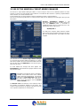
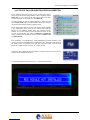
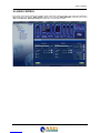
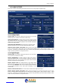
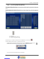
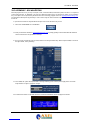
The Falcon XT front panel has two large LCD displays, the first LCD shows the whole process input and output from the
audio processor, including the amount of intervention on each single compressor band, the limiting introduced by the
multiband limiter, the AGC level, input and output levels of audio sources analog, digital and MPX. The second display
shows all Falcon XT parameters such as preset on the air, RDS station name, GP In and GP Out status. Again on the
front panel there is a headphone output for monitoring the audio process introduced by the Falcon XT. So it’s simple to
hear the difference between the original audio and the processed one.
The internal RDS encoder available as an option, provides two DataSet, each with a wide range of services including
static programmable PS 60 messages, 16 RadioText messages, Alternative Frequency (AF) to receive the best
frequency as a function of 'coverage area, the Traffic Program (TP) / Traffic Announcement (TA) to listen to traffic
information and functions such as EON, M/S, DI, CT, PI, PTY, PIN. The switching between the DataSet can occur by
serial commands, GPIO or TCP/IP from a radio automation system. The RDS encoder complies with UECP SPB490.
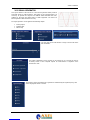
The connectivity of Falcon XT is complete and manifold. The rear panel contains XLR connectors for connection of the
inputs and outputs in analog and digital AES/EBU. As regards the part MPX are available two outputs individually
buffered and independent for the signal MPX+RDS, plus two additional inputs AUX (SCA) with different functionality. An
AUX input (SCA) expressly intended use of external RDS encoder, while a second input is able to switch the audio from
another processor MPX to create a subnet managed by the automation system. All outputs are equipped with hardware
bypass in case of fault of the apparatus.
For remote connections are available an Ethernet TCP/IP port, a RS232 serial port, a USB port and a connection port
GPIO with optocouplers and open collector representing the operating states and alarms. Falcon XT can be controlled
remotely via Windows-based client software or through a common http pages thanks to the web server. Universal power
supply 90-264Vac 47-63Hz to operate in any region of the world Falcon XT occupies 1 rack unit 19 "
| INTRODUCTION 7

ENG
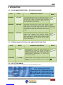
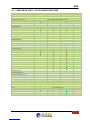
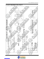
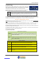
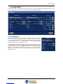
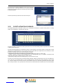
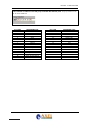
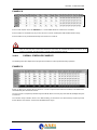
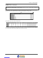
1.5 COMPARISON TABLE - FALCON AUDIO PROCESSOR
General Features
Falcon 3i
Falcon VS
Falcon XT
Note
Price List / MSRP
Audio processor band management
4
5
5
Audio process architecture
24Bit-120Mhz DSP-Based audio process
Stereo Generator – MPX Encoder
RDS Encoder
by option
by option
by option
Input and Output
Analog XLR In/Out
Digital AES/EBU XLR In/Out
2 BNC MPX Out and 1 BNC AUX IN
Hardware bypass I/O XLR/XLR–BNC/BNC
MPX Split Mode
Audio Management
Band management
4
5
5
3-Band Equalizer
Remote preset changer
Final Limiter Drive
Test tone generator
Brilliance control
Double band AGC (LO/HI)
AGC control
AGC power control
-
Audio Fault input changeover
-
MPX ITU-R BS.412 Control
-
Stereo Enhancer
-
Limiter LookAhead mode
-
Expander (noise reduction)
-
Overdrive power control
-
Super Bass control
-
Super Bass Harmonizer
-
-
Final Main Band Limiter Drive
-
-
Final Low Band Limiter drive
-
-
Preset clock-based manager
-
-
Remote Control
GPIO Connector – Type
SubD 15p HD - 4x GP In opto coupled, 4x GP Out Open Collector opto isolated
USB
1x USB – B Type EMI Filtered
Serial
1x Rs232 EMI Filtered
Software Remoter
Ethernet Port /Web Server
-
by option
Parser ASCII protocol via TCP/IP UDP/IP
-
by option
| INTRODUCTION 8

ENG
1 SAFETY WARNINGS / ISTRUZIONI PER LA SICUREZZA
SAFETY WARNINGS
CONSIGNES DE SÉCURITÉ IMPORTANTES
ISTRUZIONI IMPORTANTI PER LA SICUREZZA
WICHTIGE SICHERHEITSHINWEISE
INSTRUCCIONES IMPORTANTES DE SEGURIDAD
(Rel. 2.0)
1.1 FOREWORD
For your own safety and to avoid invalidation of the warranty all text marked with these Warning Symbols
should be read carefully.
Information in this manual is subject to change without notice and does not represent a commitment on the part of the
vendor.
The manufacturer shall not be liable for any loss or damage whatsoever arising from the use of information or any error
contained in this manual, or through any mis-operation or fault in hardware contained in the product.
It is recommended that all maintenance and service on the product should be carried out by the manufacturer or its
authorised agents. The manufacturer cannot accept any liability whatsoever for any loss or damage caused by service,
maintenance or repair by unauthorised personnel.
| SAFETY WARNINGS / ISTRUZIONI PER LA SICUREZZA - 9

ENG
2 SAFETY WARNINGS
The installation and servicing instructions in this manual are for use by qualified personnel only.
-
Read All Instructions. All safety and operating instructions must be read before operating the product. They also
must be retained for future reference, as it contains a number of useful hints for determining the best combination of
equipment settings for Yr particular application.
-
Heed All Warnings. All warnings on the product and those listed in the operating instructions must be adhered to.
-
Heat. This product must be situated away from any heat sources such as radiators or other products (including
power amplifiers or transmitters) that produce heat.
-
Power Sources. This product must be operated from the type of power source indicated on the marking label and in
the installation instructions. If you are not sure of the type of power supplied to your facility, consult your local power
company. Make sure the AC main voltage corresponds to that indicated in the technical specifications. If a different
voltage (ex. 110/115 VAC) is available, open the equipment closure and set the voltage switch on the main supply
circuit, located behind the AC socket
-
Power Cord Protection. Power supply cords must be routed so that they are not likely to be walked on nor pinched
by items placed upon or against them. Pay particular attention to the cords at AC wall plugs and convenience
receptacles, and at the point where the cord plugs into the product
-
Use only with a cart, stand, tripod, bracket, or table specified by the manufacturer, or sold with the apparatus. When
a cart is used, use caution when moving the cart/apparatus combination to avoid injury from tip-over.
-
Lightning. For added protection for this product during a lightning storm, or when it is left unattended and unused for
long periods of time, unplug it from the AC wall outlet and the audio connections. This will prevent damage to the
product due to lightning and power line surges
-
Installation. Configuration and installation should only be carried out by a competent installation engineer
-
Cabling. Using high quality wires, well protected. Make sure the cable integrity.
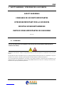
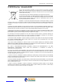
This symbol alerts you to the presence of dangerous voltage inside the closure – voltage which
may be sufficien
t to constitute a risk of shock. Do not perform any servicing other than that
contained in the operating instructions. Refer all servicing to qualified personnel
The exclamation point within an equilateral triangle is intended to alert the user to the presence of
important operating and maintenance (servicing) instructions in the literature accompanying the
appliance.
Do not change the voltage setting or replace the mains fuse without first turning the unit off
and unplugging the mains cord
Make sure the AC main voltage corresponds to that indicated in the technical specifications.
THIS APPARATUS MUST BE EARTHED !
To avoid risk of fire use the correct value fuse, as indicated on the label stuck on the right
side of the unit.
This apparatus uses a single pole mains switch and does therefore not separate the unit
completely from the mains power. To completely separate from mains power (in the event of
danger) unplug mains power cord. As the MAINS plug is the disconnect device, the
disconnect device shall remain readily operable.
| SAFETY WARNINGS - 10

ENG
3 CONSIGNES DE SÉCURITÉ IMPORTANTES
-
Lire ces consignes
-
Conserver ces consignes
-
Observer tous les avertissements
-
Suivre toutes les consignes
-
Ne pas utiliser cet appareil à proximité de l’eau
-
Ne pas obstruer les ouvertures de ventilation. Installer en respectant les consignes du fabricant
-
Ne pas installer à proximité d'une source de chaleur telle qu'un radiateur, une bouche de chaleur, un poêle ou
d'autres appareils (dont les amplificateurs) produisant de la chaleur.
-
Ne pas annuler la sécurité de la fiche de terre, la troisième branche est destinée à la sécurité. Si la fiche fournie
ne s'adapte pas à la prise électrique, demander à un électricien de remplacer la prise hors normes.
-
Protéger le cordon d'alimentation afin que personne ne marche dessus et que rien ne le pince, en particulier aux
fiches, aux prises de courant et au point de sortie de l’appareil
-
Utiliser uniquement les accessoires spécifiés par le fabricant
-
Utiliser uniquement avec un chariot, un support ou une table spécifié par le fabricant ou vendu avec l’appareil. Si
un chariot est utilisé, déplacer l’ensemble chariot–
appareil avec précaution afin de ne pas le renverser, ce qui
pourrait entraîner des blessures
-
Débrancher l’appareil pendant les orages ou quand il ne sera pas utilisé pendant longtemps.
-
Confier toute réparation à du personnel qualifié. Des réparations sont nécessaires si l’appareil est endommagé
d’une façon que
lconque, par exemple: cordon ou prise d’alimentation endommagé, liquide renversé ou objet tombé
à l’intérieur de l’appareil, exposition de l’appareil à la pluie ou à l’humidité, appareil qui ne marche pas normalement
ou que l’on a fait tomber.
-
NE PAS exposer cet appareil aux égouttures et aux éclaboussements. Ne pas poser des objets contenant de
l'eau, comme des vases, sur l'appareil
Ce symbole indique la présence d'une tension dangereuse dans l'appareil constituant un risque de
choc électrique.
Ce symbole indique que la documentation fournie avec l'appareil contient des instructions
d'utilisation et d'entretien importantes.
Avant de modifier le commutateur de changement de tension ou replacer le fusible il faut
débrancher l’appareil de la prise électrique. Pendant son usage, l’appareil doit etre branchee à la
prise de terre
Utiliser le fusible principal AC avec le valeur qui est indiquée sur l'étiquette collée sur le coffret.
Assurez-vous que la tension principale AC correspond à celle indiquée dans les spécifications
techniques.
L’interrupteur d’alimentation interrompt un pôle du réseau d’alimentation excepté le conducteur
de terre de protection. En cas de danger, debrancher le cordon d'alimentation. Parce que la prise
du réseau de alimentation est utilisée comme dispositif de déconnexion, ce dispositif doit
demeuré aisément accessible
| CONSIGNES DE SÉCURITÉ IMPORTANTES - 11

ENG
4 ISTRUZIONI IMPORTANTI PER LA SICUREZZA
-
Leggere le presenti istruzioni
-
Conservare queste istruzioni
-
Osservare tutte le avvertenze
-
Seguire scrupolosamente tutte le istruzioni
-
Non usare questo apparecchio in prossimità di acqua
-
Non ostruire alcuna apertura per il raffreddamento. Installare l’apparecchio seguendo le istruzioni
-
Non installare l'apparecchio accanto a fonti di calore quali radiatori, aperture per l'afflusso di aria calda, forni o
altri apparecchi (amplificatori inclusi) che generino calore
-
Non rimuovere il terminale di connessione a terra sul cordone di alimentazione: esso ha lo scopo di tutelare
l’incolumità dell’utilizzatore. Se la spina in dotazione non si adatta alla presa di corrente, rivolgersi ad un elettricista
per far eseguire le modifiche necessarie.
-
Evitare di calpestare il cavo di alimentazione o di comprimerlo, specialmente in corrispondenza della spina e del
punto di inserzione sull’apparato.
-
Utilizzare solo dispositivi di collegamento e gli accessori specificati dal produttore.
-
Utilizzare l’apparecchio solo con un carrello, un sostegno, una staffa o un tavolo di tipo specificato dal produttore o
venduto insieme all’apparecchio. Se si utilizza un carrello, fare attenzione negli spostamenti per evitare infortuni
causati da ribaltamenti del carrello stesso.
-
Scollegare l’apparecchio dalla presa di corrente durante i temporali o quando inutilizzato a lungo
-
Per qualsiasi intervento, rivolgersi a personale di assistenza qualificato. È’ necessario intervenire sull’apparecchio
ogniqualvolta si verificano danneggiamenti di qualsiasi natura. Ad esempio, la spina o il cavo di alimentazione sono
danneggiati, è entrato liquido nell’apparecchio o sono caduti oggetti su di esso, l’apparecchio è stato esposto alla
pioggia o all’umidità, non funziona normalmente o è caduto.
-
Non esporre a sgocciolamenti o spruzzi. Non appoggiare sull'apparecchio oggetti pieni di liquidi, ad esempio vasi
da fiori.
Questo simbolo indica la presenza di alta tensione all'interno dell'apparecchio, che comporta rischi
di scossa elettrica.
Questo simbolo indica la presenza di istruzioni importanti per l'uso e la manutenzione nella
documentazione in dotazione all'apparecchio.
Non sostituire il fusibile o cambiare la tensione di alimentazione senza aver prima scollegato il
cordone di alimentazione. L’APPARATO DEVE ESSERE CONNESSO A TERRA.
Sostituire il fusibile generale con uno di identico valore, come indicato sulla etichetta applicata
sul mobile dell’apparato
Assicurarsi che la tensione di rete corrisponda a quella per la quale è configurato
l’apparecchio
Questo apparato utilizza un interruttore di alimentazione di tipo unipolare e l’isolamento dalla
rete elettrica non è pertanto completo. Per ottenere un isolamento totale (ad esempio in caso di
pericolo), scollegare il cordone di alimentazione. Inoltre, poichè la spina di alimentazione è
utilizzata come dispositivo di sezionamento, essa deve restare facilmente raggiungibile
| ISTRUZIONI IMPORTANTI PER LA SICUREZZA - 12

ENG
5 WICHTIGE SICHERHEITSHINWEISE
-
Diese Hinweise LESEN
-
Diese Hinweise AUFHEBEN
-
Alle Warnhinweise BEACHTEN
-
Alle Anweisungen BEFOLGEN
-
Dieses Gerät NICHT in der Nähe von Wasser verwenden
-
KEINE Lüftungsöffnungen verdecken. Gemäß den Anweisungen des Herstellers einbauen
-
Nicht in der Nähe von Wärmequellen, wie Heizkörpern, Raumheizungen, Herden oder anderen Geräten
(einschließlich Verstärkern) installieren, die Wärme erzeugen
-
Die Schutzfunktion des Schukosteckers NICHT umgehen. Bei Steckern für die USA gibt es polarisierte Stecker,
bei denen ein Leiter breiter als der andere ist; US-Stecker mit Erdung verfügen über einen dritten Schutzleiter. Bei
diesen Steckerausführungen dient der breitere Leiter bzw. der Schutzleiter Ihrer Sicherheit. Wenn der mitgelieferte
Stecker nicht in die Steckdose passt, einen Elektriker mit dem Austauschen der veralteten Steckdose beauftragen
-
VERHINDERN, dass das Netzkabel gequetscht oder darauf getreten wird, insbesondere im Bereich der Stecker,
Netzsteckdosen und an der Austrittsstelle vom Gerät
-
NUR das vom Hersteller angegebene Zubehör und entsprechende Zusatzgeräte verwenden.
-
NUR in Verbindung mit einem vom Hersteller angegebenen oder mit dem Gerät verkauften Transportwagen, Stand,
Stativ, Träger oder Tisch verwenden. Wenn ein Transportwagen verwendet wird, beim Verschieben der
Transportwagen-Geräte- Einheit vorsichtig vorgehen, um Verletzungen durch Umkippen
-
Das Netzkabel dieses Geräts während Gewittern oder bei längeren Stillstandszeiten aus der Steckdose
ABZIEHEN.
-
Alle Reparatur- und Wartungsarbeiten von qualifiziertem Kundendienstpersonal DURCHFÜHREN LASSEN.
Kundendienst ist erforderlich, wenn das Gerät auf irgendwelche Weise beschädigt wurde, z.B. wenn das Netzkabel
oder der Netzstecker beschädigt wurden, wenn Flüssigkeiten in das Gerät verschüttet wurden oder Fremdkörper
hin
einfielen, wenn das Gerät Regen oder Feuchtigkeit ausgesetzt war, nicht normal funktioniert oder fallen gelassen
wurde.
-
Dieses Gerät vor Tropf- und Spritzwasser SCHÜTZEN. KEINE mit Wasser gefüllten Gegenstände wie zum
Beispiel Vasen auf das Gerät STELLEN.
Dieses Symbol zeigt an, dass gefährliche Spannungswerte, die ein Stromschlagrisiko darstellen,
innerhalb dieses Geräts auftreten.
Dieses Symbol zeigt an, dass das diesem Gerät beiliegende Handbuch wichtige Betriebs- und
Wartungsanweisungen enthält.
Vor Änderung der Netzspannung oder Sicherungswechsel Netzkabel trennen.
Das Gerät muss für den Betrieb geerdet werden.
Hauptsicherung nur mit einer gleichwertigen austauschen
(s. entsprechende Etikette).
Vor Einschalten Netzspannungseinstellung am Gerät überprüfen bzw. anpassen.
| WICHTIGE SICHERHEITSHINWEISE - 13


ENG
6 INSTRUCCIONES IMPORTANTES DE SEGURIDAD
-
LEA estas instrucciones
-
CONSERVE estas instrucciones
-
PRESTE ATENCION a todas las advertencias.
-
SIGA todas las instrucciones
-
NO utilice este aparato cerca del agua
-
NO obstruya ninguna de las aberturas de ventilación.Instálese según lo indicado en las instrucciones del
fabricante
-
No instale el aparato cerca de fuentes de calor tales como radiadores, registros de calefacción, estufas u otros
aparatos (incluyendo amplificadores) que produzcan calor
-
NO anule la función de seguridad del enchufe polarizado o con clavija de puesta a tierra. Un enchufe polarizado
tiene dos patas, una más ancha que la otra. Un enchufe con puesta a tierra tiene dos patas y una tercera clavija con
puesta a tierra. La pata más ancha o la tercera clavija se proporciona para su seguridad. Si el toma corriente no es
del tipo apropiado para el enchufe, consulte a un electricista para que sustituya el toma corriente de estilo anticuado
-
PROTEJA el cable eléctrico para evitar que personas lo pisen o estrujen, particularmente en sus enchufes, en los
toma corrientes y en el punto en el cual sale del aparato
-
UTILICE únicamente los accesorios especificados por el fabricante
-
UTILICESE únicamente con un carro, pedestal, escuadra o mesa del tipo especificado por el fabricante o vendido
con el aparato. Si se usa un carro, el mismo debe moverse con sumo cuidado para evitar que se vuelque con el
aparato
-
DESENCHUFE el aparato durante las tormentas eléctricas, o si no va a ser utilizado por un lapso prolongado.
-
TODA reparación debe ser llevada a cabo por técnicos calificados. El aparato requiere reparación si ha sufrido
cualquier tipo de daño, incluyendo los daños al cordón o enchufe eléctrico, si se derrama líquido sobre el aparato o
si caen objetos en su interior, si ha sido expuesto a la lluvia o la humedad, si no funciona de modo normal, o si se ha
caído.
-
NO exponga este aparato a chorros o salpicaduras de líquidos. NO coloque objetos llenos con líquido, tales como
floreros, sobre el aparato.
Este símbolo indica que la unidad contiene niveles de voltaje peligrosos que representan un riesgo
de choques eléctricos.
Este símbolo indica que la literatura que acompaña a esta unidad contiene instrucciones
importantes de funcionamiento y mantenimiento.
Antes de cambiar la alimentacion de voltaje o de cambiar el fusible, desconecte el cable de
alimentacion. Para reducir el riesgo de descargas electricas, esta unidad debe ser conectada a
tierra.
Remplaze el fusible con lo mismo, que corresponde a lo indicado en el panel del equipo.
Antes de encender, controlar que la linea de alimentacion de voltaje corresponda a la indicada
| INSTRUCCIONES IMPORTANTES DE SEGURIDAD - 15


UNPACKING AND INSPECTION
7 UNPACKING AND INSPECTION
Your equipment was packed carefully at the factory in a container designed to protect the unit during shipment.
Nevertheless, we recommend making a careful inspection of the shipping carton and the contents for any signs of
physical damage.
Damage & Claims
If damage is evident, do not discard the container or packing material. Contact your carrier immediately to file a claim for
damages. Customarily, the carrier requires you, the consignee, to make all damage claims. It will be helpful to retain the
shipping documents and the waybill number.
Save all packing materials! If You should ever have to ship the unti (e.g. for servicing), it is best to ship it in the
original carton with its packing materials because both the carton and packing material have been carefully
designed to protect the unit.
Under normal conditions no user maintenance or calibration are required. Internal links and preset controls may be set to
configure the unit during installation. Any service work required should be carried out by qualified service
personnel only.
We are able to offer further product support through our worldwide network of approved dealers and service agents.
To help us provide the most efficient service please would you keep a record of the unit serial
number, and date and place of purchase to be quoted in any communic
ation regarding this
product.
The actual equipment Serial Number is indicated on the silver label stuck on the rear panel of the equipment closure.
Tools And Equipment Needed
Only standard technician’s tools are required to install this equipment.
| UNPACKING AND INSPECTION - 17

FIRST INSTALLATION RECOMMENDATIONS
8 FIRST INSTALLATION RECOMMENDATIONS
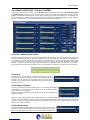
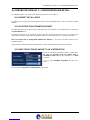
8.1 POWER SUPPLY CABLE
A power supply cable of approx. 2 mt length is supplied with the device, which has a moulded IEC plug attached – this is
a legal requirement.
The type of plug for the power supply depends on the country in which it is delivered.
If for any reason, you need to use this appliance with a different plug, you should use the following wiring guidelines in
replacing the existing plug with the new one:
Earth
Green, or green and yellow
Neutral (N)
Blue
Live (L)
Brown
Supply cables should be laid in such a manner that one does not step or walk on them. They should not be squashed by
any objects.
THIS EQUIPMENT MUST BE EARTHED.
The chassis is always connected to mains earth to ensure your safety: check your mains wiring and earthing before
switching on.
8.2 AC MAINS VOLTAGE SETTING (230 V / 115 V)
BE SURE THAT THE UNIT IS SET TO THE CORRECT MAINS/LINE VOLTAGE FOR YOUR
COUNTRY BEFORE PLUGGING IT INTO THE WALL OUTLET !
The actual Mains voltage is indicated on the label stuck on the equipment closure. Should the type of power at the
operation location not be known, please contact your dealer or electricity company.
If, for some reason, the unit is to be operated at a mains input voltage which is different to that as supplied, you need to
switch the voltage selector on the right side of the unit. You also need to replace the AC main fuse, according to
information provided on the external label or on the Technical Specifications table at the end of this user manual.
CAUTION:
TO REDUCE THE RISK OF ELECTRICAL SHOCK, ALWAYS DISCONNECT THE AC
MAINS CABLE BEFORE ALTERING THE CHANGE-
OVER SWITCH. NO USER SERVICEABLE
PARTS INSIDE. REFER SERVICING TO QUALIFIED SERVICE PERSONNEL.
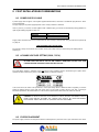
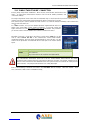
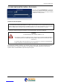
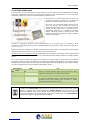
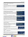
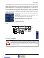
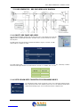
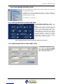
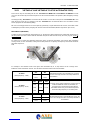
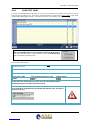
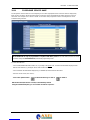
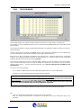
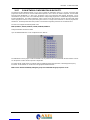
8.3 FUSE REPLACEMENT
The power supply socket has an integral fuse drawer containing the AC power fuse and a spare, both of the same value.
| FIRST INSTALLATION RECOMMENDATIONS - 18

FIRST INSTALLATION RECOMMENDATIONS
BEFORE REPLACING THE POWER FUSE, MAKE SURE YOU HAVE THE RIGHT TYPE OF FUSE FOR
THE VOLTAGE TO BE PROTECTED.
USING WRONG FUSE TYPE WILL RESULT IN INSUFFICIENT PROTECTION.
Make sure that the power is switched off and the power cable is disconnected from the equipment.
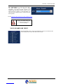
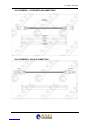
a. Open the upper iron cover using a screwdriver.
b. Replace the fuse located at the internal position – Power supply Type-1
c. Replace the fuse located at the internal position – Power supply Type-2
Perform the set-up under static control conditions. Static charges are likely to completely destroy one or
more of the CMOS semiconductors employed in the unit. Static damage will not be covered under
warranty.
| FIRST INSTALLATION RECOMMENDATIONS - 19

FIRST INSTALLATION RECOMMENDATIONS
Basic damage prevention consists of minimizing generation, discharging any accumulated static charge
on your body and preventing that discharge from being sent to or through any electronic component.
Uninsulated dangerous voltage are inside the enclosure, voltage that may be sufficient to constitute a
risk of shock.
Always disconnect to AC Mains before removing the top cover
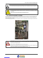
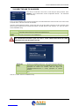
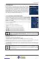
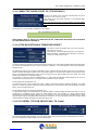
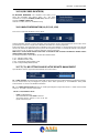
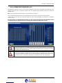
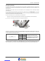
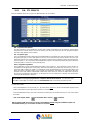
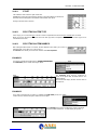
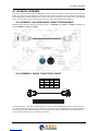
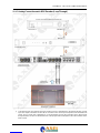
8.4 PROTECTION AGAINST LIGHTNING
When the upper iron cover is removed, a plastic transparent cover helps the user safety, to avoid from flashlight coming
from the switching power supply. After the power cord has been disconnected some parts of the power supply remain
electrically loaded for a lot of time.
Axel Technology suggest to don’t touch never this parts, and it is not responsible for human flash light or electrical burns.
Should the device be put out of action due to being struck by lightning or excess voltage, disconnect it
from the power supply without delay. Do not reconnect until the device has been checked. If in doubt
contact the technical support service.
Make sure there is suitable lighting protection to protect the device.
Alternatively you should disconnect all connectors from the device during a storm or when the device
is going to be unsupervised or not used for a longer period of time.
These measures will protect against damage by lightning or excess voltage.
| FIRST INSTALLATION RECOMMENDATIONS - 20
La pagina si sta caricando...
La pagina si sta caricando...
La pagina si sta caricando...
La pagina si sta caricando...
La pagina si sta caricando...
La pagina si sta caricando...
La pagina si sta caricando...
La pagina si sta caricando...
La pagina si sta caricando...
La pagina si sta caricando...
La pagina si sta caricando...
La pagina si sta caricando...
La pagina si sta caricando...
La pagina si sta caricando...
La pagina si sta caricando...
La pagina si sta caricando...
La pagina si sta caricando...
La pagina si sta caricando...
La pagina si sta caricando...
La pagina si sta caricando...
La pagina si sta caricando...
La pagina si sta caricando...
La pagina si sta caricando...
La pagina si sta caricando...
La pagina si sta caricando...
La pagina si sta caricando...
La pagina si sta caricando...
La pagina si sta caricando...
La pagina si sta caricando...
La pagina si sta caricando...
La pagina si sta caricando...
La pagina si sta caricando...
La pagina si sta caricando...
La pagina si sta caricando...
La pagina si sta caricando...
La pagina si sta caricando...
La pagina si sta caricando...
La pagina si sta caricando...
La pagina si sta caricando...
La pagina si sta caricando...
La pagina si sta caricando...
La pagina si sta caricando...
La pagina si sta caricando...
La pagina si sta caricando...
La pagina si sta caricando...
La pagina si sta caricando...
La pagina si sta caricando...
La pagina si sta caricando...
La pagina si sta caricando...
La pagina si sta caricando...
La pagina si sta caricando...
La pagina si sta caricando...
La pagina si sta caricando...
La pagina si sta caricando...
La pagina si sta caricando...
La pagina si sta caricando...
La pagina si sta caricando...
La pagina si sta caricando...
La pagina si sta caricando...
La pagina si sta caricando...
La pagina si sta caricando...
La pagina si sta caricando...
La pagina si sta caricando...
La pagina si sta caricando...
La pagina si sta caricando...
La pagina si sta caricando...
La pagina si sta caricando...
La pagina si sta caricando...
La pagina si sta caricando...
La pagina si sta caricando...
La pagina si sta caricando...
La pagina si sta caricando...
La pagina si sta caricando...
La pagina si sta caricando...
La pagina si sta caricando...
La pagina si sta caricando...
La pagina si sta caricando...
La pagina si sta caricando...
La pagina si sta caricando...
La pagina si sta caricando...
La pagina si sta caricando...
La pagina si sta caricando...
La pagina si sta caricando...
La pagina si sta caricando...
La pagina si sta caricando...
La pagina si sta caricando...
La pagina si sta caricando...
La pagina si sta caricando...
La pagina si sta caricando...
La pagina si sta caricando...
La pagina si sta caricando...
-
 1
1
-
 2
2
-
 3
3
-
 4
4
-
 5
5
-
 6
6
-
 7
7
-
 8
8
-
 9
9
-
 10
10
-
 11
11
-
 12
12
-
 13
13
-
 14
14
-
 15
15
-
 16
16
-
 17
17
-
 18
18
-
 19
19
-
 20
20
-
 21
21
-
 22
22
-
 23
23
-
 24
24
-
 25
25
-
 26
26
-
 27
27
-
 28
28
-
 29
29
-
 30
30
-
 31
31
-
 32
32
-
 33
33
-
 34
34
-
 35
35
-
 36
36
-
 37
37
-
 38
38
-
 39
39
-
 40
40
-
 41
41
-
 42
42
-
 43
43
-
 44
44
-
 45
45
-
 46
46
-
 47
47
-
 48
48
-
 49
49
-
 50
50
-
 51
51
-
 52
52
-
 53
53
-
 54
54
-
 55
55
-
 56
56
-
 57
57
-
 58
58
-
 59
59
-
 60
60
-
 61
61
-
 62
62
-
 63
63
-
 64
64
-
 65
65
-
 66
66
-
 67
67
-
 68
68
-
 69
69
-
 70
70
-
 71
71
-
 72
72
-
 73
73
-
 74
74
-
 75
75
-
 76
76
-
 77
77
-
 78
78
-
 79
79
-
 80
80
-
 81
81
-
 82
82
-
 83
83
-
 84
84
-
 85
85
-
 86
86
-
 87
87
-
 88
88
-
 89
89
-
 90
90
-
 91
91
-
 92
92
-
 93
93
-
 94
94
-
 95
95
-
 96
96
-
 97
97
-
 98
98
-
 99
99
-
 100
100
-
 101
101
-
 102
102
-
 103
103
-
 104
104
-
 105
105
-
 106
106
-
 107
107
-
 108
108
-
 109
109
-
 110
110
-
 111
111


Axel Falcon VS Manuale utente
- Categoria
- Schede audio
- Tipo
- Manuale utente
in altre lingue
- English: Axel Falcon VS User manual
Documenti correlati


Altri documenti
-
Sangean MMR-99 Manuale utente
-
-
Lindy 38263 Manuale utente
-
AxelTech Fox 3 Manuale utente
-
Datalogic Falcon X4 Manuale utente
-
Genius FALCON M Manuale utente
-
-
Genius FALCON 5M 8M 424M Istruzioni per l'uso
-
-