
NEDERLANDS 3
ENGLISH 6
DEUTSCH 9
FRANÇAIS 12
ESPAÑOL 15
ITALIANO 18
Copyright © 2023 VETUS B.V. Schiedam Holland
Installatie- en gebruikershandleiding
Hydraulische boegschroef
Installation and user manual
Hydraulic bow thruster
Installations- und Benutzerhandbuch
Hydraulische Bugschraube
Manuel d’Installation et d’utilisation
Hélice d’étrave hydraulique
Manual de instalación y usuario
Hélice de proa hidráulico
Manuale d'installazione e d'uso
Elica di prua idraulico
Hydraulic bow thruster
120201.07
Installation and user manual
BOW55HMD - BOW95HMD - BOW160HMD
BOW230HMD - BOW310HMD -
BOWH410 - BOWH550

Installation and user manual Hydraulic bow thruster 55, 95, 160, 230, 310, 410, 550 kgf
2 120201.07
Boeg- en hekschroef
bedieningspanelen . . . . . . . . . . . . . 21
7 Hoofdafmetingen . . . . . . . . . . . . . . . 22
8 Hydraulische schema’s . . . . . . . . . . 23
Panneaux de commande d’hélice
d’étrave et de poupe . . . . . . . . . . . . 21
7 Dimensions principales. . . . . . . . . . 22
8 Schémas hydrauliques . . . . . . . . . . 23
Bow and stern thruster control
panels . . . . . . . . . . . . . . . . . . . . . . . . . . 21
7 Principal dimensions . . . . . . . . . . . . 22
8 Hydraulic diagrams . . . . . . . . . . . . . 23
Tableros de control para
la hélice de proa y de popa . . . . . . 21
7 Dimensiones principales . . . . . . . . 22
8 Esquemas hidráulicos . . . . . . . . . . . 23
Armaturenbrettern für Bug- und
Heckschrauben . . . . . . . . . . . . . . . . . 21
7 Hauptabmessungen . . . . . . . . . . . . 22
8 Hydraulische Schaltpläne. . . . . . . . 23
Pannelli di comando di eliche
di prua e poppa . . . . . . . . . . . . . . . . . 21
7 Dimensioni principali . . . . . . . . . . . 22
8 Schemi idraulici . . . . . . . . . . . . . . . . . 23
1 Veiligheid. . . . . . . . . . . . . . . . . . . . . . . . 3
2 Inleiding . . . . . . . . . . . . . . . . . . . . . . . . . 3
3 Gebruik. . . . . . . . . . . . . . . . . . . . . . . . . . 3
4 Installatie instructies . . . . . . . . . . . . . 4
5 Storingen . . . . . . . . . . . . . . . . . . . . . . . . 5
6 Technische gegevens. . . . . . . . . . . . . 5
Inhoud Content Inhalt
1 Safety . . . . . . . . . . . . . . . . . . . . . . . . . . . 6
2 Introduction . . . . . . . . . . . . . . . . . . . . . 6
3 Use . . . . . . . . . . . . . . . . . . . . . . . . . . . . . . 6
4 Installation instructions . . . . . . . . . . 7
5 Trouble shooting. . . . . . . . . . . . . . . . . 8
6 Technical data. . . . . . . . . . . . . . . . . . . . 8
1 Sicherheitsbestimmungen
. . . . . . . 9
2 Einleitung. . . . . . . . . . . . . . . . . . . . . . . . 9
3 Gebrauch . . . . . . . . . . . . . . . . . . . . . . . . 9
4 Installationsanleitung . . . . . . . . . . . 10
5 Störungen . . . . . . . . . . . . . . . . . . . . . . 11
6 Technische daten . . . . . . . . . . . . . . . 11
1 Sécurité
. . . . . . . . . . . . . . . . . . . . . . . . 12
2 Introduction . . . . . . . . . . . . . . . . . . . . 12
3 Emploi. . . . . . . . . . . . . . . . . . . . . . . . . . 12
4 Instructions de montage . . . . . . . . 13
5 Pannes. . . . . . . . . . . . . . . . . . . . . . . . . . 14
6 Renseignements techniques. . . . . 14
Sommaire Índice Indice
1 Seguridad . . . . . . . . . . . . . . . . . . . . . . 15
2 Introducción . . . . . . . . . . . . . . . . . . . . 15
3 Uso . . . . . . . . . . . . . . . . . . . . . . . . . . . . . 15
4 Instrucciones de instalación . . . . . 16
5 Fallos . . . . . . . . . . . . . . . . . . . . . . . . . . . 17
6 Especicaciones técnicas . . . . . . . . 17
1 Sicurezza . . . . . . . . . . . . . . . . . . . . . . . 18
2 Introduzione. . . . . . . . . . . . . . . . . . . . 18
3 Funzionamento . . . . . . . . . . . . . . . . . 18
4 Istruzioni di installazione . . . . . . . . 19
5 Guasti . . . . . . . . . . . . . . . . . . . . . . . . . . 20
6 Dati tecnici. . . . . . . . . . . . . . . . . . . . . . 20

Installation and user manual Hydraulic bow thruster 55, 95, 160, 230, 310, 410, 550 kgf
1 Veiligheid
Waarschuwingsaanduidingen
Indien van toepassing worden in deze handleiding in verband met
veiligheid de volgende waarschuwingsaanduidingen gebruikt:
Gevaar
Geeft aan dat er een groot potentieel gevaar aanwezig is dat ernstig
letsel of de dood tot gevolg kan hebben.
WaarschuWinG
Geeft aan dat er een potentieel gevaar aanwezig is dat letsel tot ge-
volg kan hebben.
voorzichtiG
Geeft aan dat de betreende bedieningsprocedures, handelingen,
enzovoort, letsel of fatale schade aan de machine tot gevolg kunnen
hebben. Sommige VOORZICHTIG-aanduidingen geven tevens aan
dat er een potentieel gevaar aanwezig is dat ernstig letsel of de dood
tot gevolg kan hebben.
Let op
Legt de nadruk op belangrijke procedures, omstandigheden, enzo-
voort.
Symbolen
Geeft aan dat de betreende handeling moet worden uit-
gevoerd.
Geeft aan dat een bepaalde handeling verboden is.
Deel deze veiligheidsinstructies met alle gebruikers.
Algemene regels en wetten met betrekking tot veiligheid en ter voor-
koming van ongelukken dienen altijd in acht te worden genomen.
2 Inleiding
Afhankelijk van de windvang, de waterverplaatsing en de vorm van
het onderwaterschip zal de door de boegschroef geleverde stuw-
kracht op ieder schip een verschillend resultaat geven.
De nominaal opgegeven stuwkracht is alleen haalbaar onder opti-
male omstandigheden; houdt daarom rekening met de volgende
factoren:
- Opbrengst en druk van de pomp moeten optimaal op de hydro-
motor zijn afgestemd.
- De wijze waarop de tunnelbuis aansluit op de scheepsromp is van
groot belang. Zie ‘Installatieinstructies’.
- Plaats in de tunnelbuis-openingen alleen dan spijlen indien dit
strikt noodzakelijk is (indien regelmatig in sterk vervuilde wateren
wordt gevaren).
- Indien spijlen worden toegepast neem dan de aanbevelingen in
het hoofdstuk ‘Installatieinstructies’ in acht.
Het gevolg geven aan de hierna volgende aanbevelingen zal resulte-
ren in een langere levensduur en in betere prestaties van uw boeg-
schroef.
- Laat de boegschroef nooit langdurig draaien; in verband met
warmteontwikkeling.
- Controleer tijdens varen of temperatuur van hydraulische olie niet
te hoog wordt (max. 100˚C).
- Voer regelmatig het aangegeven onderhoud uit.
3 Gebruik
Algemeen
- De boegschroef kan alleen gebruikt worden indien de hoofdmo-
tor, welke de hydraulische pomp aandrijft, in bedrijf is!
- De stuwkracht van de boegschroef is afhankelijk van:
- het motortoerental van de hoofdmotor
- het aantal ingeschakelde hydraulisch apparaten (bijvoorbeeld
gelijktijdig gebruik van zowel boegschroef als hekschroef)
- Afhankelijk van het type load-sensing-ventiel dat is toegepast,
dient de boegschroef bediend te worden met het daarvoor be-
stemde bedieningspaneel:
-1-step load-sensing-ventiel:
3-standen pookschakelaar: BPJE2 of BPJDE2, of keuzeschake-
laar: BPSE2
-2-step load-sensing-ventiel:
5-standen pookschakelaar: BPJ5 of BPJSTH5 of BPJ5D
Voorzichtig
Indien 2 bedieningspanelen zijn geïnstalleerd; bedien de
boegschroef dan nooit gelijktijdig vanaf beide panelen.
120201.07 3
NEDERLANDS

Installation and user manual Hydraulic bow thruster 55, 95, 160, 230, 310, 410, 550 kgf
4 120201.07
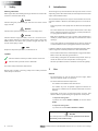
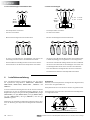
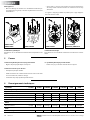
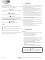
Hydromotor
De ruimte waarin de hydromotor van de boegschroef wordt opge-
steld dient droog en goed geventileerd te zijn.
De hydromotor kan in verschillende standen worden ingebouwd.
De hydromotor dient steeds boven het maximale niveau van het bil-
ge-water te worden opgesteld.
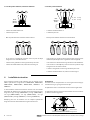
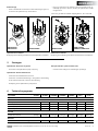
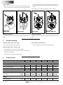
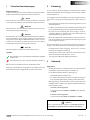
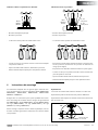
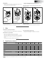
3-standen pookschakelaar, of keuzeschakelaar
• Schakel de hoofdschakelaar in.
• Schakel het paneel in.
- Met de pookschakelaar wordt het ventiel bediend.
- In de stand ‘L’ en ‘R’ blijft de pook niet staan. De pook zal altijd
terugveren naar de middenstand ‘C’.
- Schakel na het gebruik van de boegschroef het paneel uit.
- Schakel de hoofdschakelaar uit, indien U van boord gaat.
5-standen pookschakelaar
• Schakel de hoofdschakelaar in.
• Schakel het paneel in.
- Met de pookschakelaar wordt het ventiel bediend.
- In de stand ‘1L’ en ‘1R’ draait de boegschroef met ongeveer halve
stuwkracht (afhankelijk van de ingestelde loadsensingdruk).
- In de stand ‘2L’ en ‘2R’ draait de boegschroef met volle stuwkracht.
- In de stand ‘2L’ en ‘2R’ blijft de pook niet staan. De pook zal altijd
terugveren naar de stand ‘1L’ of ‘1R’.
- Schakel na het gebruik van de boegschroef het paneel uit.
- Schakel de hoofdschakelaar uit, indien U van boord gaat.
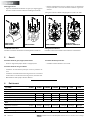
BPJE2
BPJDE2
(BPSE2)
L C R
BPJ5
BPJSTH5
BPJ5D
1L2L C 1R 2R
1L, 1R: 1e trap
2L, 2R: 2e trap
4 Installatie instructies
180º
Max. niveau
bilge-water
Deze installatie instructie geeft richtlijnen voor de inbouw van de
VETUS hydraulische boegschroeven ‘BOW55HMD’, ‘BOW95HMD’,
‘BOW160HMD’, ‘BOW230HMD’, ‘BOW310HMD’, ‘BOWH410’ en
‘BOWH550’.
In deze installatie instructie wordt alleen dat deel van de installatie
behandelt dat afwijkt van de installatie instructie behorende bij de
boegschroef type ‘55 kgf’ (‘BOW55HMD’), ‘95 kgf’ (‘BOW95HMD’),
‘160 kgf’ (‘BOW160HMD’), ‘230 kgf’ (‘BOW230HMD’), ‘310 kgf’
(‘BOW310HMD’), ‘410 kgf’ (‘BOWH410’) en ‘550 kgf’ (‘BOWH550’)
Raadpleeg dus voor de installatie van de complete hydraulische
boegschroef ook de desbetreende boegschroef-instructie.

Installation and user manual Hydraulic bow thruster 55, 95, 160, 230, 310, 410, 550 kgf
6 Technische gegevens
Type BOW : 55HMD 95HMD 160HMD 230HMD 310HMD H410 H550
Hydraulische motor
Type : Omkeerbare motor
Vermogen [kW] : 3,5 6,0 9,5 12,5 20 63 108
Toerental [omw/min] : 3000 4100 3300 1900 2000 3400 4300
Werkdruk [bar] : 165 230 250 230 225 350 450
Capaciteit [cm3/omw] : 4,2 4,2 7,0 16,8 26,4 24,0 35,6
Schroef
Stuwkracht nominaal : 550 N
(55 kgf)
950 N
(95 kgf)
1600 N
(160 kgf)
2300 N
(230 kgf)
3100 N
(310 kgf)
4100 N
(410 kgf)
5500 N
(550 kgf)
Gewicht
Excl. tunnelbuis, incl. staartstuk [kg] : 7 8,5 15 22 31 40 45
120201.07 5
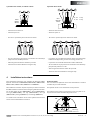
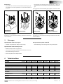
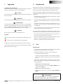
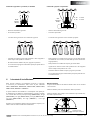
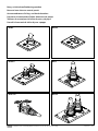
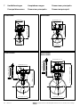
Eindmontage
• Vet de schroefdraad van de bouten in met ‘outboard gear grease’ *)
en monteer de hydromotor op de tussenflens.
BOW55HMD
BOW95HMD BOW160HMD BOW230HMD
BOW310HMD,
BOWH410, BOWH550
5 Storingen
Hydraulische installatie
Raadpleeg de handleiding 'Installation manual Hydraulic installation'
Het hydraulische systeem verliest olie.
- Controleer alle leidingen en verbindingen op lekkage.
NEDERLANDS
• Draai ter controle met de hand de schroef rond, deze moet ge-
makkelijk zijn rond te draaien, waarbij de hydromotoras wordt
meegenomen.
*) Een zeer geschikt vet is VETUS ‘Shipping Grease’, Art. code: VSG.
Elektrische installatie
Raadpleeg de handleiding ‘Installation manual Electrical installation'
Hydromotor draait (te) Iangzaam.
- Toerental van de hydraulische pomp is (te) laag.
Hydromotor draait helemaal niet.
- Controleer of hoofdschakelaar ‘Aan’ staat.
- Controleer of stuurstroomzekering is doorgebrand. Kortsluiting
in het stuurstroomcircuit; controleer de bedrading.
- Aandrijving van de hydraulische pomp defect.

Installation and user manual Hydraulic bow thruster 55, 95, 160, 230, 310, 410, 550 kgf
1 Safety
Warning indications
Where applicable, the following warning indications are used in this
manual in connection with safety:
DanGer
Indicates that great potential danger exists that can lead to serious
injury or death.
WarninG
Indicates that a potential danger that can lead to injury exists.
caution
Indicates that the usage procedures, actions etc. concerned can re-
sult in serious damage to or destruction of the engine. Some CAU-
TION indications also advise that a potential danger exists that can
lead to serious injury or death.
note
Emphasises important procedures, circumstances etc.
Symbols
Indicates that the relevant procedure must be carried out.
Indicates that a particular action is forbidden.
Share these safety instructions with all users.
General rules and laws concerning safety and accident prevention
must always be observed.
2 Introduction
The thrust given by the bow thruster will vary from vessel to vessel
depending on the effect of the wind, the water displacement and the
shape of the underwater hull.
The nominal thrust quoted can only be achieved under the most fa-
vourable conditions. Therefore, the following factors are to be obser-
ved:
- Flow and pressure of the pump must be attuned to the hydraulic
motor.
- The actual method of connecting the thrust tunnel to the ship’s
hull is of utmost importance for the best possible performance.
See paragraph ‘installation instructions’.
- Only when absolutely necessary (e.g. when sailing frequently in
muddy or polluted waters) grids may be installed to the tunnel
openings.
- In case such grid bars are being tted, please observe closely the
recommendations made in paragraph ‘installation instructions’.
Compliance with the recommendations that follow hereafter, will re-
sult in a longer life and better performance of the bow thruster:
- Never run the bow thruster continuously for a long period of time.
With a view to the internally generated heat.
- Check during sailing that the maximum temperature of the hy-
draulic oil doesn’t exceed a temperature of 100 degrees C.
- All of the specied maintenance should be carried out regularly.
3 Use
General
- The bow thruster can only be used if the main engine, which
drives the hydraulic pump, is in operation.
- The thrust of the bow thruster depends on:
- the number of revolutions of the main motor
- the number of pieces of hydraulic equipment switched on
(for instance simultaneous use of both bow thruster and stern
thruster)
- Depending on the type of load-sensing-valve used, the bow
thruster must be operated using the appropriate control panel:
-1-step load-sensing-valve:
3-position lever switch: BPJE2 or BPJDE2, or selector switch:
BPSE2
-2-step load-sensing-valve:
5-position lever switch: BPJ5 or BPJSTH5 or BPJ5D
caution
If 2 control panels are installed never operate the bow thruster
from both panels simultaneously.
6 120201.07
ENGLISH

Installation and user manual Hydraulic bow thruster 55, 95, 160, 230, 310, 410, 550 kgf 120201.07 7
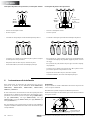
Hydraulic motor
The room where the hydraulic motor of the bow thruster is installed
should be dry and well ventilated.
The hydraulic motor can be installed in various positions.
The hydraulic motor must be positioned in such a way that it is al-
ways well clear from the maximum bilge water level.
3-position lever switch, or selector switch
- Switch the main switch on.
- Switch the panel on.
- The valve is operated by means of the lever switch.
- The lever will not stay in positions ‘L’ and ‘R’. The lever will always
jump back to the middle position ‘C’.
- After using the bow thruster switch the panel o.
- Switch the main switch o when leaving the ship.
5-position lever switch
- Switch the main switch on.
- Switch the panel on.
- The valve is operated by means of the lever switch.
- In positions ‘1L’ and ‘1R’ the bow thruster works at approximately
half the thrust (depending on the load-sensing pressure set).
- In positions ‘2L’ and ‘2R’ the bow thruster works at full thrust.
- The lever will not stay in positions ‘2L’ and ‘2R’. The lever will always
jump back to position ‘1L’ or ‘1R’.
- After using the bow thruster switch the panel o.
- Switch the main switch o when leaving the ship.
BPJE2
BPJDE2
(BPSE2)
L C R
BPJ5
BPJSTH5
BPJ5D
1L2L C 1R 2R
1L, 1R: 1e trap
2L, 2R: 2e trap
4 Installation instructions
180º
Max. bilge
water level
These installation instructions give guidelines for fitting the VETUS
hydraulic bow thrusters ‘BOW55HMD’, ‘BOW95HMD’, ‘BOW160HMD’,
‘BOW230HMD’ , ‘BOW310HM’D, ‘BOWH410’ and ‘BOWH550’.
This installation instruction explains only that part of the installation
that differs from the installation instruction going with the bow thrus-
ters ‘55 kgf’ model ‘55 kgf’ (‘BOW55HMD’), ‘95 kgf’ (‘BOW95HMD’),
‘160 kgf’ (‘BOW160HMD’), ‘230 kgf’ (‘BOW230HMD’), ‘310 kgf’
(‘BOW310HMD’), ‘410 kgf’ (‘BOWH410’) and ‘550 kgf’ (‘BOWH550’)
So consult for the installation of the entire hydraulic bow thruster
also the relevant bow thruster instruction.
ENGLISH

Installation and user manual Hydraulic bow thruster 55, 95, 160, 230, 310, 410, 550 kgf
6 Technical data
Type BOW : 55HMD 95HMD 160HMD 230HMD 310HMD H410 H550
Hydraulic motor
Type : Reversible motor
Rated output [kW] : 3.5 6.0 9.5 12.5 20 63 108
No. of revolutions [rpm] : 3000 4100 3300 1900 2000 3400 4300
Operating pressure [bar] : 165 230 250 230 225 350 450
Capacity [cm3/rev.] : 4.2 4.2 7.0 16.8 26.4 24.0 35.6
Propeller
Rated thrust :
550 N
(55 kgf)
(121 lbf)
950 N
(95 kgf)
(209 lbf)
1600 N
(160 kgf)
(352 lbf)
2300 N
(230 kgf)
(507 lbf)
3100 N
(310 kgf)
(683 lbf)
4100 N
(410 kgf)
(904 lbf)
5500 N
(550 kgf)
(1212 lbf)
Weight
Excl. thrust-tunnel : 7 kg
(15 lbs)
8.5 kg
(18 lbs)
15 kg
(33 lbs)
22 kg
(49 lbs)
31 kg
(68 lbs)
40
(88 lbs)
45
(99 lbs)
8 120201.07
Final assembly
• Grease the threads of the fastenings bolts with ‘outboard gear
grease’ and install the hydraulic motor to the intermediate ange.
BOW55HMD
BOW95HMD BOW160HMD BOW230HMD
BOW310HMD,
BOWH410, BOWH550
5 Trouble shooting
Hydraulic installation
Consult the installation manual 'Installation manual Hydraulic instal-
lation'
The hydraulic system looses oil.
- Check all tubing and connections for possible leakage.
• For a rst check, turn the propeller by hand, it should turn easi-
ly, whilst being connected to the output spindle of the hydraulic
motor.
*) A suitable grease is VETUS ‘Shipping Grease’, Art. code: VSG.
Electrical installation
Consult the installation manual ‘Installation manual Electrical instal-
lation'
Hydraulic motor rotates (too) slowly.
- Speed of the hydraulic pump is (too) low.
Hydraulic motor does not rotate at all.
- Check whether the main switch is in position ‘ON’.
- Check whether the control circuit fuse is blown. Control circuit is
shortened, check wiring.
- Transmission of the hydraulic pump is faulty.
ENGLISH

Installation and user manual Hydraulic bow thruster 55, 95, 160, 230, 310, 410, 550 kgf
1 Sicherheitsbestimmungen
Gefahrenhinweise
In dieser Anleitung werden, soweit zutreend, die folgenden Warn-
hinweise im Zusammenhang mit der Sicherheit verwendet:
Gefahr
Weist darauf hin, dass ein hohes Potenzial an Gefahren vorhanden
ist, die schwere Verletzungen oder den Tod zur Folge haben können.
WarnunG
Weist darauf hin, dass ein Potenzial an Gefahren vorhanden ist, die
Verletzungen zur Folge haben können.
vorsicht
Weist darauf hin, dass die betreenden Bedienungsschritte, Maßnah-
men usw. Verletzungen oder schwere Schäden an der Maschine zur
Folge haben können. Manche VORSICHT-Hinweise weisen auch da-
rauf hin, dass ein Potenzial an Gefahren vorhanden ist, die schwere
Verletzungen oder den Tod zur Folge haben können.
achtunG
Besonderer Hinweis auf wichtige Schritte, Umstände usw.
Symbole
Weist darauf hin, dass die betreende Handlung durchgeführt
werden muss.
Weist darauf hin, dass eine bestimmte Handlung verboten ist.
Geben Sie diese Sicherheitshinweise an alle Benutzer weiter.
Allgemein geltende Gesetze und Richtlinien zum Thema Sicherheit
und zur Vermeidung von Unglücksfällen sind stets zu beachten.
2 Einleitung
Je nach Takelage, Wasserverdrängung und Unterwasser-schifform
führt die Antriebskraft durch die Bugschraube auf jedem Schiff zu
anderen Ergebnissen.
Die angegebene Nennantriebskraft ist nur unter optimalen Umstän-
den erreichbar; deswegen sind folgende Faktoren immer zu beach-
ten:
- Ertrag und Druck der Pumpe sollen optimal abgestimmt sein auf
den Hydraulikmotor.
- Die Weise worauf der Tunnel zum Schiffsbug angeschloßen wird
ist von größter Bedeutung; siehe Paragraph ‘Einbauanleitung’.
- Nur wenn absolut notwendig (z.B. wenn ständig in stark ver-
schmutzten Gewässern gefahren wird), können Gitterstäbe zu
den Tunnelöffnungen montiert werden.
- Wenn schon Gitterstäbe notwendigerweise montiert werden, so
sind die Vorschriften des Paragraphes ‘Einbauanleitung’ mit größ-
ter Genauigkeit zu befolgen.
Ein genaues Befolgen der nachstehenden Hinweise bürgt für eine
längere Lebensdauer und für bessere Leistung Ihres Bugschraubes.
- Die Bugschraube niemals langjährig drehen lassen, in Zusam-
menhang mit der Wärmeentwicklung.
- Kontrollieren Sie während des Fahrens ob die Temperatur des hy-
draulischen Öl nicht zu höh wird (max. 100°C).
- Jede angegebene Wartung sorgfältig durchführen.
3 Gebrauch
Allgemeines
- Die Bugschraube kann nur benutzt werden, wenn der die hydrau-
lische Pumpe antreibende Hauptmotor in Betrieb ist.
- Die Schubkraft der Bugschraube ist abhängig von:
- der Motordrehzahl des Hauptmotors
- der Anzahl eingeschalteter hydraulischer Apparate (beispiels-
weise gleichzeitige Benutzung von Bug- und Heckschraube)
- Abhängig vom Typ des verwendeten Load-Sensing-Ventils, muss
die Bugschraube mit dem jeweils dafür bestimmten Bedienungs-
paneel bedient werden:
-1-Schritt-Load-Sensing-Ventil:
3-Stand-Steuerknüppel: BPJE2 oder BPJDE2, oder Wahlschal-
ter: BPSE2
-2-Schritt-Load-Sensing-Ventil:
5-Stand-Steuerknüppel: BPJ5 oder BPJSTH5 oder BPJ5D
vorsicht
Wenn 2 Armaturenbretter eingebaut sind, die Bugschraube nie
gleichzeitig von beiden Armaturen-brettern aus bedienen.
6 Technical data
Type BOW : 55HMD 95HMD 160HMD 230HMD 310HMD H410 H550
Hydraulic motor
Type : Reversible motor
Rated output [kW] : 3.5 6.0 9.5 12.5 20 63 108
No. of revolutions [rpm] : 3000 4100 3300 1900 2000 3400 4300
Operating pressure [bar] : 165 230 250 230 225 350 450
Capacity [cm3/rev.] : 4.2 4.2 7.0 16.8 26.4 24.0 35.6
Propeller
Rated thrust :
550 N
(55 kgf)
(121 lbf)
950 N
(95 kgf)
(209 lbf)
1600 N
(160 kgf)
(352 lbf)
2300 N
(230 kgf)
(507 lbf)
3100 N
(310 kgf)
(683 lbf)
4100 N
(410 kgf)
(904 lbf)
5500 N
(550 kgf)
(1212 lbf)
Weight
Excl. thrust-tunnel : 7 kg
(15 lbs)
8.5 kg
(18 lbs)
15 kg
(33 lbs)
22 kg
(49 lbs)
31 kg
(68 lbs)
40
(88 lbs)
45
(99 lbs)
120201.07 9
DEUTSCH

Installation and user manual Hydraulic bow thruster 55, 95, 160, 230, 310, 410, 550 kgf
10 120201.07
Hydromotor
Der Platz, an dem der Hydromotor der Bugschraube aufgestellt wird,
muss trocken und gut belüftet sein.
Der Hydromotor kann in verschiedenen Ständen eingebaut werden.
Der Hydromotor muss immer über dem Höchststand des Bilgenwas-
sers aufgestellt werden.
3-Stand-Steuerknüppel oder Wahlschalter
- Den Hauptschalter einschalten.
- Das Paneel einschalten.
- Mit dem Steuerknüppel wird das Ventil bedient.
- Im Stand ‘L’ und ‘R’ bleibt der Steuerknüppel nicht stehen. Der
Steuerknüppel federt immer in den Mittelstand ‘C’ zurück.
- Nach dem Gebrauch der Bugschraube das Paneel ausschalten.
- Vor dem Verlassen des Bootes den Hauptschalter ausschalten.
5-Stand-Steuerknüppel
- Den Hauptschalter einschalten.
- Das Paneel einschalten.
- Mit dem Steuerknüppel wird das Ventil bedient.
- Im Stand ‘1L’ und ‘1R’ dreht die Bugschraube mit ungefähr halber
Schubkraft (abhängig vom eingestellten Load-Sensing-Druck).
- Im Stand ‘2L’ und ‘2R’ dreht die Bugschraube mit voller Schubkraft.
- Im Stand ‘2L’ und ‘2R’ bleibt der Steuerknüppel nicht stehen. Der
Steuerknüppel federt immer in den Stand ‘1L’ oder ‘1R’ zurück.
- Nach dem Gebrauch der Bugschraube das Paneel ausschalten.
- Vor dem Verlassen des Bootes den Hauptschalter ausschalten.
BPJE2
BPJDE2
(BPSE2)
L C R
BPJ5
BPJSTH5
BPJ5D
1L2L C 1R 2R
1L, 1R: 1. Schritt
2L, 2R: 2. Schritt
4 Installationsanleitung
180º
Max. Stand
Bilgewasser
Diese Installationsanleitung enthält Richtlinien für den Einbau
der hydraulischen Bugschrauben ‘BOW55HMD’, ‘BOW95HMD’,
‘BOW160HMD’, ‘BOW230HMD’, ‘BOW310HMD’ , ‘BOWH410’ und
‘BOWH550’.
In dieser Installationsanleitung wird nur auf den Teil der Installation
eingegangen, der von der Installationsanleitung abweicht, die zur
Bugschraube der Typen ‘55 kgf’ model ‘55 kgf’ (‘BOW55HMD’), ‘95 kgf’
(‘BOW95HMD’), ‘160 kgf’ (‘BOW160HMD’), ‘230 kgf’ (‘BOW230HMD’),
‘310 kgf’ (‘BOW310HMD’), ‘410 kgf’ (‘BOWH410’) und ‘550 kgf’
(‘BOWH550’) gehört.
Zur Montage der vollständigen hydraulischen Bugschraube ist daher
auch die Anleitung der entsprechenden Bugschraube hinzuzuzie-
hen.
DEUTSCH

Installation and user manual Hydraulic bow thruster 55, 95, 160, 230, 310, 410, 550 kgf
6 Technische daten
Typ BOW : 55HMD 95HMD 160HMD 230HMD 310HMD H410 H550
Hydraulikmotor
Typ : umkehrbarer Motor
Leistung [kW] : 3,5 6,0 9,5 12,5 20 63 108
Drehzahl [U/min] : 3000 4100 3300 1900 2000 3400 4300
Betriebsdruck [bar] : 165 230 250 230 225 350 450
Kapazität [cm3 pro Umdrehung] : 4,2 4,2 7,0 16,8 26,4 24,0 35,6
Schraube
Staudruck nominal : 550 N
(55 kgf)
950 N
(95 kgf)
1600 N
(160 kgf)
2300 N
(230 kgf)
3100 N
(310 kgf)
4100 N
(410 kgf)
5500 N
(550 kgf)
Gewicht
Exkl. Tunnelröhre inkl. Endstück [kg] : 7 8,5 15 22 31 40 45
120201.07 11
Endmontage
• Das Gewinde der Schrauben mit Getriebefett (outboard gear gre-
ase) schmieren und den Hydromotor auf den Zwischenflansch
montieren.
BOW55HMD
BOW95HMD BOW160HMD BOW230HMD
BOW310HMD,
BOWH410, BOWH550
5 Störungen
Hydraulische installation
Konsultieren Sie die Installationsanleitung 'Installation manual Hyd-
raulic installation'
Das hydraulische System verliert Öl
- Alle Verbindungen und Leitungen auf Leckage überprüfen.
• Zur Kontrolle die Schraube mit der Hand drehen. Sie muss sich
einfach drehen lassen und dabei die Hydromotorwelle mitbewe-
gen.
*)Ein geeignetes Fett ist das VETUS „Shipping Grease“, Artikelcode: VSG.
Elektrische Installation
Konsultieren Sie die Installationsanleitung ‘Installation manual Elec-
trical installation'
Hydraulikmotor dreht (zu) langsam.
- Drehzahl des hydraulischen Pumpe ist (zu) niedrig.
Hydraulikmotor dreht überhaupt nicht.
- Wurde der Hauptschalter eingeschaltet?
- Steuerstromsicherung beansprucht? Kurzschlulß im Steuerstrom-
kreislauf. Bedrahtung kontrolieren.
- Antrieb der hydraulischen Pumpe defekt.
DEUTSCH

Installation and user manual Hydraulic bow thruster 55, 95, 160, 230, 310, 410, 550 kgf
1 Sécurité
Messages d’avertissement
Dans ce manuel, les indications d’avertissement suivantes sont utili-
sées au besoin en rapport avec la sécurité :
DanGer
Indique qu’il existe un danger potentiel important pouvant entrainer
des lésions graves ou même la mort.
avertissement
Indique qu’il existe un danger potentiel pouvant entrainer des lé-
sions.
pruDence
Indique que les procédures de maniement, manipulations etc.
concernées, peuvent entraîner des lésions ou des dommages fatals
à la machine. Certaines indications de PRUDENCE indiquent égale-
ment qu’il existe un danger potentiel pouvant entrainer des lésions
graves ou même la mort.
attention
Insiste sur les procédures importantes, les conditions d’utilisation et
cætera.
Symboles
Indique que l’opération en question doit être eectuée.
Indique qu’une opération spécique est interdite.
Partagez ces consignes de sécurité avec tous les utilisateurs.
Les réglementations et la législation générales en matière de sécurité
et de prévention d’accidents doivent être respectées à tout moment
2 Introduction
Selon la prise de vent, le déplacement d’eau et la forme des oeuvres
vives, la force de propulsion fournie par l’hélice d’étrave entraînera
un résultat différent sur chaque bateau.
La force de propulsion nominale indiquée n’est réalisable que dans
des circonstances optimales. Tenez alors compte des facteurs sui-
vants:
- La puissance et la pression du pompe doivent optimalement être
mis au point au moteur hydraulique.
- Le procédé d’assemblage de la tuyère à la coque est d’une très
grande importance. Voir les instructions d’installation.
- En cas de nécessité absolue (navigation plus ou moins perma-
nente dans des eaux très pollués), il est admissible d’installer des
grilles dans les ouvertures de la tuyère.
- Observez strictement les recommendations du chapitre instruc-
tions d’installation en cas demontage des grilles.
Donner suite aux recommandations cimentionnées, permettra une
durée de vie prolongée ainsi qu’un meilleur fonctionnement de l’hé-
lice d’étrave.
- Ne jamais faire opérer l’hélice d’étrave longtemps, vu la produc-
tion de chaleur.
- Contrôler la température de l’huile hyraulique pendant la naviga-
tion. Elle ne doit pas excéder les 100°C.
- Suivre les instructions de l’entretien avec soin.
3 Emploi
Généralités
- L’hélice d’étrave ne peut être utilisée que si le moteur principal,
qui entraîne la pompe hydraulique, fonctionne.
- La force de propulsion de l’hélice d’étrave dépend des éléments
suivants:
- le régime du moteur principal
- le nombre d’appareils hydrauliques branchés (par exemple
l’usage simultané de l’hélice d’étrave et de l’hélice de poupe)
- Selon le type de valve de détection de charge (load-sensing) uti-
lisé, l’hélice d’étrave devra être pilotée avec le panneau de com-
mande destiné à cet effet.
-valve de détection de charge à 1 phase
Sélecteur à levier à 3 positions: BPJE2 ou BPJDE2, ou sélecteur:
BPSE2
-valve de détection de charge à 2 phases
Sélecteur à levier à 5 positions : BPJ5 ou BPJSTH5 ou BPJ5D
pruDence
Si 2 tableaux de commande sont installés, ne commandez jama-
is l’hélice d’étrave à partir des deux tableaux en même temps.
12 120201.07
FRANÇAIS

Installation and user manual Hydraulic bow thruster 55, 95, 160, 230, 310, 410, 550 kgf 120201.07 13
Hydromoteur
Le local où est installée l’hélice d’étrave doit être sec et bien aéré.
L’hydromoteur peut être monté dans des positions diérentes.
L’hydromoteur doit toujours être installé au-dessus du niveau maxi-
mal de l’eau de cale.
Sélecteur à levier à 3 positions ou sélecteur
• Brancher l’interrupteur principal.
• Brancher le panneau.
- Le sélecteur à levier permet de commander la valve.
- Le levier ne reste pas en position ‘L’ et ‘R’. Le levier revient toujours
à la position centrale ‘C’.
- Après avoir utilisé l’hélice d’étrave, débrancher le panneau.
- Débranchez l’interrupteur principal si vous quittez le bateau.
Sélecteur à levier à 5 positions
• Brancher l’interrupteur principal.
• Brancher le panneau.
- Le sélecteur à levier permet de commander la valve.
- En position ‘1L’ et ‘1R’, l’hélice d’étrave fonctionne à environ la moi-
tié de la puissance (en fonction de la pression de détection de
charge qui est réglée).
- En position ‘2L’ et ‘2R’, l’hélice d’étrave fonctionne à plein régime.
- Le levier ne reste pas en position ‘2L’ et ‘2R’. Le levier reviendra tou-
jours aux positions ‘1L’ ou ‘1R’.
- Après avoir utilisé l’hélice d’étrave, débrancher le panneau.
- Débranchez l’interrupteur principal si vous quittez le bateau.
BPJE2
BPJDE2
(BPSE2)
L C R
BPJ5
BPJSTH5
BPJ5D
1L2L C 1R 2R
1L, 1R:
1ère phase
2L, 2R:
2ème phase
4 Instructions de montage
180º
Niveau de léau
de cale max.
Ces instructions indiquent dans les grandes lignes comment mon-
ter les modèles d’hélices d’étrave hydrauliques VETUS ‘BOW55HMD’,
‘BOW95HMD’, ‘BOW160HMD’, ‘BOW230HMD’, ‘BOW310HMD’.
‘BOWH410’ et ‘BOWH550’.
Ne figure dans ces instructions que la partie qui diffère des instruc-
tions de montage des modèles d’hélices de type ‘55 kgf’ model ‘55
kgf’ (‘BOW55HMD’), ‘95 kgf’ (‘BOW95HMD’), ‘160 kgf’ (‘BOW160HMD’),
‘230 kgf’ (‘BOW230HMD’), ‘310 kgf’ (‘BOW310HMD’), ‘410 kgf’
(‘BOWH410’) et ‘550 kgf’ (‘BOWH550’).
Pour le montage complet de l’hélice d’étrave hydraulique, vous de-
vrez donc consulter également les instructions concernant le modèle
correspondant.
FRANÇAIS

Installation and user manual Hydraulic bow thruster 55, 95, 160, 230, 310, 410, 550 kgf
6 Renseignements techniques
Type BOW : 55HMD 95HMD 160HMD 230HMD 310HMD H410 H550
Moteur hydraulique
Type : moteur réversible
Puissance disponible [kW] : 3,5 6,0 9,5 12,5 20 63 108
Tours minute [t/min] : 3000 4100 3300 1900 2000 3400 4300
Pression d’opération [bar] : 165 230 250 230 225 350 450
Capacité [cm3/rev] : 4,2 4,2 7,0 16,8 26,4 24,0 35,6
Hélice
Poussée nominal : 550 N
(55 kgf)
950 N
(95 kgf)
1600 N
(160 kgf)
2300 N
(230 kgf)
3100 N
(310 kgf)
4100 N
(410 kgf)
5500 N
(550 kgf)
Poids
Sans tuyère [kg] : 7 8,5 15 22 31 40 45
14 120201.07
Montage final
• Graisser le letage des boulons avec du lubriant au lithium spé-
cial (outboard gear grease) et monter l’hydromoteur sur la bride
intermédiaire.
BOW55HMD
BOW95HMD BOW160HMD BOW230HMD
BOW310HMD,
BOWH410, BOWH550
5 Pannes
Installation hydraulique
Konsultieren Sie das Handbuch 'Installation manual Hydraulic instal-
lation'
Le système hydraulique perd de l'huile.
- Vérier s'il n'y a pas de fuite de l'huile dans les tuyaux.
• Visser l’hélice à la main pour vérier son bon fonctionnement :
elle doit pouvoir tourner facilement en entraînant l’axe de l’hy-
dromoteur.
*) La graisse « Shipping » VETUS est parfaite pour ce type d'applica-
tion. Code d'article : VSG.
Installation électrique
Konsultieren Sie das Handbuch ‘Installation manual Electrical instal-
lation'
Le moteur hydraulique tourne (trop) lentement.
- Régime du pompe hydraulique est trop bas.
Le moteur ne tourne pas du tout.
- Interrupteur principal sur ‘OFF’.
- Fusible du tableau de commande défectueux. Court-circuit dans
le circuit conducteur, vérier le câblage.
- Commande du pompe hydraulique défectueuse.
FRANÇAIS

Installation and user manual Hydraulic bow thruster 55, 95, 160, 230, 310, 410, 550 kgf
6 Renseignements techniques
Type BOW : 55HMD 95HMD 160HMD 230HMD 310HMD H410 H550
Moteur hydraulique
Type : moteur réversible
Puissance disponible [kW] : 3,5 6,0 9,5 12,5 20 63 108
Tours minute [t/min] : 3000 4100 3300 1900 2000 3400 4300
Pression d’opération [bar] : 165 230 250 230 225 350 450
Capacité [cm3/rev] : 4,2 4,2 7,0 16,8 26,4 24,0 35,6
Hélice
Poussée nominal : 550 N
(55 kgf)
950 N
(95 kgf)
1600 N
(160 kgf)
2300 N
(230 kgf)
3100 N
(310 kgf)
4100 N
(410 kgf)
5500 N
(550 kgf)
Poids
Sans tuyère [kg] : 7 8,5 15 22 31 40 45
1 Seguridad
Indicadores de advertencias
Cuando corresponda, se utilizan las siguientes indicaciones de adver-
tencia en este manual en relación con la seguridad:
peLiGro
Indica que existe un gran peligro potencial que puede causar graves
daños o la muerte.
aDvertencia
Indica la existencia de un peligro potencial que puede causar daños.
tenGa cuiDaDo
Indica que los procedimientos de uso, acciones, etc., correspondien-
tes pueden causar daños graves o romper el motor. Algunas indica-
ciones de TENGA CUIDADO también avisan de la existencia de un
peligro potencial que puede causar graves daños o la muerte.
atención
Destaca procesos o circunstancias importantes, etc.
Símbolos
Indica que el proceso correspondiente se debe llevar a cabo.
Indica que una acción determinada está prohibida.
Comparta estas instrucciones de seguridad con todos los usuarios.
Siempre deben respetarse las normas y leyes generales sobre seguri-
dad y prevención de accidentes.
2 Introducción
En función de la amurada, el desplazamiento de agua y la forma su-
bacuática de la embarcación, la fuerza de propulsión generada por la
hélice de proa dará un resultado distinto en cada embarcación.
La fuerza de propulsión nominal indicada únicamente se puede reali-
zar bajo circunstancias óptimas; por eso, tenga en cuenta los siguien-
tes factores:
- El rendimiento y la presión de la bomba del hidromotor se deben
ajustar con absoluta precisión.
- La manera como el conducto se conecta al casco de la embarca-
ción es de suma importancia. Véanse las ‘Instrucciones de insta-
lación’.
- Coloque en las aberturas del conducto solamente barras si es es-
trictamente necesario (cuando se navega regularmente en aguas
contaminadas).
- Si se colocan barras, tenga en cuenta las recomendaciones del ca-
pítulo principal ‘Instrucciones de instalación’.
La observación de las siguientes recomendaciones resultará en una
más prolongada vida útil y mejores prestaciones de su hélice de proa.
- Nunca dejar funcionar prolongadamente la hélice de proa; en re-
lación con el desarrollo térmico en el motor.
- Durante la navegación, controle que la temperatura del aceite hi-
dráulico no alcance temperaturas altas (max. 100˚C).
- Realizar con regularidad el mantenimiento indicado.
3 Uso
Generalidades
- ¡La hélice de proa solo se puede usar cuando el motor principal,
que propulsa la bomba hidráulica, está activado!
- El empuje de propulsión de la hélice de proa depende de:
- la velocidad del motor principal;
- el número de aparatos hidráulicos conectados (por ejemplo, el
uso sincrónico tanto de la hélice de proa como de la hélice de
popa).
- Según el tipo de válvula sensora de carga que se tenga en uso, la
hélice de proa debe ser manejada por medio del tablero de man-
do correspondiente:
-Válvula sensora de carga de 1 paso:
Interruptor de palanca de 3 posiciones: BPJE2 o BPJDE2, o Inte-
rruptor selector: BPSE2.
-Válvula sensora de carga de 2 pasos:
Interruptor de palanca de 5 posiciones: BPJ5 o BPJSTH5 o
BPJ5D.
tenGa cuiDaDo
Si están instalados dos tableros de mandos; nunca manejar si-
multáneamente desde ambos tableros la hélice de proa.
120201.07 15
ESPAÑOL

Installation and user manual Hydraulic bow thruster 55, 95, 160, 230, 310, 410, 550 kgf
16 120201.07
Hidromotor
El espacio donde se instala el hidromotor de la hélice de proa ha de
estar seco y bien ventilado.
El hidromotor se puede incorporar en diferentes posiciones.
El hidromotor siempre ha de instalarse por encima del nivel máximo
del agua de sentina.
Interruptor de palanca de 3 posiciones, o interruptor selector
• Conecte el interruptor central.
• Accione el panel.
- La válvula es manejada por medio del interruptor de palanca.
- La palanca no se queda en la posición ‘L’ y ‘R’. La palanca siempre
se debe reponer en la posición ‘C’.
- Después de usar la hélice de proa, desactive el panel.
- Si usted desembarca, desactive el interruptor principal.
Interruptor de palanca de 5 posiciones
• Conecte el interruptor central.
• Accione el panel.
- La válvula es manejada por medio del interruptor de palanca.
- En la posición ‘1L’ y ‘1R’, la hélice de proa gira aproximadamente
con la mitad del empuje de propulsión (según la presión sensora
de carga).
- En la posición ‘2L’ y ‘2R’, la hélice de proa gira con todo el empuje
de propulsión.
- La palanca no se queda en la posición ‘2L’ y ‘2R’. La palanca siem-
pre se debe reponer en la posición ‘1L’ o ‘1R’.
- Después de usar la hélice de proa, desactive el panel.
- Si usted desembarca, desactive el interruptor principal.
BPJE2
BPJDE2
(BPSE2)
L C R
BPJ5
BPJSTH5
BPJ5D
1L2L C 1R 2R
1L, 1R:
1era posición
2L, 2R:
2da posición
4 Instrucciones de instalación
180º
Nivel máximo del
agua de sentina
Estas instrucciones de instalación dan indicaciones para la incor-
poración de las hélices de proa hidráulicas VETUS ‘BOW55HMD’,
‘BOW95HMD’, ‘BOW160HMD’, ‘BOW230HMD’, ‘BOW310HMD’,
‘BOWH410’ y ‘BOWH550’.
En estas instrucciones de instalación se trata sólo aquella parte de la
instalación que es distinta de las instrucciones de instalación corres-
pondientes a la hélice de proa de los tipos ‘55 kgf’ (‘BOW55HMD’),
‘95 kgf’ (‘BOW95HMD’), ‘160 kgf’ (‘BOW160HMD’), ‘230 kgf’
(‘BOW230HMD’), ‘310 kgf’ (‘BOW310HMD’), ‘410 kgf’ (‘BOWH410’) Y
‘550 kgf’ (‘BOWH550’)
Por consiguiente, para la instalación de la hélice de proa hidráulica
completa consúltense también las instrucciones de la hélice de proa
correspondientes.
ESPAÑOL

Installation and user manual Hydraulic bow thruster 55, 95, 160, 230, 310, 410, 550 kgf
6 Especificaciones técnicas
Tipo BOW : 55HMD 95HMD 160HMD 230HMD 310HMD H410 H550
Motor hidráulico
Tipo : motor reversible
Potencia [kW] : 3,5 6,0 9,5 12,5 20 63 108
Número de revoluciones [rev/min] : 3000 4100 3300 1900 2000 3400 4300
Presión de trabajo [bar] : 165 230 250 230 225 350 450
Capacidad [cm3/por vuelta] : 4,2 4,2 7,0 16,8 26,4 24,0 35,6
Hélice
Fuerza de propulsión nominal : 550 N
(55 kgf)
950 N
(95 kgf)
1600 N
(160 kgf)
2300 N
(230 kgf)
3100 N
(310 kgf)
4100 N
(410 kgf)
5500 N
(550 kgf)
Peso
Excluido conducto [kg] : 7 8,5 15 22 31 40 45
120201.07 17
Montaje final
• Engrase la rosca de los tornillos con ‘outboard gear grease’ y mon-
te el hidromotor sobre la brida intermedia.
BOW55HMD
BOW95HMD BOW160HMD BOW230HMD
BOW310HMD,
BOWH410, BOWH550
5 Fallos
Instalación hidráulica
Consultar el manual 'Installation manual Hydraulic installation'
El sistema hidráulico pierde aceite.
- Asegure que no haya fugas en conductos ni conexiones.
• Efectúe el control girando con la mano la hélice, la que ha de po-
der girar con facilidad, llevando el eje del hidromotor.
*) Una grasa adecuada es VETUS Shipping Grease (Grasa náutica),
Código de art.: VSG.
Instalación eléctrica
Consultar el manual ‘Installation manual Electrical installation'
El hidromotor gira (muy) lentamente.
- El número de revoluciones de la bomba hidráulica está (muy) bajo.
El hidromotor no gira del todo.
- Revise que el interruptor principal esté ‘Encendido’.
- Revise que el fusible de la corriente de control no esté fundido.
Cortocircuito en el circuito de la corriente de control; revise el ca-
bleado.
- La propulsión de la bomba hidráulica está defectuosa.
ESPAÑOL

Installation and user manual Hydraulic bow thruster 55, 95, 160, 230, 310, 410, 550 kgf
1 Sicurezza
Indicazioni di avvertimento
Ove applicabile, in questo manuale vengono utilizzate le seguenti
indicazioni di avvertenza in relazione alla sicurezza:
pericoLo
Indica un potenziale pericolo che può essere causa di gravi infortuni
o di morte.
avvertimento
Indica un potenziale pericolo che può essere causa di infortuni.
cauteLa
Indica che le procedure di comando e le azioni eettuate possono
causare danni o danneggiare irrimediabilmente la macchina. Alcune
indicazione di CAUTELA segnalano anche potenziali pericoli che pos-
sono essere causa di gravi infortuni o di morte.
attenzione
Evidenzia procedure importanti, situazioni particolari, ecc.
Simboli
Indica che deve essere eettuata una determinata operazi-
one.
Indica che è vietato eettuare una determinata operazione.
Condividere queste istruzioni di sicurezza con tutti gli utenti.
Osservate sempre tutte le norme e disposizioni di legge relative alla
sicurezza ed alla prevenzione degli infortuni.
2 Introduzione
In base alla superficie laterale esposta al vento, alla stazza e alla for-
ma dell’opera viva, la propulsione generata dall’elica di prua darà un
risultato diverso su ogni imbarcazione.
La propulsione nominale è raggiungibile soltanto in condizioni otti-
mali; per questo bisogna tenere conto dei seguenti fattori:
- La mandata e la pressione della pompa devono essere regolati in
maniera ottimale sul motore principale.
- Il modo in cui il tunnel per elica si collega allo scafo dell’imbarcazi-
one è molto importante.Vedi ‘Istruzioni di installazione’.
- Se necessario, montare solo delle sbarre sulle aperture del tunnel
per l’elica (se si naviga regolarmente in acque molto sporche).
- Se si montano delle sbarre, accogliere le raccomandazioni riporta-
te nel capitolo ‘Istruzioni di installazione’.
Rispettando le seguenti raccomandazioni otterrete una maggiore
durata dell’elica e prestazioni migliori.
- Non fare girare mai l’elica di prua troppo a lungo; per motivi legati
allo sviluppo di calore nel motore.
- Durante la navigazione, controllare che la temperatura dell’olio
non salga eccessivamente (max. 100˚C).
- Eseguire regolarmente le operazioni di manutenzione.
3 Funzionamento
Generale
- L’elica di prua può essere utilizzata solo se il motore principale, che
alimenta la pompa idraulica, è in funzione!
- La forza propulsiva dell’elica di prua dipende da:
- il numero di giri del motore principale
- il numero degli apparecchi idraulici in funzione (ad esempio
uso contemporaneo dell’elica di prua e di poppa)
- Secondo il tipo di valvola load-sensing installata, l’elica di prua
deve essere governata con l’apposito pannello di comando:
-valvola load-sensing a stadio singolo:
comando a joystick a 3 posizioni: BPJE2 o BPJDE2, o selettore:
BPSE2.
-valvola load-sensing a doppio stadio:
comando a joystick a 5 posizioni: BPJ5 o BPJSTH5 o BPJ5D
cauteLa
Se sono stati installati due pannelli di comando: non comandare
l’elica contemporaneamente con tutti e due i pannelli.
18 120201.07
ITALIANO

Installation and user manual Hydraulic bow thruster 55, 95, 160, 230, 310, 410, 550 kgf 120201.07 19
Motore idraulico
Lo spazio di installazione del motore idraulico deve essere asciutto
e ben ventilato.
Il motore idraulico può essere installato in diverse posizioni.
Il motore idraulico deve sempre essere installato sopra il livello mas-
simo dell’acqua di sentina
Comando a joystick a 3 posizioni, o selettore
• Azionare l’interruttore generale.
• Accendere il pannello.
- La valvola viene governata con il comando a joystick.
- Il joystick non rimane inserito nelle posizioni ‘L’ ed ‘R’. Il joystick ri-
torna sempre nella posizione centrale ‘C’.
- Al termine dell’uso dell’elica di prua, spegnere il pannello.
- Si raccomanda di spegnere l’interruttore principale prima di lasci-
are l’imbarcazione.
Comando a joystick a 5 posizioni
• Azionare l’interruttore generale.
• Accendere il pannello.
- La valvola viene governata con il comando a joystick.
- Nelle posizioni ‘1L’ ed ‘1R’ l’elica di prua gira con una forza propul-
siva ridotta di circa la metà (a seconda della pressione di load sen-
sing impostata).
- Nelle posizioni ‘2L’ ed ‘2R’ l’elica di prua gira a tutta forza.
- Il joystick non rimane inserito nelle posizioni ‘2L’ e ‘2R’. Il joystick
ritorna sempre nella posizione ‘1L’ o ‘1R’.
- Al termine dell’uso dell’elica di prua, spegnere il pannello.
- Si raccomanda di spegnere l’interruttore principale prima di lasci-
are l’imbarcazione.
BPJE2
BPJDE2
(BPSE2)
L C R
BPJ5
BPJSTH5
BPJ5D
1L2L C 1R 2R
1L, 1R: 1° stadio
2L, 2R: 2° stadio
4 Istruzioni di installazione
180º
Livello massimo
dell’acqua di sentina
Nelle presenti istruzioni di installazione troverete le indicazio-
ni necessarie per l’installazione delle eliche di prua idrauliche
VETUS ‘BOW55HMD’, ‘BOW95HMD’, ‘BOW160HMD’, ‘BOW230HMD’,
‘BOW310HMD’, ‘BOWH410’ e ‘BOWH550’.
In queste istruzioni di installazione è contemplata solo quella par-
te dell’impianto che differisce dall’installazione secondo le istruzio-
ni a corredo delle eliche di prua tipo ‘55 kgf’ (‘BOW55HMD’), ‘95 kgf’
(‘BOW95HMD’), ‘160 kgf’ (‘BOW160HMD’), ‘230 kgf’ (‘BOW230HMD’),
‘310 kgf’ (‘BOW310HMD’), ‘410 kgf’ (‘BOWH410’) e ‘550 kgf’
(‘BOWH550’)
Pertanto, per l’installazione dell’elica di prua idraulica completa, con-
sultate anche le relative istruzioni di installazione.
ITALIANO

Installation and user manual Hydraulic bow thruster 55, 95, 160, 230, 310, 410, 550 kgf
6 Dati tecnici
Tipo BOW : 55HMD 95HMD 160HMD 230HMD 310HMD H410 H550
Motore idraulico
Tipo : motore reversibile
Potenza [kW] : 3,5 6,0 9,5 12,5 20 63 108
Nr. giri [ giri/min] : 3000 4100 3300 1900 2000 3400 4300
Pressione di esercizio [bar] : 165 230 250 230 225 350 450
Capacità [cm3/per giro] : 4,2 4,2 7,0 16,8 26,4 24,0 35,6
Elica
Propulsione nominale : 550 N
(55 kgf)
950 N
(95 kgf)
1600 N
(160 kgf)
2300 N
(230 kgf)
3100 N
(310 kgf)
4100 N
(410 kgf)
5500 N
(550 kgf)
Peso
Tunnel escluso [kg] : 7 8,5 15 22 31 40 45
20 120201.07
Montaggio finale
• Ingrassare la lettatura dei bulloni con ‘grasso per ingranaggi fuo-
ribordo’ e montare il motore idraulico sulla angia intermedia.
BOW55HMD
BOW95HMD BOW160HMD BOW230HMD
BOW310HMD,
BOWH410, BOWH550
5 Guasti
Installazione idraulico
Consultare il manuale 'Installation manual Hydraulic installation'
Il sistema idraulico perde olio.
- Controllare tutte le tubazioni ed i raccordi.
• Ruotare manualmente l’elica per vericare che il suo movimento
non presenti attriti e che l’asse del motore idraulico segua il mo-
vimento.
*) Un grasso indicato è VETUS "Shipping Grease", Codice art.: VSG.
Collegamento elettrico
Consultare il manuale ‘Installation manual Electrical installation'
Il motore idraulico gira (troppo) lentamente.
- Il numero di giri della pompa idraulica è (troppo) basso.
Il motore idraulico non gira affatto.
- Controllare che l’interruttore principale si trovi in posizione ‘Ac-
ceso’.
- Controllare che il fusibile del sistema di governo non sia bruciato.
Cortocircuito nel circuito del sistema di governo, controllare i li.
- Motorizzazione della pompa idraulica difettosa.
ITALIANO
La pagina si sta caricando...
La pagina si sta caricando...
La pagina si sta caricando...
La pagina si sta caricando...
-
 1
1
-
 2
2
-
 3
3
-
 4
4
-
 5
5
-
 6
6
-
 7
7
-
 8
8
-
 9
9
-
 10
10
-
 11
11
-
 12
12
-
 13
13
-
 14
14
-
 15
15
-
 16
16
-
 17
17
-
 18
18
-
 19
19
-
 20
20
-
 21
21
-
 22
22
-
 23
23
-
 24
24


in altre lingue
- français: Vetus BOW55HMD Manuel utilisateur
- español: Vetus BOW55HMD Manual de usuario
- Deutsch: Vetus BOW55HMD Benutzerhandbuch
- Nederlands: Vetus BOW55HMD Handleiding
Documenti correlati
-
Vetus BOW55HM - BOW310HM Manuale utente
-
-
-
-
-
-
-