Pepperl+Fuchs IF-SB4-01 Istruzioni per l'uso
- Tipo
- Istruzioni per l'uso

alle Maße in mm
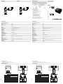
Electrical connection
Elektrischer Anschluss
Technische Daten
Technical data
Abmessungen
Dimensions
Adressen/Addresses
Sicherheitshinweise:
•Vor der Inbetriebnahme Betriebsanleitung lesen
• Anschluss, Montage und Einstellung nur durch Fachpersonal
Security Instructions:
• Read the operating instructions before attempting commissioning
• Installation, connection and adjustments should only be undertaken by specialist personnel
all dimensions in mm
www.pepperl-fuchs.com
Pepperl+Fuchs Group
68301 Mannheim · Germany
Tel. +49 621 776-4411
Fax +49 621 776-27-4411
E-mail: fa-inf[email protected]
Worldwide Headquarters
Pepperl+Fuchs Group · Mannheim · Germany
E-mail: fa-inf[email protected]
USA Headquarters
Pepperl+Fuchs Inc. · Twinsburg · USA
E-mail: fa-inf[email protected]
Asia Pacific Headquarters
Pepperl+Fuchs Pte Ltd · Singapore
E-mail: fa-inf[email protected]
Company Registration No. 199003130E
Sicherheitsgerät 1
Kanalzuordnung zu SB4 Module 4CP und 4C
Sicherheitsgerät 2
Lichtvorhang SLCT
Lichtschranken SLA12, SLA29
Empfänger Sender
OSSD 1.1 OSSD 1.2
IF-SB4-01
T
n.c.
n.c.
R
Q
PNP OSSD
Signal Sicherheitssensoren
0 V
GND
OSSD 2.1 OSSD 2.2
Klemme Kanal 1 Klemme Kanal 2 Klemme Kanal 3 Klemme Kanal 4
5 1 12 16
62 1115
7 3 10 14
84 913
Anschlussbeispiel
T-
T1
Q1
24 V DC
GND
Q2 GND
T1
R-
R1
T2
T-
T2
R2
R-
R2
R4
R3
R2
R1
13 14 15 16
1 2 3 4
5 6 7 8
9 10 11 12
R1
OSSD1
OSSD2
GND
24 V DC
DND
24 V DC
DND
R n.c. n.c.
Q0V
T
Tr = 3ms IEC 61496-1
Made in Germany Type 4
R n.c. n.c.
Q0V
T
Tr = 3ms IEC 61496-1
Made in Germany Type 4
R n.c. n.c.
Q0V
T
Tr = 3ms IEC 61496-1
Made in Germany Type 4
Sicherheitsschaltgerät Modul
Safety control unit module
IF-SB4-01
Kenndaten funktionale Sicherheit
Sicherheits-Integritätslevel (SIL) SIL 3
Performance Level (PL) PL e
Kategorie Kat. 4
MTTFd 100 a
Gebrauchsdauer (TM) 20 a
PFHd 0,62 E-9
Typ 4
Eingang
Eingangstyp PNP OSSD Signale von Sicherheitssensoren
Betätigungsspannung ON: 24 V DC + 20 %/- 30 %; OFF: < 1 V
Betätigungsstrom max. 15 mA
Ausgang
Signalausgang auf SB4 Module 4CP oder 4C
Schaltstrom min. 7,5 mA
Ansprechzeit 3 ms
Konformität
Funktionale Sicherheit ISO 13849-1
Produktnorm EN 61496-1
Umgebungsbedingungen
Umgebungstemperatur 0 ... 50 °C (32 ... 122 °F)
Lagertemperatur -20 ... 70 °C (-4 ... 158 °F)
Mechanische Daten
Schutzart IP20
Anschluss Schraubklemmen , Leitungsquerschnitt 0,2 ... 1,5 mm2
Material
Gehäuse ABS
Masse ca. 10 g
Allgemeine Informationen
Bestellinformationen Für den Anschluss werden immer zwei IF-SB4-01 benötigt
Zulassungen und Zertifikate
CE-Konformität CE
TÜV-Zulassung TÜV SÜD
NRTL-Zulassung cNRTLus
Safety unit 1
Channel assignment to SB4 Module 4CP and 4C
Safety unit 2
Light curtain SLCT
Thru-beam sensor SLA12, SLA29
Receiver Transmitter
OSSD 1.1 OSSD 1.2
IF-SB4-01
T
n.c.
n.c.
R
Q
PNP OSSD
Signal safety sensors
0 V
GND
OSSD 2.1 OSSD 2.2
Terminal channel 1 Terminal channel 2 Terminal channel 3 Terminal channel 4
5 1 12 16
62 1115
7 3 10 14
84 913
Connection example
T-
T1
Q1
24 V DC
GND
Q2 GND
T1
R-
R1
T2
T-
T2
R2
R-
R2
R4
R3
R2
R1
13 14 15 16
1 2 3 4
5 6 7 8
9 10 11 12
R1
OSSD1
OSSD2
GND
24 V DC
DND
24 V DC
DND
R n.c. n.c.
Q0V
T
Tr = 3ms IEC 61496-1
Made in Germany Type 4
R n.c. n.c.
Q0V
T
Tr = 3ms IEC 61496-1
Made in Germany Type 4
R n.c. n.c.
Q0V
T
Tr = 3ms IEC 61496-1
Made in Germany Type 4
05/25/2022
Date:
23.7
20
29.2
11.4
15.3
Functional safety related parameters
Safety Integrity Level (SIL) SIL 3
Performance level (PL) PL e
Category Cat. 4
MTTFd 100 a
Mission Time (TM) 20 a
PFHd 0.62 E-9
Type 4
Input
Input type PNP OSSD signals from photoelectric safety sensors
Actuating voltage ON: 24 V DC + 20 %/- 30 %; OFF: < 1 V
Activation current max. 15 mA
Output
Signal output on SB4 modules 4CP or 4C
Switching current min. 7.5 mA
Response time 3 ms
Conformity
Functional safety ISO 13849-1
Product standard EN 61496-1
Ambient conditions
Ambient temperature 0 ... 50 °C (32 ... 122 °F)
Storage temperature -20 ... 70 °C (-4 ... 158 °F)
Mechanical specifications
Degree of protection IP20
Connection screw terminals , Cable cross-section 0.2 ... 1.5 mm2
Material
Housing ABS
Mass approx. 10 g
General information
Ordering information For the connection are always two IF-SB4-01 is required
Approvals and certificates
CE conformity CE
TÜV approval TÜV SÜD
NRTL approval cNRTLus
23.7
20
29.2
11.4
15.3
DIN A3 -> A7
Part. 213003 45-2676F
Doc.
Type
tested
Production
monitored
Safety
tested
Production
monitored
Functional
Safety

Der Betrieb dieses Adapters ist nur an einem Sicherheits-Schaltgerät Typ SafeBox SB4 an den Modulen SB4 Module 4CP und 4C möglich.
Die Betriebsanleitung der SafeBox ist zu beachten.
Funktion
Sollen an der Safebox SB4 Lichtgitter / Lichtvorhänge mit fehlersicheren PNP-Ausgängen an einem Modul SB4 Module 4CP bzw. SB4 Module 4C
angeschlossen werden, so ist je ein IF-SB4-01 Adapter zwischen OSSD-Ausgang des angeschlossenen Sicherheitssensors und dem SB4 Module
4CP bzw. SB4 Module 4C Eingangskanal zu schalten. Die Länge der Testpulse am Ausgang des angeschlossenen Gerätes darf 200 µs nicht über-
schreiten. Die Kanäle 1 - 2 bzw. 3 - 4 des SB4 Module 4CP bzw. SB4 Module 4C müssen auf Gleichzeitigkeit überwacht werden. Die Überwachungs-
zeit beträgt 2 s.
Betriebsarteneinstellung der SB4-4CP bzw. SB4-4C Module
Auf der Baugruppe der SB4 Module 4CP bzw. SB4 Module 4C befinden sich 4 DIP-Schalter. Bei Verwendung von IF-SB4-01 Adaptern ist die Funkti-
onalität Gleichzeitigkeitsbewertung benachbarter Kanäle (1 und 2, 3 und 4) auszuwählen. Zur Funktionswahl sind stets 2 Schalter zu betätigen.
.
Lage und Bedienung der DIP-Schalter des SB4 Module 4CP bzw. SB4 Module 4C Moduls sind gemäß Datenblatt bzw. der Betriebsanleitung der Sa-
feBox zu entnehmen.
The operation of this adapter is only possible at a safety control interface unit Type SafeBox SB4 on the modules SB4, 4CP and 4C.
Please note the operating instruction for the SafeBox.
Function
If on the Safebox SB4, light grids / safety light curtains with fail-safe PNP outputs are connected to an SB4 module, modules 4CP or 4C, then in each
case an IF-SB4-01 adapter is to be connected between the OSSD output of the connected safety sensor and the SB4 Module 4CP or SB4 Module 4C
input channel. The length of the test pulse at the output of the connected device must not exceed 200 µs. Channels 1 - 2 and 3 - 4 of the SB4 Modules
4CP or SB4 Modules 4C must be monitored for simultaneity. The monitoring time is 2 s.
Operating mode setting on the SB4-4CP and SB4-4C modules
On the assembly group of the SB4 Modules 4CP and SB4 Modules 4C there are 4 DIP switches. When using IF-SB4-01 adapters the functionality of
the simultaneity evaluation of neighboring channels (1 and 2, 3 and 4) has to be selected. 2 switches always have to be actuated for the function se-
lection.
.
The position and operation of the DIP switches of the SB4 Modules 4CP and SB4 Modules 4C are given in the data sheet and the SafeBox operating
instruction.
El funcionamiento de este adaptador sólo es posible en un dispositivo de conexión de seguridad tipo SafeBox SB4 en los módulos SB4 Module 4CP
y 4C.
Deben tenerse en cuenta las instrucciones de manejo de SafeBox.
Función
Si en Safebox SB4 se conectan rejillas ópticas / cortinas ópticas con salidas PNP a prueba de fallos en un modulo SB4 Module 4CP o SB4 Module
4C, cada adaptador IF-SB4-01 debe conmutar entre la salida OSSD del sensor de seguridad conectado y el canal de entrada del SB4 Module 4CP
o SB4 Module 4C. La duración de los impulsos de prueba en la salida del dispositivo conectado no debe ser superior a 200 µs. Se debe supervisar
la simultaneidad de los canales 1 - 2 ó 3 - 4 del SB4 Module 4CP o SB4 Module 4C. El tiempo de supervisión es de 2 s.
Ajuste de tipo de funcionamiento de SB4-4CP o SB4-4C Module
En el grupo de SB4 Module 4CP o SB4 Module 4C hay 4 interruptores DIP. Si se utilizan adaptadores IF-SB4-01 debe seleccionarse la funcionalidad
de evaluación de simultaneidad de los canales contiguos (1 y 2, 3 y 4). Para seleccionar la función se deben accionar siempre 2 interruptores.
.
La posición y el manejo de los interruptores DIP de SB4 Module 4CP o SB4 Module 4C se deben consultar en la hoja de datos o las instrucciones de
manejo de Safe Box.
Il funzionamento di questo adattatore è possibile solamente con dispositivo di commutazione di sicurezza del tipo SafeBox SB4 nei moduli 4CP e 4C.
Rispettare le istruzioni per l'uso del SafeBox.
Funzione
Se al SafeBox SB4 devono essere collegate griglie optoelettriche / barriere fotoelettriche con uscite PNP a prova d'errore in un modulo SB4 4CP op-
pure SB4 4C, è necessario inserire un adattatore IF-SB4-01 tra l'uscita OSSD del sensore di sicurezza collegato e il canale di ingresso di SB4 4CP o
SB4 4C. La lunghezza degli impulsi del test all'uscita del dispositivo collegato non deve superare i 200 µs. È necessario monitorare la contemporaneità
dei canali 1 - 2 e 3 - 4 dell'SB4 4CP e/o SB4 4C. Il tempo di monitoraggio ammonta a 2 s.
Impostazione della modalità di funzionamento dei moduli SB4 4CP e SB4 4C
Sul gruppo dei moduli SB4 4CP e moduli SB4 4C si trovano 4 interruttori DIP. Utilizzando adattatori IF-SB4-01, è necessario selezionare la funzionalità
di valutazione della contemporaneità di canali adiacenti (1 e 2, 3 e 4). Per la selezione della funzione è necessario attivare sempre 2 interruttori.
.
Posizione e funzionamento degli interruttori DIP dei moduli SB4 4CP e SB4 4C possono essere ricavate dalla scheda tecnica e dalle istruzioni per l'uso
del Safe Box.
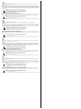
Hinweis!
Wird eine Sicherheitseinrichtung mit PNP-Ausgängen mit Hilfe des IF-SB4-01 an
SafeBox "SB4 Module 4CP" bzw. "SB4 Module 4C" angeschlossenen, so ist si-
cherzustellen, dass die Steuerleitung nach jedem Puls innerhalb von 200 µs ent-
lädt. PNP-Ausgänge, deren Ausgangstreiber als Push-Pull-Stufe aufgebaut sind,
eignen sich hierfür in besonderer Weise.
Hinweis!
Zur korrekten Gleichzeitigkeitsüberwachung der SB4 Module 4CP bzw. SB4 Mo-
dule 4C Ausgänge muss der Anschluss der PNP OSSD Ausgänge paarweise an
den Kanalpaar 1 und 2 bzw. 3 und 4 erfolgen.
Note!
If a safety device with PNP outputs is connected to SafeBox “SB4 Modules 4CP”
or “SB4 Modules 4C” using the IF-SB4-01, then care must be taken to ensure that
the control line discharges after each pulse within 200 µs. PNP outputs, whose
output drivers are constructed as a Push-Pull step, are particularly suitable for
this purpose.
Note!
For correct simultaneity monitoring of the SB4 Modules 4CP and SB4 Modules
4C outputs the connection of the PNP OSSD outputs must be made in pairs to the
channel pair 1 and 2 or 3 and 4.
¡Advertencia!
Si se conecta un dispositivo de seguridad con salidas PNP con ayuda del IF-
SB4-01 a SafeBox "SB4 Module 4CP" o bien "SB4 Module 4C", debe garantizar-
se que la línea de control descargue tras cada impulso en un intervalo de 200 µs.
Las salidas de seguridad cuyo excitador de salida esté establecido como etapa
Push-Pull son especialmente adecuadas en este caso.
¡Advertencia!
Para la correcta supervisión de simultaneidad de las salidas de SB4 Module 4CP
o SB4 Module 4C, la conexión de las salidas PNP OSSD se debe efectuar por pa-
rejas en el par de canales 1 y 2 ó 3 y 4.
Nota!
Se un dispositivo di sicurezza con uscite PNP viene collegato mediante l'IF-SB4-
01 ai "moduli SB4 4CP" o ai "moduli SB4 4C" del SafeBox, occorre assicurarsi
che la linea di controllo dopo ogni impulso si scarichi entro 200 µs. A tale scopo
sono particolarmente indicate le uscite PNP, i cui driver d'uscita sono configurati
come stadi push-pull.
Nota!
Per il corretto monitoraggio della contemporaneità delle uscite dei moduli SB4
4CP e dei moduli SB4 4C, il collegamento delle uscite PNP OSSD alle coppie ca-
nale 1-2 e 3-4 deve avvenire a coppie.
-
 1
1
-
 2
2


Pepperl+Fuchs IF-SB4-01 Istruzioni per l'uso
- Tipo
- Istruzioni per l'uso
in altre lingue
Altri documenti
-
CARLO GAVAZZI SB4315915D25 Guida d'installazione
-
Marantec EM 113 Manuale del proprietario
-
Marantec EM 111 Manuale del proprietario
-
Marantec EM 112 Manuale del proprietario
-
-
-
Marantec EM 110 Manuale del proprietario
-
Rotary SPOA3TS-5-EH1 Manuale del proprietario
-