1
2
8
1
8
8
SP1
Hyst
Sensing direction
SP1
Hyst
Sensing direction
SP1
Hyst
Sensing direction
10 V /
20 mA
10 V /
20 mA
0 V /
4 mA
0 V /
4 mA
A < B
A > B
SP1
Hyst
Sensing direction
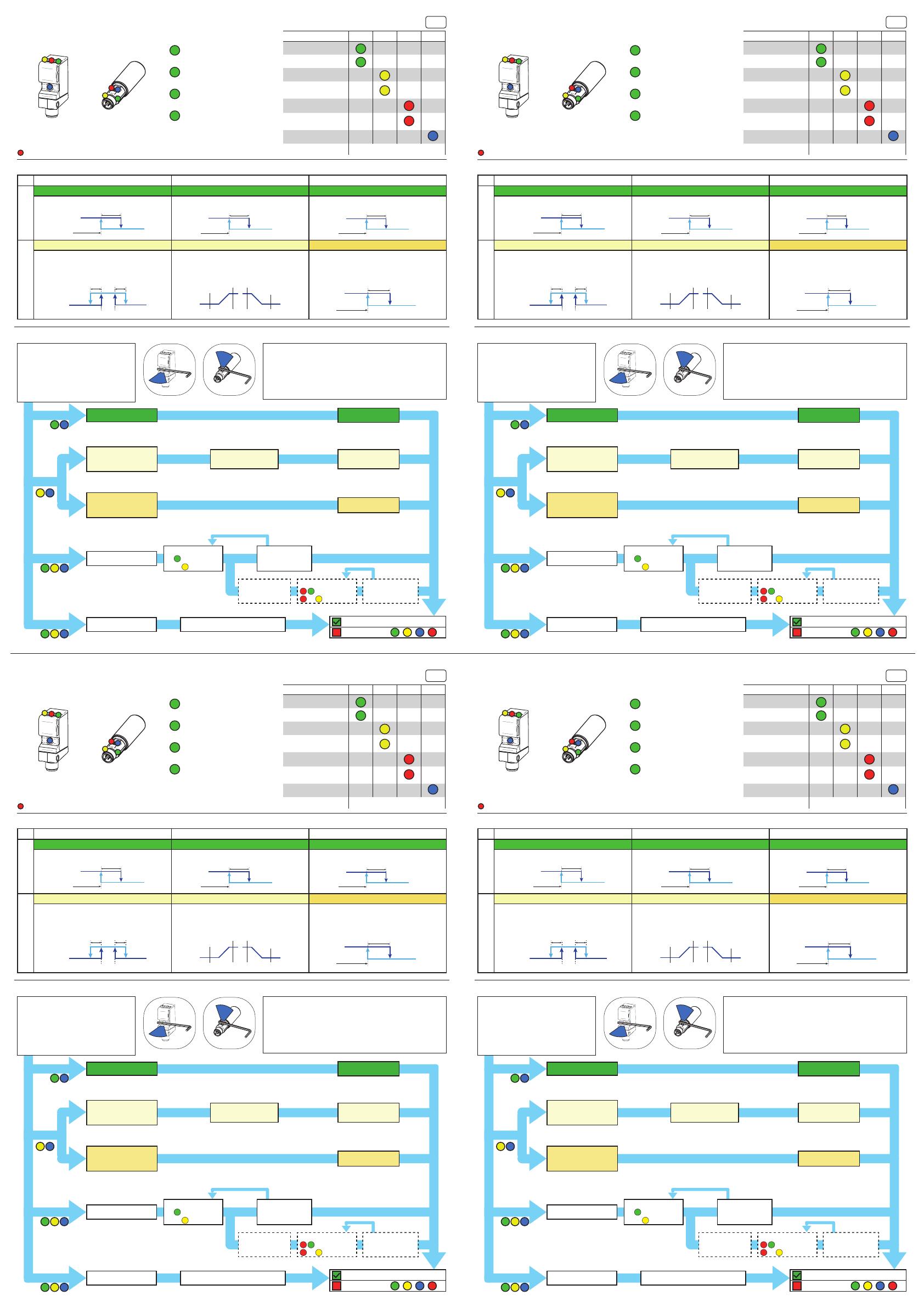
Indicateurs LED Vert Jaune Rouge Bleu
Power On
Court-circuit
Sortie 1 activée
Sortie 1 signal proche
du seuil
Sortie 2 activée
Sortie 2 signal proche
du seuil
qTeach disponible
Mode Teach-In Voir Instructions Teach-In
Indication LED Légende Mode de fonctionnement
LED ON
LED clignotante 1 Hz
LED clignotante 2 Hz
LED clignotante 8 Hz
U500.P / UR18.P avec 1 Sortie U500.D / UR18.D U500.P / UR18.P avec 2 Sortie
Niveau 1
Sortie 1: Teach 1 Point Sortie 1: Teach 1 Point Sortie 1: Teach 1 Point
Régler le point de commutation de la Sortie 1 à la
position de l’objet
Régler le point de commutation de la Sortie 1 à la
position de l’objet
Régler le point de commutation de la Sortie 1 à la
position de l’objet
Niveau 2
Teach fenêtre Teach 2 Points / Fenêtre Teach 1 Point Sortie 2
Régler une fenêtre dans laquelle un objet doit
être détecté
Régler la zone de mesure correspondante à la
sortie analogique. La Sortie 1 est active si l’objet
est dans la zone défi nie.
Régler le point de commutation de la Sortie 2 à la
position de l’objet
Description Teach-In Niveau 1 & 2
Seuls les détecteurs avec 2 sorties ont une LED rouge
FR
Teach-in OK
Teach-in NOK
2 sec / Level 1
4 sec / Level 2
6 sec / Level 3
8 sec / Level 4
8
8
8 8
X
1 11
2 22
2 2
2 2
Teach 1 Point Placer l’objet & TAP
Teach 2 Points /
Fenêtre
(Uxxx.P / Uxxx.D)
Placer l’objet à la
position A & TAP
Placer l’objet à la
position B & TAP
Teach 1 Point
Sortie 2
(Uxxx.P avec 2 sorties)
Placer l’objet & TAP
Logique de
commutation
TAP pour changer
le réglage
Option: Maintenir
2 sec pour pas-
ser à la Sortie 2
Remise confi guration
usine
Attendre pour la confi guration usine
Instructions Teach-In
TAP pour changer
le réglage
Indication Logique
NO, Sortie 1
NC, Sortie 1
Indication Logique
NO, Sortie 2
NC, Sortie 2
1
2
8
1
8
8
SP1
Hyst
Sensing direction
SP1
Hyst
Sensing direction
SP1
Hyst
Sensing direction
10 V /
20 mA
10 V /
20 mA
0 V /
4 mA
0 V /
4 mA
A < B
A > B
SP1
Hyst
ection
Indicazioni LED Verde Giallo Rosso Blu
Power On
Corto circuito
Uscita 1 attiva
Uscita 1 prossima alla
soglia
Uscita 2 attiva
Uscita 2 prossima alla
soglia
qTeach utilizzabile
Modalità di Teach-In see Teach-In Instruction
Indicazioni LED Legenda Modalità operativa
LED on
Lampeggiamento LED a 1 Hz
Lampeggiamento LED a 2 Hz
Lampeggiamento LED a 8 Hz
U500.P / UR18.P con 1 uscita U500.D / UR18.D U500.P / UR18.P con 2 uscite
Livello 1
Uscita digitale – teach ad 1 punto Uscita digitale – teach ad 1 punto Impostazione uscita 1
Impostare il punto di commutazione dell’uscita 1
alla posizione desiderata
Impostare il punto di commutazione dell’uscita
digitale alla posizione desiderata
Impostare il punto di commutazione dell’uscita 1
alla posizione desiderata
Livello 2
Soglia di commutazione a fi nestra Teach del range di misura a 2 punti Impostazione uscita 2
Impostare una soglia di commutazione a fi nestra
all’interno della quale rilevare l’oggetto
Impostare il range di misura relativo all’uscita
analogica. Se l’uscita digitale non viene impostata
nel livello 1 rimane sempre attiva all’interno del
range di misura.
Impostare il punto di commutazione dell’uscita 2
alla posizione desiderata
Descrizione livelli di Teach-in 1 e 2
Solo i sensori con 2 uscite hanno un LED rosso
IT
Teach-in OK
Teach-in NOK
2 sec / Level 1
4 sec / Level 2
6 sec / Level 3
8 sec / Level 4
8
8
8 8
X
1 11
2 22
2 2
2 2
Campo di misura /
Finestra
(Uxxx.P / Uxxx.D)
Posizionare oggetto a
Posizione A & TAP
Posizionare oggetto a
Posizione B & TAP
Teach-in ad punto 1 per
uscita 2
(Uxxx.P a 2 uscite)
Posizionare oggetto
& TAP
Uscite logiche
TAP modifi care
l’uscita
Opzionale:
Toccare 2 sec. In
piu per modifi care
l’uscita 2
TAP modifi care
l’uscita
Factory Reset
Non toccare il punto di teach-in
Logica di indicazione
NO, fuori 1
NC, fuori 1
Logica di indicazione
NO, fuori 2
NC, fuori 2
Teach-in OK
Teach-in NOK
2 sec / Level 1
4 sec / Level 2
6 sec / Level 3
8 sec / Level 4
8
8
8 8
X
1 11
2 22
2 2
2 2
1-point teach
Colocar Objeto & Tap
2 point teach/
Ventana
(Uxxx.P / Uxxx.D)
Colocar Objeto en
Posición A & Tap
Colocar Objeto en
Posición B & Tap
1 point teach
Salida 2
(Uxxx.P con 2 salidas)
Colocar Objeto & Tap
Lógica de salida
TAP para cambiar
Opcional: Mantener
2 seg para cambiar a
Salida 2
TAP para cambiar
Reset a valores fábrica
Esperar a que se realice el Reset
Instrucciones Teach-In
Indicación lógica
NO, salida 1
NC, salida 1
Indicación lógica
NO, salida 2
NC, salida 2
1
2
8
1
8
8
SP1
Hyst
Sensing direction
SP1
Hyst
Sensing direction
SP1
Hyst
Sensing direction
10 V /
20 mA
10 V /
20 mA
0 V /
4 mA
0 V /
4 mA
A < B
A > B
SP1
Hyst
Sensing direction
LED Indicators green
yellow
red blue
Power On
Cortocircuito
Salida 1 activa
Salida 1 señal dentro
del intervalo
Salida 2 activa
Salida 2 señal dentro
del intervalo
qTeach disponible
Modo Teach-In Ver instrucciones Teach-In
Información LED Leyenda Operating Mode
LED ON
LED parpadeo 1 Hz
LED parpadeo 2 Hz
LED parpadeo 8 Hz
U500.P / UR18.P con 1 salida U500.D / UR18.D U500.P / UR18.P con 2 salida
Nivel 1
1 punto de enseñanza de salida 1 1 punto de enseñanza de salida 1 1 punto de enseñanza de salida 1
Defi nir el punto de conmutación de la salida 1 en
la posición del objeto
Defi nir el punto de conmutación de la salida 1 en
la posición del objeto
Defi nir el punto de conmutación de la salida 1 en
la posición del objeto
Nivel 2
Aprendizaje de ventana 2-Point Teach/Ventana 1-Point Teach Salida 2
Defi nir una ventana de detección del objeto Defi nir el intervalo de medición respecto a la
salida analógica. La salida 1 se activa si detecta
un objeto dentro del intervalo.
Defi nir el punto de conmutación de la salida 2 en
la posición del objeto
Descripción Teach-In Nivel 1 & 2
Sólo los sensores con 2 salidas disponen de un LED rojo
ES
1
2
8
1
8
8
SP1
Hyst
Sensing direction
SP1
Hyst
Sensing direction
SP1
Hyst
Sensing direction
10 V /
20 mA
10 V /
20 mA
0 V /
4 mA
0 V /
4 mA
A < B
A > B
SP1
Hyst
ection
LED 指示灯 绿 黄 红 蓝
通电
短路
输出 1 激活
输出 1 信号接近阈值
输出 2 激活
输出 2 信号接近阈值
qTeach 可使用
Teach-in 模式 详见 Teach-in 说明
LED 指示灯 图例 操作模式
LED 亮
LED 闪烁 1 Hz
LED 闪烁 2 Hz
LED 闪烁 8 Hz
U500.P / UR18.P 单输出
U500.D / UR18.D
U500.P / UR18.P 双输出
1级
1 点设定 输出 1 1 点设定 输出 1 1 点设定 输出 1
将输出 1 的开关点设置在被测物的位置 将输出 1 的开关点设置在被测物的位置 将输出 1 的开关点设置在被测物的位置
2级
窗口设定 2 点设定/窗口设定 1 点设定 输出 2
设置一个被测物应被检测到的窗口 设置与模拟值相对应的测量范围. 如果被测物处于
测量范围内, 则输出 1 处于激活状态
将输出 2 的开关点设置在被测物的位置
Teach-In 说明 1 级 & 2 级
仅带2路输出的传感器有红色LED
CN
Teach-in OK
Teach-in NOK
2 sec / Level 1
4 sec / Level 2
6 sec / Level 3
8 sec / Level 4
8
8
8 8
X
1 11
2 22
2 2
2 2
1 点设定 放置被测物并触碰
2 点设定 /
窗口设定
(Uxxx.P / Uxxx.D)
将被测物放置于位置
A 并触碰
将被测物放置于位置
B 并触碰
1 点设定 输出 2
(Uxxx.P 有2个输出)
放置被测物并触碰
输出逻辑
触碰来改变设定
可选: 保持 2 秒改
变至输出 2
触碰来改变设定
恢复出厂设置 期间不进行任何设定
设定说明
指标逻辑
NO, 出 1
NC, 出 1
指标逻辑
NO, 出 2
NC, 出 2
Entrée en mode Teach:
- Placer l‘outil ferromagnétique comme indiqué
ci-contre de activer qTeach® ou
connecter le fi l Teach-In au +Vs.
- Si le Teach est activé correctement, les LED
jaune et verte sont allumées.
- Enlever après n sec pour le niveau souhaité.
Un TAP est une courte touche (>100 ms) de l‘outil
comme présenté ci-contre.
Information Générale
- qTeach® se verrouille 5 min après la mise tension.*
- S‘il est verrouillé, qTeach® peut être réactivé en réappliquant la puissance ou
en connectant le fi l de Teach-In pendant >15 sec. à +Vs
- Le Teach externe est toujours disponible (Pas de verrouillage)
- En mode Teach la sortie est à 0V
- En mode normal l‘entrée Teach est à 0V
- Pour un Teach externe, connecteur l‘entrée Teach correspondant au +Vs
Informazione generali
- La funzione di qTeach ® si disattiva dopo 5min dall‘accensione del sensore.*
- Se disablitato, qTeach® può essere riattivato mediante riapplicazione della potenza o
collegando il fi lo Teach-In per >15 sec. a +Vs
- In modalità Teach-In l‘output assume un valore pari a 0V.
- Il Teach-In da remoto è sempre possibile (non si disattiva dopo 5 min).
- Durante il normale funzionamento del sensore il cavo Teach-In va messo a 0V.
- Per il Teach-In da remoto, connettere il cavo di teach a +Vs.
Selezionare il livello di Teach-In
- Posizionare l‘utensile ferromagnetico come
mostrato a destra di attivare qTeach® o collegare
il cavo Teach-In a +Vs.
- Se l‘utensile viene riconosciuto correttamente,
entrambi i LED si accendono.
- Rimuovere dopo n sec. per il livello desiderato.
Un TAP è un breve tocco (>100 ms) dell‘utensile come
mostrato a destra.
Istruzioni Teach-In
Entrar en modo Teach:
- Coloque la herramienta ferromagnética como
indica la imagen para activar qTeach® o
conectar el cable Teach-In a +Vs.
- LEDs verde y amarillo encendidos si la herramien-
ta o el teach-in se reconocen correctamente.
- Retirar tras n segundos para el nivel deseado.
Un TAP es un toque corto (>100 ms) de la
herramienta.
Información general
- qTeach® se bloquea 5 min después de la alimentación.*
- Si está bloqueado, qTeach® puede ser reactivado mediante la aplicación de
energía o conectando el cable de Teach-In para >15 seg. a +Vs
- El teach-in externo está siempre disponible (no se bloquea).
- En modo teach la salida cambia a 0V.
- En modo normal el cable deteach se pone a 0V.
- Para teach-in externo, conectar el cable teach a +Vs.
进入设定等级:
- 如右图所示放置金属工具或连接设定线至
+Vs
-如果工具或设定被恰当地识别到, 绿色和黄
色LED将亮起.
- 在 n 秒后档选定所需的等级 是拿开
触碰是如右图所示用工具快速靠近感应区域
总览:
- qTeach 开启5分钟后自行锁定, 蓝色LED 熄灭.
- 在设定模式下输出变至 0 V.
- 在通常情况西设定先接至 0 V.
- 对于外部设定, 将设定线连接至 +Vs.
- 外部设定线永久有效 (无自锁)
- 放置工具 > 12 秒.:在等级设定过程中而不做任何更改.
Posizionare oggetto
& TAP
Teach-in ad punto 1

