La pagina si sta caricando...

• Applicare il frontalino.
• Eseguire il Walk Test verificando le
rilevazioni tramite i led.
• Serrare la vite di chiusura.
• Applicare il filtro led coprivite.
Questo elemento ha una duplice
funzione:
- permette di lasciare i led accesi
in modo che non possano
essere visti a distanza da un eventuale
intruso, permettendo di verificare nelle
sue immediate vicinanze il
funzionamento del sensore da parte
dell’utente;
- maschera esteticamente la vite di
chiusura del sensore.
DESCRIZIONE DEL PRODOTTO
Sensore Doppia Tecnologia (MW + IRP) volumetrico a Tenda per
esterno
Caratteristiche tecniche
• Sistema globale di autopro-tezione, escludibile e parzializzabile,
composto da un antimascheramento della microonda più un
antimascheramento attivo della lente dell’infrarosso.
• 4 settaggi di sensibilità ottimizzati per interno, esterno,
avvicinamento, attraversamento, in abbinamento al trimmer per
la regolazione globale della portata
• Barriera 12 mt x 200cm.
• Contenitore in policarbonato IP65 resistente agli agenti atmosferici
• Compensazione della temperatura ambientale
• Filtro ottico selettivo della banda Infrarossa
• Memoria di allarme, memoria di mascheramento e gestione
interattiva dello spegnimento dei led.
• Possibilità di istallazione parete / parete o soffitto / pavimento
con l’ausilio della staffa angolare in dotazione e dello snodo
HUB opzionale.
• Ottica a fessura profonda per una alta immunità della sezione
Infrarosso a tutti i fenomeni/disturbi che non si presentino nel
suo effettivo campo visivo di rilevazione.
INSTALLAZIONE
1 - Aprire il sensore svitando la vite di chiusura.
2 - Smontare l’insieme fondo intermedio e scheda elettronica dal
fondo .
A muro o con staffa angolare
3 - Incidere la sede A e la sede B nel fondo
4 - Far passare il cavo attraverso l’apertura cavo del fondo.
5 - Per installazione diretta a muro fissare il fondo con le apposite
viti tramite le sedi A e B.
6 - Per installazione con staffa angolare*, fissare prima la staffa
alla parete con le apposite viti e poi fissare il fondo alla staffa
tramite le sedi A e B con le viti di fissaggio a staffa.
7 - Passare il cavo attraverso il gommino sul fondo intermedio,e
reinserire l‘insieme fondo intermedio e scheda elettronica sul
fondo già fissato.
8 - Procedere con il collegamento dei cavi
*La staffa angolare può essere indifferentemente montata con verso
destro o sinistro.
Con snodo AF969S ( opzionale )
Lo snodo HUB-P sarà applicato in maniera orizzontale o direttamente al
muro con le apposite viti e tasselli, o sul supporto HUB-CP tramite le viti
di fissaggio staffa.
Permetterà orientamenti di +/- 45° sul piano verticale, e +30°, nel verso
contrario a quello delle “Frecce di orientamento”, sul piano orizzontale.
3 - Far passare il cavo di collegamento attraverso lo HUB-P e
l’apertura cavo.
4 - Serrare il fondo sullo snodo con le viti di fissaggio staffa
attraverso le sedi C e D.
5 - Orientare lo snodo e serrare la vite di bloccaggio snodo attraverso
l’apertura cavo.
6 - Passare il cavo attraverso il gommino sul fondo intermedio
e reinserire l‘insieme fondo intermedio e scheda elettronica
sul fondo già fissato.
7 - Procedere con il collegamento dei cavi.
Collegamento dei cavi
• Collegare il cavo alla morsettiera secondo lo schema.
• Regolare la portata tramite il trimmer (vedi capitolo settaggi)
• Eseguire se necessario il settaggio di funzionamento (vedi
capitolo settaggi)
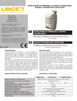
AF969F Rivelatore ad effetto
tenda da esterno
Vite di chiusura
Vite scheda
Fondo
Filtro Led
coprivite
Ottica
Infrarosso
Scheda
elettronica
Gommino
Fondo intermedio
Sede D
Sede C
Centratori
Frecce di
orientamento
HUB CP
HUB P
Vite per fissaggio
staffa
Sede B
Sede A
Vite per fissaggio
staffa
Viti per
fissaggio
a muro
Apertura
cavo
Fondo
Staffa
angolare
International Trademark registration n° 327040 - 942905 - 330600

Morsettiera
CONSIGLI PER L’INSTALLAZIONE
In installazioni da interno preferire posizionamenti del sensore
verso l’interno del locale e lontano da macchinari in movimento e
fonti di calore. Evitare di dirigerlo verso vetrate esposte al sole. In
installazioni da esterno, evitare che i raggi del SOLE specialmente
nelle ore più calde della giornata, arrivino diretti all’elemento sen-
sibile dell’Infrarosso.
Nota: prestare attenzione a non oscurare, neanche
parzialmente, il campo di visione del rilevatore.
PET IMMUNITY
Qualora vi sia la possibilità di transito di piccoli animali domesti-
ci nella zona protetta utilizzare il parzializzatore di lente fornito,
applicandolo* sulla lente in modo da lasciar scoperte solo le due
zone superiori.
Il risultato ottenuto è quello della figura sotto.
Applicazione del Parzializzatore Lente
Smontare il Portalente svitando le viti A e B.
Estrarre la lente ed applicare l’adesivo lasciando scoperte solo le
due Zone più alte.
Rimontare il la Lente ed il Portalente eseguendo la procedura
inversa.
*Nota: la portata del sensore è stabilita dal trimmer in funzione
della massa di un corpo umano. Animali di grande taglia (cavalli,
mucche ) od oggetti in movimento di grossa massa ( autoveicoli )
possono essere rilevati a distanze maggiori.
Ove non sia possibile una installazione Parete/Parete o Soffitto/
Pavimento prediligere l’installazione a sensore inclinato.
Escludere dalla zona di rilevazione del sensore qualsiasi oggetto in
movimento od oscillante.
Per protezioni di pareti, evitare che una zona sensibile dell’Infra-
rosso trovi a contatto con il muro per non annullare il beneficio del
sensore infrarosso a doppio elemento.
Ovviare a questo montando il sensore distaccato dal muro (vedi
tabella),
od orientando il sensore di qualche grado ( < 10°) utilizzando
l’accessorio optional Snodo AF969S.
Prediligere installazioni ove ci sia un muro / pavimento a deli-
mitare il campo di rilevazione del sensore. Non puntare quindi il
sensore nel vuoto
–
INPUT: ingresso riconoscimento
impianto inserito / disinserito.
Ingresso alimentazione (12V cc)
Contatto tamper normalmente
chiuso
Rele allarme normalmente chiuso
Rele antimask normalmente
chiuso
12V TAMP ALL MASK
+ – NC NC NC

SETTAGGI
Attraverso il posizionamento dei 5 Dip Switch è possibile adattare
il funzionamento del sensore alla propria esigenza installativa.
ANTIMASK GLOBALE
- Antimascheramento
totale MW + IR
<Non certificato
perché non previ-
sto nel Grado 2 >
DipSwitch N°1 in
pos. ON e frontalino
chiuso
Qualsiasi elemento in
grado di mascherare
la MW o la lente del
PIR genera un allarme
visualizzato tramite il
lampeggio dei tre LED,
ed inviato in centrale
tramite il collegamento
al morsetto MASK. Tale segnalazione permane fintanto che non
viene rimossa la causa che l’ha generata.
L’ abilitazione della funzione ANTIMASK sarà attiva solo dopo aver
chiuso il frontalino e porterà il sensore in condizione di MaskAdjust
In questa condizione, in cui i Led lampeggeranno alternativamente
per circa 60 sec, il sensore calibrerà i suoi livelli di Antimask.
Chiuso il frontalino è quindi necessario togliere le mani dal sen-
sore e non mettere e non muovere nulla nelle sue immediate
vicinanze.
Al termine del MaskAdjust il sensore sarà pronto al funzionamen-
to.
Si dispongono automaticamente due livelli di sensibilità dell’ An-
timascheramento selezionando il funzionamento Esterno /Interno:
• In INTERNO sensibilità massima
* Nota: a seconda delle necessità, è possibile effettuare una
parzializzazione diversa delle zone di rilevazione dell’Infrarosso
tagliando opportunamente l’adesivo e lasciando scoperte altre
zone della lente.
• In ESTERNO sensibilità ottimizzata su perturbazioni atmosferiche
ESCLUSIONE ANTIMASK MW - DipSwitch N°4 in pos. ON
Si può escludere l’antimascheramento di Microonda per istalla-
zioni che presentino corpi solidi in movimento nelle immediate
vicinanze del sensore e che potrebbero generare allarmi di ma-
scheramento: Tapparelle di metallo; Persiane di metallo etc.
INTERNO / ESTERNO - Dip Switch n° 2 in pos. OFF Esterno / in
pos. ON Interno
Si ha la possibilità di selezionare l’algoritmo più idoneo, come sen-
sibilità e velocità, al tipo di installazione scelta al fine di abbattere
i falsi allarmi ed avere comunque sempre la massima capacità di
rilevazione possibile nella condizione scelta.
• In INTERNO si ha una capacità di rilevazione e di reiezione ai
falsi allarmi tipica dei sensori volumetrici da interno.
• In ESTERNO la capacità di rilevazione è stata ottimizzata con-
siderando i possibili disturbi provocati da perturbazioni atmosferi-
che.
Nota: è possibile invertire l’uso dei due settaggi ( ESTERNO all’
interno di un edificio, ed INTERNO per uso all’esterno ) qualora
l’installatore identifichi un sito esterno con bassa possibilità di
interferenza, o un sito interno con alta possibilità di falso allarme.
ATTRAVERSAMENTO / AVVICINAMENTO - Dip Switch n° 3 in
pos OFF Attraversamento / in pos ON Avvicinamento
In una protezione a barriera è necessario stabilire nel momento
dell’istallazione, quale sarà la direzione di transito dell’intruso in
funzione della barriera stessa.
I due settaggi sono quindi ottimizzati a sfruttare al meglio le di-
verse caratteristiche di rilevazione dei due Sensori (microonda
e Piroelettrico ) in queste due diverse situazioni di rilevazione.
Considerazioni sulle Sensibilità settabili:
Tramite i dip switch n°2 e n°3 si hanno a disposizione 4 diverse
sensibilità di rilevazione che sono state ottimizzate per il funzio-
namento in installazioni per esterno o per interno, con movimenti
in avvicinamento al sensore o per l’ attraversamento del suo lobo
di rilevazione.
Il livelli di sensibilità, ordinati per velocità di rilevazione ( dal più
veloce 1° al più lento 4° ), sono elencati nella tabella seguente:
1° Interno Attraversamento
2° Interno Avvicinamento
3° Esterno Attraversamento
4° Esterno Avvicinamento
LED OFF
DipSwitch N°5 in pos. ON
Disattiva le visualizzazioni di rilevazione, mantenendo abilitate le
visualizzazioni relative alle memorie.
TRIMMER
Regola la portata del sensore.
Per la regolazione tenere a riferimento il campo di azione deter-
minato dalla microonda. Il sensore adeguerà automaticamente il
funzionamento dell’ infrarosso a questa regolazione.
Nota: al contrario della microonda, per la quale è possibile sta-
bilire con sufficiente precisione il suo limite di rilevazione, per
l’infrarosso questa condizione non è applicabile.
Questo perché la rilevazione dell’infrarosso è condizionata dalla
temperatura ambientale, dall’abbigliamento dell’intruso,dalla
assenza/presenza di vento etc.
Il trimmer quindi regola automaticamente la capacità di rileva-
zione dell’Infrarosso in funzione della portata della microonda
selezionata senza necessariamente delimitarne il suo campo
di azione a quello della microonda stessa ( l’ infrarosso sarà
configurato per le condizioni più sfavorevoli a quella portata ).
Si potranno avere quindi rilevazioni di infrarosso anche a distan-
za maggiore di quella stabilita dal trimmer senza che questo
comprometta l’affidabilità del sensore
DIP SWITCH
1 MASK GLOGALE IR + MW
ON = INSERITO
OFF = DISINSERITO
2 ESTERNO / INTENO
ON = INTERNO
OFF = ESTERNO
3
ATTRAVERSAMENTO
AVVICINAMENTO
ON = AVVICINAMENTO
OFF = ATTRAVERSAMENTO
4 ESCLUSIONE MASK MW
ON = MASK MW ESCLUSO
OFF= MASK MW NON ESCLUSO
5 LED OFF
ON = LED SPENTI
OFF = LED ACCESI
Tab.1
VISUALIZZAZIONI
Led BLU Led ROSSO Led GIALLO
MW ALLARME IR
ANTIMASK LAMP LAMP LAMP

FUNZIONI CON LINEA INPUT
Questo set di funzioni vengono attivate / disattivate tramite l’inse-
rimento / disinserimento dell’impianto.
A tale proposito viene considerato:
• 12V sull’ ingresso INPUT = impianto disinserito
• 0V sull’ ingresso INPUT = impianto inserito
ABILITAZIONE REMOTA LED CONDIZIONE RICHIESTA LED
OFF
( Dip Switch 5 in pos. ON )
Al disinserimento dell’impianto, il sensore si predispone alla riabi-
litazione delle visualizzazioni di rilevazione.
Le visualizzazioni verranno riabilitate alla prima rilevazione effet-
tuata, e rimarranno attive per 30sec.
MEMORIE
Al disinserimento dell’impianto,verrà visualizzata la memoria del
primo allarme avvenuto, come in tab.2.
La memoria verrà resettata al successivo inserimento dell’impianto.
RITARDO della MEMORIA per utilizzo in ZONE TEMPORIZ-
ZATE
Tempo di uscita: gli allarmi che si verificano entro i primi 30” dall’
inserimento dell’impianto vengono cancellati.
Tempo di ingresso: gli allarmi che si verificano 30” prima del di-
sinserimento dell’impianto vengono cancellati.
SPECIFICHE TECNICHE
Alimentazione: 12V +/- 3V
Assorbimento Max (in memoria di all.): 32mA
Assorb. Stand By: 20mA
Microonda: 24 Ghz
Tempo Allarme: 3 sec
Opto Rele’ : 100mA / 24V
Tamper: 100mA /30V
Wall Tamper: 300mA / 48V
Temperatura lavoro: -10°C/+55°C
Umidità Ambientale: 95%
MTBF Teorico: 120.000 ORE
Dimensioni senza accessori 110 x44 x 46mm
Livello Prestazione: EN50131-2-4
Grado 2, CLASSE IV
Tab.2
VISUALIZZAZIONI IN STATO DI MEMORIA
Led BLU Led ROSSO Led GIALLO
PIR+MW SPENTO ACCESO SPENTO
ANTIMASK LAMP ACCESO LAMP
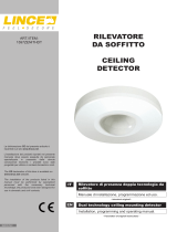
PRODUCT DESCRIPTION
Dual technology detector (MW + IRP) volumetric curtain effect for
outdoor applications.
TECHNICAL FEATURES:
• Global self-protection, excludable and partialized, composed of
an antimask on the microwave and an antimask on the IR lens
by active infrared.
• 4 sensitivity settings optimized for Inside, Outside, Approach,
Crossing, in combination with the trimmer for the adjustment of
the coverage
• Barrier 12 mt x 200cm.
• Polycarbonate case IP65, resistant to environmental agents
• Environment temperature compensation
• Selective Optical Filter of the Infrareds bandwidth
• Alarm memory, Antimask memory, and interactive management
of Led OFF.
• Ability to wall / wall installation or ceiling / floor installation using
the supplied angle bracket and the optional pivot bracket Hub
• Deep optical slot for a high immunity of the infrared section to
all of the phenomena / disorders that do not show up in its field
of detection view .
• Filter LED,to enable the vision of the detection only close of the
detector
INSTALLATION
1 - Open the detector by unscrewing the closing screw.
2 - Remove all, intermediate plastic bottom and circuit board,
from the plastic bottom.
To the wall or with angle bracket
3 - Cut the locations A and B on the plastic bottom
4 - Pass the cable through the cable entry on the plastic bottom
5 - For direct mounting to the wall, fix the plastic bottom with the
screws through the locations A and B.
6 - For installation with angle bracket *, attach first the bracket to
the wall with the screws and then attach the plastic bottom
to the bracket through locations A and B with the angle bracket
screws.
7 - Pass the cable through the rubber on the intermediate plastic
bottom and replace the all, intermediate plastic bottom and
circuit board, on the plastic bottom.
8 - Proceed with the cable connection.
*The Angle Bracket can be mounted either left or right handed.
With Swivel Bracket AF969S (optional)
The Swivel Bracket HUB-P will be applied in a horizontal manner, or directly
to the wall with screws and dowels, or on the support HUB-CP through the
Angle Bracket screws.
The HUB-P allows orientation of + / - 45 ° vertically, and +30 ° in the
opposite direction to that of the “Guidance Arrows”, in the horizontal plane.
3 - Pass the cable through the swivel bracket and the cable entry
4 - Place the plastic bottom on the swivel bracket with the angle
brachet screws through the location C and D.
5 - Orient the swivel bracket and tighten the locking screw
through the cable entry.
6 - Pass the cable through the rubber on the Intermediate plastic
bottom and replace the all, intermediate plastic bottom and
circuit board, on the plastic bottom
7 - Proceed with the cable connection.
Cable connection
• Connect the cable to the terminal as in the scheme.
• Adjust the range through the trimmer (see chapter settings)
• If it is necessary, perform the setting of operating. (see chapter
settings)
• Apply the plastic front.
• Run the walk test by checking the detections through the
LEDs.
• Tighten the closing screw.
• Apply the filter LED. This element has a dual function:
- allows you to leave ON the LEDs so that they can not be seen
AF969F Outdoor curtain effect
detector
DICHIARAZIONE DI CONFORMITA’
Ave spa dichiara che questa apparecchiatura è compatibile con gli
essenziali requisiti previsti dalla Direttiva 1999/5/EC

at a distance by an intruder, but allowing the verification of
operation only in the immediate vicinity of the sensor by the
user;
- hide aesthetically the closing screw of the detector
Closing screw
Card screw
Plastic
Bottom
Filter Led
Infrared
Optics
Circuit
Board
Rubber Intermediate Plastic
Bottom
Location D
Location C
Centering
Guidance
Arrows
HUB CP
HUB P
Angle Bracket’s
Screw
Location B
Location A
Angle Bracket’s
Screw
Screws
for wall
mounting
Cable
entry
Plastic
Bottom
Angle
Bracket
TERMINAL
–
INHIBIT: input signal to detect if the
system is armed or not armed.
Power supply input (12V dc)
Normally closed tamper contact
Normally closed alarm output
Closed contact antimask
output, normally.
12V TAMP ALL MASK
+ – NC NC NC
TIPS FOR INSTALLATION
In indoor installations, prefer placement of the sensor toward the
inside of the room and away from operating machinery and heat
sources. Avoid to direct it toward the windows exposed to the
sunny. In outdoor installations, prevent that the sun’s rays, es-
pecially during the hottest hours of the day, come directly to the
infrared sensing element.
For protection of walls, avoid that a sensitive area of infrared is in
contact with the wall, in order to don’t cancel the benefit of the
dual-element infrared sensor.
Overcome this by mounting the sensor detached from the wall
(see table),
or orienting the sensor of a few degrees (<10 °) using the optional
accessory Swivel Bracket Hub P + HUB-CP.
To prefer installations where there is a wall / floor to delimit the
field of detection of the sensor. Do not point the sensor in a vac-
uum space.

PET IMMUNITY
If there is the possibility of transit of pets in the protected zone,
use the Blinding’s lens provided by applying it* on the lens so as
to leave uncovered only the two upper zones.
The result is it in the figure below.
TIPS FOR INSTALLATION
In indoor installations, prefer placement of the sensor toward the
inside of the room and away from operating machinery and heat
sources. Avoid to direct it toward the windows exposed to the
sunny. In outdoor installations, prevent that the sun’s rays, es-
pecially during the hottest hours of the day, come directly to the
infrared sensing element.
Aplication of Blinding’s lens
Remove the lens blocker by unscrewing the screws A and B.
Remove the lens and apply the adhesive “Blinding’s lens” leaving
uncovered only the two highest zones.
Refit the lens and the lens blocker by doing the reverse procedure.
SETTING
Through the positioning of the 5 Dip Switches is possible to adapt
the sensor working to the your installing needs.
* Note: Depending on your needs, you can make a different
partitioning of the areas of the infrared detection by cutting
appropriately the Blinding’s lens and leaving uncovered other
zones of the the lens
DIP SWITCH
1 GLOBAL MASK IR + MW
ON = ACTIVED
OFF = DEACTIVATED
2 OUTDOOR / INDOOR
ON = INDOOR
OFF = OUTDOOR
3 CROSSING / APPROACH
ON = APPROACH
OFF = CROSSING
4
MW ANTIMASK
DEACTIVATION
ON = DEACTIVED
OFF= ACTIVATED
5 LED OFF
ON = LED OFF
OFF = LED ON
GLOBAL ANTIMASK
- Total Antimask MW + IR
DipSwitch N°1 in pos. ON
and Plastic Front closed
Any element that can mask
the MW or the lens of the
IR generates an alarm dis-
played by the three flashing
LEDs, and sent to the cen-
tral through the connection
terminal MASK.
This signal remains until it
is removed the cause that
generated it.
The enabling of Antimask
function will be active only
after the closing of the plas-
tic front and will bring the sensor in a condition to MaskAdjust. In
this condition, in which the LEDs will flash alternately for about 60
seconds, the sensor will calibrate its antimask levels.
Closed the Plastic Front is therefore necessary to remove your
hands from the sensor, and do not move and do not put anything
in its immediate vicinity.
At the end of MaskAdjust the sensor will be ready for operation.
You automatically have two levels of sensitivity of the AntiMask
selecting the operation OUTDOOR/INDOOR:
INDOOR : maximum of sensitivity
OUTDOOR: optimized sensitivity on atmospheric disturbances
EXCLUSION of MW’s ANTIMASK - DipSwitch N°4 in pos. ON
You may exclude the Antimask of Microwave in installations that
presenting solid bodies in motion in the immediate vicinity of the
sensor and which could cause Antimask alarms : Blinds of metal,
shutters of metal, etc.
INDOOR /OUTDOOR - Dip Switch n° 2 in pos OFF Outdoor / in pos
ON Indoor
You have the ability to select the most suitable algorithm, such as
sensitivity and speed, to the type of installation chosen in order
to reduce false alarms and to have always the highest detection
capability in the installation you have choose.
INDOOR has a capacity of detection and false alarm rejection
typical of indoor volumetric sensors.
In OUTDOOR, the detection capability has been optimized
considering the possible disturbances caused by atmospheric

disturbances.
Note: the Installer can reverse the use of two settings (OUTDOOR to the
Indoor of a building, and INDOOR for outdoor use) if the Installer detects
an external site where there is a low possibility of interference, or an
internal site where there is high possibility of false alarm.
CROSSING / APPROACH
- Dip Switch n° 3 in pos OFF Crossing
/ in pos ON Approach
In a Barrier protection is necessary to establish at the time of
installation, which will be the transit direction of the intruder in
reference of the barrier. The two settings are then optimized to
exploit the different characteristics of the two detection sensors
(MW and IR) in these two different situations of detection.
Considerations about the selectable sensitivities :
Using the dip switch No. 2 and No. 3 will have 4 different sensitiv-
ity of detection that have been optimized for operation in installa-
tions for outdoor or indoor, with movements that approaching the
sensor, or crossing its detection lobe .
The levels of sensitivity, sorted by sensing speed (from fastest 1 ^
to slowest ^ 4), are listed in the table below:
1^ Indoor Crossing
2^ Indoor Approach
3^ Outdoor Crossing
4^ Outdoor Approach
LED OFF DipSwitch N°5 in pos. ON
Disable the views of detection, keeping enabled the views of the
memories.
Tab.1
DISPLAY
Led BLU Led ROSSO Led GIALLO
MW ALARM IR
ANTIMASK FLASH FLASH FLASH
TRIMMER
Adjusts the range of the sensor.
To the adjusting to keep as a reference the range determined
by the microwave (MW). The sensor will automatically adjust the
operation of the Infrared (IR) to this adjustment.
Note: contrary to the microwave, for which it is possible to determine with
sufficient precision its limit of detection, for the infrared this condition is
not applicable.
This is because the infrared detection is affected by ambient temperature,
from clothing of the intruder, the presence / absence of wind, etc.. The
trimmer thus automatically adjusts the detection capability of the Infrared
as a function of the microwave range selected, without necessarily delimit
its field of action as that of the microwave (the Infrared will be automati-
cally configured for the most adverse conditions at that range). You can so
have infrared detections even to greater distance than that defined by the
trimmer without compromising the reliability of the sensor.
FUNCTIONS TROUGHT INPUT LINE
These functions are activated / deactivated by the System arming
ON / System arming OFF.
It is considered:
12V on INPUT = System arming OFF
0V on INPUT = System arming ON
REMOTE ENABLING LED
REQUEST CONDITION LED OFF
At the System arming OFF, the sensor will arrange for the rehabili-
tation of the views of detection. The views will be rehabilitated at
the first detection, and will remain active for 30sec.
MEMORIES
At System arming OFF, will displayed the memory of the first alarm
occurred, as in Tab. 2.
The memory will be resetted to the next System arming ON.
DELAY of MEMORY for use in TIMED ZONES
Time of Exit: alarms that occur within the first 30sec. from the
System arming ON will be erased.
Time of Entry: alarms that occur 30 sec. before the System
arming OFF will be erased
DECLARATION OF CONFORMITY’
Ave declares that this equipment is compatible
with the essential requirements of Directive 1999/5/EC
SPECIFICATION
Voltage: 12V +/- 3V
Current Max
(in memory of All.): 32mA
Current Stand By: 20mA
Mocrowave: 24 Ghz
Alarm Period: 3 sec
Opto Relay : 100mA / 24V
Tamper: 100mA /30V
Wall Tamper: 300mA / 48V
Operating Temp: -10°C/+55°C
Ambient umidity: 95%
Teoric MTBF: 120.000 hours
Dimensions: 110 x44 x 46mm
Performance Level: EN50131-2-4
Grade 2, CLASS IV
Tab.2
MEMORY DISPLAY
Led BLU Led ROSSO Led GIALLO
PIR+MW OFF ON OFF
ANTIMASK FLASH ON FLASH

C0645 - 00 - 150914
NOTE
Per la durata e le condizioni di garanzia dei singoli prodotti vedasi www.ave.it e il catalogo commercia-
le vigente.
I prodotti devono essere commercializzati in confezione originale, in caso contrario al rivenditore e/o
installatore è fatto obbligo di applicare e di trasmettere all’utilizzatore le istruzioni che accompagnano il
prodotto e/o pubblicate su www.ave.it e sul catalogo commerciale vigente.
I prodotti AVE sono prodotti da installazione. Vanno installati da personale qualificato secondo le norma-
tive vigenti e gli usi, rispettando le istruzioni di conservazione, d’uso e di installazione di AVE S.p.A.
Si richiede inoltre il rispetto delle condizioni generali di vendita, note, avvertenze generali, avvertenze
garanzie, reclami e avvertenze tecniche per l’installatore riportate su www.ave.it e sul catalogo com-
merciale vigente.
NOTES
For duration and warranty conditions regarding the single products, please visit www.ave.it and see
the current commercial catalogue.
Products shall be sold in the original packaging otherwise the dealer and/or installer has the obligation
to apply and submit the instructions provided alongside the product and/or published in www.ave.it
and on the current commercial catalogue to the user.
Ave products are installation products. They should be installed by skilled personnel in compliance with
the laws in force and uses, in accordance with the AVE S.pA. storage, use and maintenance instructions.
Installers are also required to meet the general sales conditions, notes, general warnings, warranty con-
ditions, claims and technical instructions indicated in www.ave.it and in the current commercial cata-
logue.
NOTES
Pour la durée et les conditions de garantie de chacun des produits, veuillez consulter le site www.ave.
it et le catalogue commercial en vigueur.
Les produits doivent commercialisés dans l’emballage d’origine. Dans le cas contraire, le revendeur et/
ou l’installateur sont obligés d’appliquer et de transmettre à l’utilisateur les instructions qui accompa-
gnent le produit et/ou qui sont publiées sur www.ave.it et sur le catalogue commercial en vigueur.
Les produits AVE sont des produits d’installation. Ils doivent être installés par des personnes qualifiées
conformément aux normes en vigueur et aux usages, en respectant les instructions de conservation,
d’utilisation et d’installation d’AVE S.p.A.
De plus, il faut que soient respectées les conditions générales de vente, les notes, les consignes
générales, les consignes sur la garantie, les réclamations et les consignes techniques pour l’installateur
indiquées sur le site www.ave.it et sur le catalogue commercial en vigueur.
NOTAS
Para obtener información sobre la duración y las condiciones de garantía de cada uno de los productos,
consulte el sitio www.ave.it y el catálogo comercial vigente.
Los productos deben ser comercializados en su embalaje original; de lo contrario, el vendedor y/o insta-
lador deberá aplicar y transmitir al usuario las instrucciones que acompañan al producto y/o que se
encuentran publicadas en el sitio www.ave.it y en el catálogo comercial vigente.
Los productos AVE son artículos que requieren instalación. La misma debe ser efectuada por personal
cualificado, conforme a las normativas vigentes y a los usos, respetando las instrucciones de conserva-
ción, uso e instalación establecidas por AVE S.p.A.
Asimismo, es necesario respetar las condiciones generales de venta, notas, advertencias generales o de
garantía, reclamos y advertencias técnicas para el instalador detalladas en el sitio www.ave.it y en el
catálogo comercial vigente.
International Trademark
registration n°
327040 - 942905 - 330600
Vedi Note
See Notes
Voir Notes
Véase Notas
PRIMA DI INSTALLARE SISTEMI E AUTOMATISMI È VIVAMENTE CONSIGLIABILE FREQUENTARE
UN CORSO DI FORMAZIONE, OLTRE LA LETTURA ATTENTA DELLE ISTRUZIONI
BEFORE INSTALLING ANY AUTOMATION SYSTEMS IT IS RECOMMENDED TO ATTEND A TRAINING
COURSE AND READ THE INSTRUCTIONS CAREFULLY.
AVANT D’INSTALLER SYSTÈMES ET APPAREILLAGES D’AUTOMATISATION, IL EST FORTEMENT
RECOMMANDÉ D’ASSISTER À UN COURS DE FORMATION ET DE LIRE ATTENTIVEMENT LES INSTRUCTIONS.
ANTES DE INSTALAR LOS SISTEMAS AUTOMATIZADOS ES MUY RECOMENDABLE ASISTIR A UN CURSO
DE FORMACIÓN, MÁS ALLÁ DE LA LECTURA CUIDADOSA DE LAS INSTRUCCIONES.
Addendum per Installazione
Addendum for installation
Installazione con snodo
Installation with bracket
Installazione a parete
Wall installation
1/8