
D Bedienungsanleitung
Operating manual
F Notice d‘emploi
E Instrucciones de servicio
Návod k obsluze
Οδηγίες χρήσεως
I Istruzioni d’uso
Gebruiksaanwijzing
Instrukcja obsługi
Инструкция по эксплуатации
индикатора напряжения
S Bruksanvisning
Kullanma Talimati
BENNING CM 2
technik & Elektronik GmbH & Co. KG
Münsterstraße 135 - 137
D - 46397 Bocholt
71 - 93 - 0 • Fax ++49 (0) 2871 - 93 - 429
BENNING CM 2
D F E I S
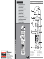
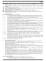
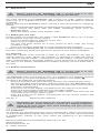
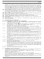
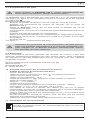
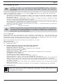
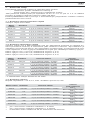
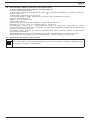
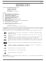
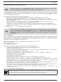
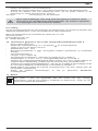
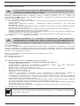
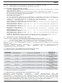
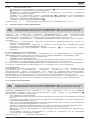
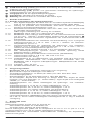
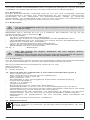
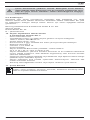
Bild 1: Gerätefrontseite
Fig. 1: Front tester panel
Fig. 1: Panneau avant de l‘appareil
Fig. 1: Parte frontal del equipo
obr. 1: Přední strana přístroje
σχήμα 1:
Μπροστινή όψη
ill. 1: Lato anteriore apparecchio
Fig. 1: Voorzijde van het apparaat
Rys. 1 Panel przedni przyrządu
Рис. 1. Фронтальная сторона прибора
Fig. 1: Framsida
Resim 1: Cihaz önyüzü

02/ 2006
BENNING CM 2
02/ 2006
BENNING CM 2
D F E I S D F E I S
02/ 2006
BENNING CM 2
D F E I S
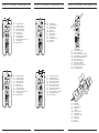
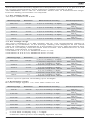
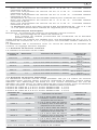
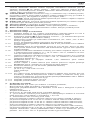
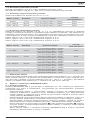
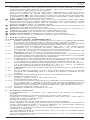
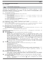
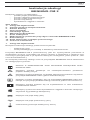
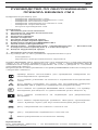
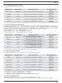
Bild 2: Gleichspannungsmessung
Fig. 2: DC voltage measurement
Fig. 2: Mesure de tension continue
obr. 2: Měření stejnosměrného napětí
Fig. 2: Medición de tensión contínua
σχήμα 2: μέτρηση DC-τάσης
ill. 2: Misura tensione continua
Fig. 2: Meten van gelijkspanning
Rys.2: Pomiar napięcia stałego
Рис. 2. Измерение напряжения постоянного тока
Fig. 2: Likspänningsmätning
Resim 2: Doğru Gerilim Ölçümü
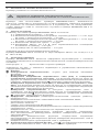
Bild 3: Wechselspannungsmessung
Fig. 3: AC voltage measurement
Fig. 3: Mesure de tension alternative
Fig. 3: Medición de tensión alterna
obr. 3: Měření střídavého napětí
σχήμα 3: μέτρηση AC-τάσης
ill. 3: Misura tensione alternata
Fig. 3: Meten van wisselspanning
Rys.3: Pomiar napięcia przemiennego
Рис. 3. Измерение напряжения переменного тока
Fig. 3: Växelspänningsmätning
Resim 3: Alternatif Gerilim Ölçümü
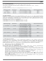
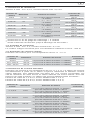
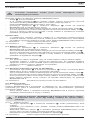
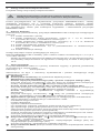
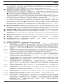
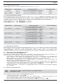
Bild 4: Widerstandsmessung
Fig. 4: Resistance measurement
Fig. 4: Mesure de résistance
Fig. 4: Medición de resistencia
obr. 4: Měření odporu
σχήμα 4: Μέτρηση αντίστασης
ill. 4: Misura di resistenza
Fig. 4: Weerstandsmeting
Rys.4: Pomiar rezystancji
Рис. 4. Измерение сопротивления
Fig. 4: Resistansmätning
Resim 4: Direnç Ölçümü
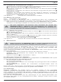
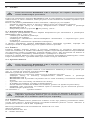
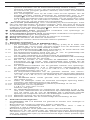
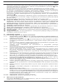
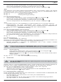
Bild 7: Batteriewechsel
Fig. 7: Battery replacement
Fig. 7: Remplacement des piles
Fig. 7: Cambio de pila
obr. 7: Výměna baterií
σχήμα 7: Αντικατάσταση μπαταριών
ill. 7: Sostituzione batterie
Fig. 7: Vervanging van de batterijen
Rys.7: Wymiana baterii
Рис. 7. Замена батарейки
Fig. 7: Batteribyte
Resim 7: Batarya Değişimi
Bild 5: Durchgangsprüfung mit Summer
Fig. 5: Continuity Testing with buzzer
Fig. 5: Contrôle de continuité avec ronfleur
Fig. 5: Control de continuidad con vibrador
Obr.5: Měření průchodnosti s bzučákem
σχήμα 5: Έλεγχος συνέχειας με ηχητικό σήμα
ill. 5: Prova di continuità con cicalino
Fig. 5: Doorgangstest met akoestisch signaal
Rys.5: Sprawdzenie ciągłości obwodu
Рис. 5. Контроль прохождения тока с зуммером
Fig. 5: Genomgångsmätning med summer
Resim 5: Sesli Süreklilik Ölçümü
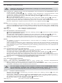
Bild 6: Gleich-/ Wechselstrommessung
Fig. 6: AC/ DC current measurement
Fig. 6: Mesure de courant continue/ courant alternatif
Fig. 6: Medición de corriente contínua/ corriente alterna
obr. 6: Měření stejnosměrného/ střídavého proudu
σχήμα 6: AC/ DC μέτρηση ρεύματος
ill. 6: Misura corrente continua/
alternata
Fig. 6: Meten van wissel- en gelijkstroom
Rys.6: Pomiar prądu stałego/ przemiennego
Рис. 6. Измерение постоянного и переменного тока
Fig. 6: Lik- och växelströmsmätning
Resim 6: Doğru Akım/ Alternatif Akım Ölçümü

02/ 2006
BENNING CM 2
1
D
Bedienungsanleitung
BENNING CM 2
Digital-Multimeter zur
- Wechselstrommessung
- Wechselspannungsmessung
- Gleichstrommessung
- Gleichspannungsmessung
- Widerstandsmessung
- Durchgangsprüfung
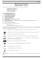
Inhaltsverzeichnis
1. Benutzerhinweise
2. Sicherheitshinweise
3. Lieferumfang
4. Gerätebeschreibung
5. Allgemeine Angaben
6. Umgebungsbedingungen
7. Elektrische Angaben
8. Messen mit dem BENNING CM 2
9. Instandhaltung
10. Technische Daten des Messzubehörs
11. Umweltschutz
1. Benutzerhinweise
Diese Bedienungsanleitung richtet sich an
- Elektrofachkräfte und
- elektrotechnisch unterwiesene Personen
Das BENNING CM 2 ist zur Messung in trockener Umgebung vorgesehen und
darf nicht in Stromkreisen mit einer höheren Nennspannung als 600 V einge-
setzt werden (Näheres hierzu in Abschnitt 6. “Umgebungsbedingungen”).
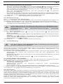
In der Bedienungsanleitung und auf dem BENNING CM 2 werden folgende
Symbole verwendet:
Anlegen um GEFÄHRLICH AKTIVE Leiter oder Abnehmen von
diesen ist zugelassen.
Dieses Symbol weist auf elektrische Gefahr hin.
Dieses Symbol weist auf Gefährdungen beim Gebrauch des
BENNING CM 2 hin. (Dokumentation beachten!)
Dieses Symbol auf dem BENNING CM 2 bedeutet, dass das Gerät
schutzisoliert (Schutzklasse II) ausgeführt ist.
Dieses Symbol erscheint in der Anzeige für eine entladene
Batterie.
Dieses Symbol kennzeichnet den Bereich “Durchgangsprüfung”.
Der Summer dient der akustischen Ergebnisausgabe.
(DC) Gleich- Spannung oder Strom.
(AC) Wechsel- Spannung oder Strom.
Masse (Spannung gegen Erde).
Hinweis
Nach Entfernen des Klebeschildes „Warnung...“ (auf dem Batteriedeckel) er-
scheint der englische Text!

02/ 2006
BENNING CM 2
2
D
2. Sicherheitshinweise
Beispiel für Sicherheitshinweis:
Elektrische Gefahr!
Beachten Sie die Sicherheitshinweise!
Bevor Sie das BENNING CM 2 benutzen, lesen Sie bitte die Bedienungsanleitung
sorgfältig. Beachten Sie die Sicherheitshinweise in der Bedienungsanleitung,
damit schützen Sie sich vor Unfällen und das BENNING CM 2 vor Schaden.
3. Lieferumfang
Zum Lieferumfang des BENNING CM 2 gehören:
3.1 ein Stück Digital-Multimeter,
3.2 ein Stück Sicherheitsmessleitung, schwarz (L = 1,4 m, Spitze Ø 4 mm)
mit Schutzkappen,
3.3 ein Stück Sicherheitsmessleitung, rot (L = 1,4 m, Spitze Ø 4 mm) mit
Schutzkappen,
3.4 eine Stück Kompakt-Schutztasche,
3.5 zwei Stück 1,5-V-Micro-Batterien (zur Erstbestückung im Multimeter
eingebaut),
3.6 eine Bedienungsanleitung.
Hinweis auf Verschleißteile:
Das BENNING CM 2 wird von zwei 1,5-V-Micro-Batterien (2 x 1,5-V-IEC LR 03)
gespeist.
- Die oben genannten Sicherheitsmessleitungen ATL-2 (geprüftes
Zubehör) entsprechen CAT III 1000 V und sind für einen Strom von 10 A
zugelassen.
4. Gerätebeschreibung
Das BENNING CM 2 ist ein Digital-Stromzangen-Multimeter mit einem
Hallsensor bestückten Strommesskopf
siehe Bild 1: Gerätefrontseite
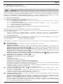
Die in Bild 1 angegebenen Anzeige- und Bedienelemente werden wie folgt
bezeichnet:
Gehäuse
Schiebeschalter, dient zur Wahl der gewünschten Funktionen.
- Aus (OFF)
- Wechselspannungsmessung (AC) und Gleichspannungsmessung
(DC), diese Funktionen wechseln auf Tastendruck der mit AC/DC
gekennzeichneten Funktionstaste einander ab. Die Digitalanzeige zeigt
die aktuelle Funktion an.
- Wechselstrommessung (AC) und Gleichstrommessung (DC), diese
Funktionen wechseln auf Tastendruck der mit AC/DC gekennzeichneten
Funktionstaste einander ab. Die Digitalanzeige zeigt die aktuelle
Funktion an.
- Widerstandsmessung, und Durchgangsprüfung mit Summer, diese Funktionen
wechseln auf Tastendruck der mit Ω/ gekennzeichneten Funktionstaste
einander ab. Die Digitalanzeige zeigt die aktuelle Funktion an.
Digitalanzeige (Flüssigkristallprinzip), angezeigt werden
- der Messwert mit der max. Anzeige 3999,
- die Polaritätsanzeige,
- der Dezimalpunkt,
- das Symbol für die entladene Batterie,
- die gewählte Spannungsart (Gleichspannung/ Wechselspannung),
- die gewählte Stromart (Gleichstrom/ Wechselstrom),
- der festgehaltene Messwert (Holdfunktion) oder der automatisch
festgehaltene Spitzenmesswert (MAX-Funktion)
- die gewählte Messfunktion durch Anzeige der erweiterten/ nicht erweiterten
Maßeinheiten von Spannung, Strom und Widerstand,
- die gewählte Durchgangsprüfung mit Summer,
Funktionstaste AC/DC - Ω/ , in der Digitalanzeige erscheinen dazu
“DC”; “AC”; “Ω”, “Summersymbol”
- zur Wahl zwischen Gleich-Spannungs/Strommessung (DC) und Wechsel-
Spannungs/Strommessung (AC) bzw.
- Widerstandsmessung und Durchgangsprüfung.
HOLD/ MAX-Taste (Haltefunktion und autom. Spitzenwertspeicherung),
- erster Tastendruck führt zum Halten des angezeigten Messwertes
(angezeigt durch “HOLD” in der Digitalanzeige , keine Aktualisierung des
Messwertes),

02/ 2006
BENNING CM 2
3
D
- erneuter Tastendruck führt zu fortlaufender Messung.
- Tastendruck (2 Sekunden) während des Einschaltens führt in die Funktion
Spitzenwertspeicherung (MAX). Kein weiterer Tastendruck führt zu
fortlaufender Messung.
- erster Tastendruck führt zum Speichern des Spitzenwertes während der
eingeschalteten Messzeit (angezeigt durch “MAX” in der Digitalanzeige )
Für alle Bereiche ausser Durchgangsprüfung. Rückschaltung (fortlaufende
Messung) durch Tastenbetätigung (2 Sekunden) der MAX-Taste.
Ausschalten der Funktion durch Gerät OFF.
ZERO-Taste (Nullabgleichstaste), zum Nullabgleich bei Strommessungen,
kann auch für alle Bereiche zur Differenzmessung benutzt werden
(Nullabgleich bei jedem Wert möglich!). Angezeigt durch “REL” in der
Digitalanzeige.
COM-Buchse, gemeinsame Buchse für Spannungs-, Widerstands-
messungen und Durchgangsprüfung, schwarz markiert.
V-Ω-Buchse (positive), gemeinsame Buchse für Spannungs-,
Widerstandsmessungen und Durchgangsprüfung, rot markiert.
Öffnungshebel, zum Öffnen und Schließen der Stromzange.
Stromzangenwulst, schützt vor Leiterberührung.
Messzange, zum Umfassen des einadrigen Stromdurchflossenen Leiters.
5. Allgemeine Angaben
5.1 Allgemeine Angaben zum Multimeter
5.1.1 Die Digitalanzeige ist als 3¾-stellige Flüssigkristallanzeige mit 13 mm
Schrifthöhe mit Dezimalpunkt ausgeführt. Der größte Anzeigewert ist
3999.
5.1.2 Die Polaritätsanzeige wirkt automatisch. Es wird nur eine Polung
entgegen der Buchsendefinition mit “-” angezeigt.
5.1.3 Die Bereichsüberschreitung wird mit "0L" oder "- 0L" und teilweise einer
akustischen Warnung angezeigt.
Achtung, keine Anzeige und Warnung bei Überlast!
5.1.4 Die Messrate der Ziffernanzeige des BENNING CM 2 beträgt nominal
ca. 2 Messungen pro Sekunde.
5.1.5 Das BENNING CM 2 schaltet nach ca. 30 min. selbstätig ab. Es
lässt sich nur durch betätigen des Schalters wieder einschalten. Ein
Summerton signalisiert die selbsttätige Abschaltung.
5.1.6 Temperaturkoeffizient des Messwertes für Spannungs- und
Widerstandsmessungen: 0,15 × (angegebene Messgenauigkeit)/ °C
< 18 °C oder > 28 °C, bezogen auf den Wert bei der Referenz-
temperatur von 23 °C.
5.1.7 Temperaturkoeffizient des Messwertes für Strommessungen: 0,2 ×
(angegebene Messgenauigkeit)/ °C < 20 °C oder > 26 °C, bezogen auf
den Wert bei der Referenztemperatur von 23 °C.
5.1.8 Das BENNING CM 2 wird durch zwei Stück 1,5-V-Batterien gespeist
(IEC LR03/ “Micro”).
5.1.9 Wenn die Batteriespannung unter die vorgesehene Arbeitsspannung des
BENNING CM 2 sinkt, erscheint in der Anzeige ein Batteriesymbol.
5.1.10 Die Lebensdauer der Batterien beträgt etwa 60 Stunden
(Alkalibatterie).
5.1.11 Geräteabmessungen: (L x B x H) = 192 x 66 x 27 mm
Gerätegewicht: 205 g
5.1.12 Die Sicherheitsmessleitungen mit den Messspitzen sind in 4 mm/ 2 mm-
Stecktechnik ausgeführt. Die mitgelieferten Sicherheitsmessleitungen
mit den Messspitzen sind ausdrücklich für die Nennspannung des
BENNING CM 2 geeignet. Die Messspitzen können durch Schutz-
kappen geschützt werden.
5.1.13 Größte Zangenöffnung: 25 mm
5.1.14 Größter Leitungsdurchmesser: 22 mm
6. Umgebungsbedingungen
- Das BENNING CM 2 ist nur für Messungen in trockener Umgebung
vorgesehen,
- Barometrische Höhe bei Messungen: Maximal 2000 m,
- Überspannungs-/ Aufstellungskategorie: IEC 664/ IEC 1010 600 V Kategorie
II (300 V Kategorie III),
- Verschmutzungsgrad: 2,
- Schutzart: IP 30 (DIN VDE 0470-1 IEC/ EN 60529)
3 - erste Kennziffer: Schutz gegen Zugang zu gefährlichen Teilen und
Schutz gegen feste Fremdkörper, > 2,5 mm Durchmesser
0 - zweite Kennziffer: Kein Wasserschutz,

02/ 2006
BENNING CM 2
4
D
- Arbeitstemperatur und relative Luftfeuchte für Spannungs- und
Widerstandsmessungen:
Bei Arbeitstemperatur von 0 °C bis 30 °C: relative Luftfeuchte kleiner 80 %,
Bei Arbeitstemperatur von 30 °C bis 40 °C: relative Luftfeuchte kleiner 75 %,
Bei Arbeitstemperatur von 40 °C bis 50 °C: relative Luftfeuchte kleiner 45 %,
- Arbeitstemperatur und relative Luftfeuchte für Strommessungen:
Bei Arbeitstemperatur von 0 °C bis 30 °C: relative Luftfeuchte kleiner 80 %,
Bei Arbeitstemperatur von 30 °C bis 40 °C: relative Luftfeuchte kleiner 75 %,
- Das BENNING CM 2 kann bei Temperaturen von - 20 °C bis + 60 °C gelagert
werden. Dabei sind die Batterien aus dem Gerät herauszunehmen.
7. Elektrische Angaben
Bemerkung: Die Messgenauigkeit wird angegeben als Summe aus
- einem relativen Anteil des Messwertes und
- einer Anzahl von Digit (d.h., Zahlenschritte der letzten Stelle).
Diese Messgenauigkeit gilt bei der Temperatur von 23 °C ± 5 °C (23 °C ± 3 °C
Strommessung) und einer relativen Luftfeuchtigkeit kleiner 80 %.
Das BENNING CM 2 arbeitet mit einer automatischen Messbereichsum-
schaltung, eine Voreinstellung ist somit nicht erforderlich.
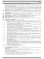
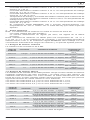
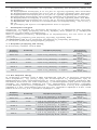
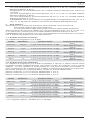
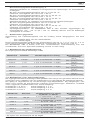
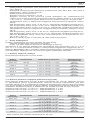
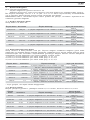
7.1 Gleichspannungsbereiche
Der Eingangswiderstand beträgt 9 MΩ.
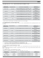
Messbereich Auflösung Messgenauigkeit Überlastschutz
400,0 mV 100 µV ± (0,5 % des Messwertes + 2 Digit) 600 Veff
600 V Gleichspannung
4,000 V 1 mV ± (0,5 % des Messwertes + 2 Digit) 600 Veff
600 V Gleichspannung
40,00 V 10 mV ± (0,5 % des Messwertes + 2 Digit) 600 Veff
600 V Gleichspannung
400,0 V 100 mV ± (0,5 % des Messwertes + 2 Digit) 600 Veff
600 V Gleichspannung
600 V 1 V ± (0,5 % des Messwertes + 2 Digit) 600 Veff
600 V Gleichspannung
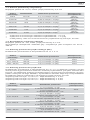
7.2 Wechselspannungsbereiche
Der Eingangswiderstand beträgt 9 MΩ parallel 100 pF. Der Messwert wird
durch Mittelwertgleichrichtung gewonnen und als Effektivwert angezeigt. Seine
Kalibrierung ist auf sinusförmige Kurvenform abgestimmt. Bei Abweichungen
von dieser Form wird der Anzeigewert ungenauer. So ergibt sich für folgende
Crest-Faktoren ein zusätzlicher Fehler:
Crest-Factor von 1,4 bis 2,0 zusätzlicher Fehler ± 1,0%
Crest-Factor von 2,0 bis 2,5 zusätzlicher Fehler ± 2,5%
Crest-Factor von 2,5 bis 3,0 zusätzlicher Fehler ± 4,0%
Messbereich Auflösung Messgenauigkeit Überlastschutz
400,0 mV 100 µV
± (2,0 % des Messwertes + 5 Digit)*
im Frequenzbereich 50 Hz - 60 Hz
600 Veff
600 V Gleichspannung
4,000 V 1 mV
± (1,5 % des Messwertes + 5 Digit)
im Frequenzbereich 40 Hz - 300 Hz
600 Veff
600 V Gleichspannung
40,00 V 10 mV
± (1,5 % des Messwertes + 5 Digit)
im Frequenzbereich 40 Hz - 500 Hz
600 Veff
600 V Gleichspannung
400,0 V 100 mV
± (1,5 % des Messwertes + 5 Digit)
im Frequenzbereich 40 Hz - 500 Hz
600 Veff
600 V Gleichspannung
600 V 1 V
± (1,5 % des Messwertes + 5 Digit)
im Frequenzbereich 40 Hz - 500 Hz
600 Veff
600 V Gleichspannung
* bei offenem Eingang, schwankend bis 30 Digit

02/ 2006
BENNING CM 2
5
D
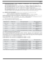
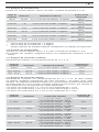
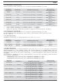
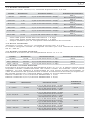
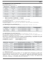
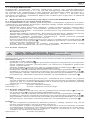
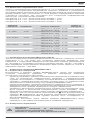
7.3 Widerstandsbereiche
Leerlaufspannung: ca. 0,3 V, max. Prüfstrom 0,2 mA.
Messbereich Auflösung Messgenauigkeit Überlastschutz
400 Ω 100 mΩ ± (1,2 % des Messwertes + 6 Digit)*1
600 Veff
600 V Gleichspannung
4,000 kΩ 1 Ω ± (0,9 % des Messwertes + 3 Digit)*2
600 Veff
600 V Gleichspannung
40,00 kΩ 10 Ω ± (0,9 % des Messwertes + 3 Digit)*2
600 Veff
600 V Gleichspannung
400,0 kΩ 100 Ω ± (1,2 % des Messwertes + 3 Digit)*2
600 Veff
600 V Gleichspannung
4,000 MΩ 1 kΩ ± (1,2 % des Messwertes + 3 Digit)*2
600 Veff
600 V Gleichspannung
40,00 MΩ 10 kΩ ± (2,5 % des Messwertes + 5 Digit)*1 *3
600 Veff
600 V Gleichspannung
*1 nur im Endbereich der Anzeige + 6 Digit
*2 nur im Endbereich der Anzeige + 3 Digit
*3 maximale Einlaufzeit bis zur Anzeige 20 Sekunden!
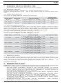
7.4 Durchgangsprüfung
Leerlaufspannung: ca. 3 V, max. Prüfstrom 0,7 mA.
Der eingebaute Summer ertönt bei einem Widerstand kleiner 50 Ω - 300 Ω.
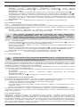
7.5 Gleichstrombereiche
Messgenauigkeit bei einer Temperatur von 23 °C ± 3 °C.
Messbereich Auflösung Messgenauigkeit Überlastschutz
40,00 A 10 mA ± (1,0 % des Messwertes + 2 Digit) 400 A
40,0 - 200,0 A 100 mA ± (1,0 % des Messwertes + 2 Digit) 400 A
200,0 - 300,0 A
100 mA ± (2,0 % des Messwertes + 2 Digit) 400 A
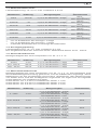
7.6 Wechselstrombereiche
Messgenauigkeit bei einer Temperatur von 23 °C ± 3 °C. Der Messwert wird
durch Mittelwertgleichrichtung gewonnen und als Effektivwert angezeigt. Seine
Kalibrierung ist auf sinusförmige Kurvenform abgestimmt. Bei Abweichungen
von dieser Form wird der Anzeigewert ungenauer. So ergibt sich für folgende
Crest-Faktoren ein zusätzlicher Fehler:
Crest-Factor von 1,4 bis 2,0 zusätzlicher Fehler ± 1,0%
Crest-Factor von 2,0 bis 2,5 zusätzlicher Fehler ± 2,5%
Crest-Factor von 2,5 bis 3,0 zusätzlicher Fehler ± 4,0%
Messbereich Auflösung Messgenauigkeit Überlastschutz
0 - 4,00 A 10 mA
± (1,0 % des Messwertes + 5 Digit)
bei Frequenzen 50 Hz - 60 Hz
± (2,0 % des Messwertes + 7 Digit)
bei Frequenzen 40 Hz - 1 kHz
400 A
4,00 - 40,00 A 10 mA
± (1,0 % des Messwertes + 3 Digit)
bei Frequenzen 50 Hz - 60 Hz
± (1,5 % des Messwertes + 5 Digit
bei Frequenzen 40 Hz - 1 kHz
400 A
40,0 - 200,0 A 100 mA
± (1,0 % des Messwertes + 3 Digit)
bei Frequenzen 50 Hz - 60 Hz
± (1,5 % des Messwertes + 5 Digit)
bei Frequenzen 40 Hz - 1 kHz
400 A
200,0 - 300,0 A
100 mA
± (3,0 % des Messwertes + 3 Digit)
bei Frequenzen 50 Hz - 60 Hz
± (5,0 % des Messwertes + 5 Digit)
bei Frequenzen 40 Hz - 1 kHz
400 A

02/ 2006
BENNING CM 2
6
D
7.7 Maximum HOLD
Die Messgenauigkeit der MAX-Holdanzeige beträgt angegebene Messge-
nauigkeit in % +10 Digit für den nächsten Messbereich. Beim Sprung in den
übernächsten Messbereich erhöht sich der Fehler auf +20 Digit usw. (Beispiel:
Ausgangswert 100 mV - 120V = + 30 Digit) Bei der Widerstandsmessung ist
eine MAX-Holdanzeige nur im Bereich von 400 Ω bis 400 kΩ gegeben.
8. Messen mit dem BENNING CM 2
8.1 Vorbereiten der Messungen
Benutzen und lagern Sie das BENNING CM 2 nur bei den angegebenen Lager- und
Arbeitstemperaturbedingungen, vermeiden Sie dauernde Sonneneinstrahlung.
- Angaben von Nennspannung und Nennstrom auf den Sicherheits-
messleitungen mit den Messspitzen überprüfen. Die zum Lieferumfang
gehörenden Sicherheitsmessleitungen mit den Messspitzen entsprechen in
Nennspannung und Nennstrom dem BENNING CM 2.
- Isolation der Sicherheitsmessleitungen mit den Messspitzen überprüfen.
Wenn die Isolation beschädigt ist, dann ist die Sicherheitsmessleitungen
sofort auszusondern.
- Sicherheitsmessleitungen auf Durchgang prüfen. Wenn der Leiter in der
Sicherheitsmessleitung unterbrochen ist, dann ist die Sicherheitsmess-
leitung sofort auszusondern.
- Bevor am Schiebeschalter oder der Funktionstaste eine andere
Funktion gewählt wird, müssen die Sicherheitsmessleitungen mit der
Messspitze von der Messstelle getrennt werden.
- Starke Störquellen in der Nähe der BENNING CM 2 können zu instabiler
Anzeige und zu Messfehlern führen.
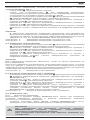
8.2 Spannungsmessung
Maximale Spannung gegen Erdpotential beachten!
Elektrische Gefahr!
Die höchste Spannung, die an den Buchsen des BENNING CM 2
- COM-Buchse , schwarz markiert,
- V--Buchse (positive) für Spannungs-, Widerstandsmessungen und
Durchgangsprüfungen, rot markiert, des BENNING CM 2 gegenüber
Erdpotential liegen darf, beträgt 600 V.
- Mit dem Schiebeschalter und der Funktionstaste des BENNING CM 2
die gewünschte Funktion wählen.
- Die schwarze Sicherheitsmessleitung mit der COM-Buchse , schwarz
gekennzeichnet, kontaktieren.
- Die rote Sicherheitsmessleitung mit der V-Ω-Buchse , rot gekenn-
zeichnet, kontaktieren.
- Die schwarze und die rote Messspitze mit den Messpunkten kontaktieren,
den Messwert an der Digitalanzeige ablesen.
Hinweis:
-
In kleinen Spannungsmessbereichen unterbleibt bei offenen Sicherheits-
messleitungen die Null-Volt-Anzeige durch Einstreuungen. Überzeugen Sie
sich durch Kurzschluss der Messspitzen davon, dass das BENNING CM 2
funktionsfähig ist.
siehe Bild 2: Gleichspannungsmessung
siehe Bild 3: Wechselspannungsmessung
8.3 Widerstandsmessung
- Mit dem Schiebeschalter und der Funktionstaste des BENNING CM 2
die gewünschte Funktion wählen.
- Die schwarze Sicherheitsmessleitung mit der COM-Buchse , schwarz
gekennzeichnet, kontaktieren.
- Die rote Sicherheitsmessleitung mit der V-Ω-Buchse , rot gekenn-
zeichnet, kontaktieren.
- Die schwarze und die rote Messspitze mit den Messpunkten kontaktieren,
den Messwert an der Digitalanzeige ablesen.
Hinweis:
- Stellen Sie für eine richtige Messung sicher, dass an der Messstelle keine
Spannung anliegt.
- Das Messergebnis bei kleinen Widerständen kann verbessert werden,
indem der Widerstand der Sicherheitsmessleitung zuvor mit Kurzschluss
der Messspitzen gemessen wird und der so gewonnene Widerstand vom
Ergebnis subtrahiert wird.
siehe Bild 4: Widerstandsmessung

02/ 2006
BENNING CM 2
7
D
8.4 Durchgangsprüfung mit Summer
- Mit dem Schiebeschalter und der Funktionstaste den mit dem Summer-
Symbol gekennzeichneten Bereich an dem BENNING CM 2 wählen.
- Die schwarze Sicherheitsmessleitung mit der COM-Buchse , schwarz
gekennzeichnet, kontaktieren.
- Die rote Sicherheitsmessleitung mit der V-Ω-Buchse , rot gekenn-
zeichnet, kontaktieren.
- Kontaktieren Sie die schwarze und die rote Messspitze mit den Messpunkten.
Wenn der Widerstand zwischen den Messpunkten 50 Ω unterschreitet, dann
ertönt der in dem BENNING CM 2 eingebaute Summer.
siehe Bild 5: Durchgangsprüfung mit Summer
8.5 Strommessung
8.5.1 Vorbereiten der Messungen
Benutzen und lagern Sie das BENNING CM 2 nur bei den angegebenen Lager- und
Arbeitstemperaturbedingungen, vermeiden Sie dauernde Sonneneinstrahlung.
- Starke Störquellen in der Nähe der BENNING CM 2 können zu instabiler
Anzeige und zu Messfehlern führen.
Keine Spannung an die Ausgangskontakte des BENNING CM 2
legen! Entfernen Sie eventuell die angeschlossenen Sicherheits-
messleitungen. Bei Gleichstrommessungen Polarität
beachten!
8.5.2 Strommessung
- Mit dem Schiebeschalter und der Funktionstaste die gewünschte
Messart wählen.
- Durch die Nullabgleichtaste „ZERO“ das BENNING CM 2 in Ausgangsposition
bringen.
- Öffnungshebel betätigen, einadrigen Leiter mit der Zange, des BENNING
CM 2 der den zu messenden Strom führt, umfassen.
- Die Digitalanzeige ablesen.
siehe Bild 6: Gleich-/ Wechselstrommessung
9. Instandhaltung
Vor dem Öffnen das BENNING CM 2 unbedingt spannungsfrei
machen! Elektrische Gefahr!
Die Arbeit an dem geöffneten BENNING CM 2 unter Spannung ist ausschließlich
Elektrofachkräften vorbehalten, die dabei besondere Maßnahmen zur
Unfallverhütung treffen müssen.
So machen Sie das BENNING CM 2 spannungsfrei, bevor Sie das Gerät öffnen:
- Entfernen Sie zuerst die schwarze und die rote Messspitze vom
Messobjekt.
- Entfernen Sie dann die schwarze die rote Sicherheitsmessleitung von dem
BENNING CM 2.
- Schalten Sie den Schiebeschalter in die Schaltstellung “OFF”.
9.1 Sicherstellen des Gerätes
Unter bestimmten Voraussetzungen kann die Sicherheit im Umgang mit dem
BENNING CM 2 nicht mehr gewährleistet sein; zum Beispiel bei:
- Sichtbaren Schäden am Gerät,
- Fehlern bei Messungen,
- Erkennbaren Folgen von längerer Lagerung unter unzulässigen
Bedingungen und
- Erkennbaren Folgen von außerordentlicher Transportbeanspruchung.
In diesen Fällen ist das BENNING CM 2 sofort abzuschalten, von der Messstelle
zu entfernen und gegen erneute Nutzung zu sichern.
9.2 Reinigung
Reinigen Sie das Gehäuse äußerlich mit einem sauberen und trockenen Tuch
(Ausnahme spezielle Reinigungstücher). Verwenden Sie keine Lösungs- und/
oder Scheuermittel, um den Spannungsprüfer zu reinigen. Achten Sie unbedingt
darauf, dass das Batteriefach und die Batteriekontakte nicht durch auslaufendes
Batterie-Elektrolyt verunreinigt werden.
Falls Elektrolytverunreinigungen oder weiße Ablagerungen im Bereich der
Batterie oder des Batteriegehäuses vorhanden sind, reinigen Sie auch diese
mit einen trockenem Tuch.

02/ 2006
BENNING CM 2
8
D
9.3 Batteriewechsel
Vor dem Öffnen das BENNING CM 2 unbedingt spannungsfrei
machen! Elektrische Gefahr!
Das BENNING CM 2 wird von zwei 1,5-V-Batterien gespeist. Batteriewechsel
(siehe Bild 8) ist dann erforderlich, wenn in der Anzeige das Batteriesymbol
erscheint.
So wechseln Sie die Batterien:
- Entfernen Sie die schwarze und die rote Messspitze vom Messkreis.
- Entfernen Sie die schwarze und die rote Sicherheitsmessleitung von dem
BENNING CM 2.
- Legen Sie das BENNING CM 2 auf die Frontseite und lösen Sie die
Schraube vom Batteriefachdeckel.
- Schieben Sie den Batteriefachdeckel zur Seite aus seiner Führung.
- Entfernen Sie die entladenen Batterien aus dem Batteriehalter.
- Legen Sie die neuen Batterien polrichtig in den Batteriehalter.
- Setzen Sie den Batteriefachdeckel auf und schieben ihn in die Endlage.
Montieren Sie die Schraube.
siehe Bild 7: Batteriewechsel
Leisten Sie Ihren Beitrag zum Umweltschutz! Batterien dürfen
nicht in den Hausmüll. Sie können bei einer Sammelstelle für
Altbatterien bzw. Sondermüll abgegeben werden. Informieren
Sie sich bitte bei Ihrer Kommune.
9.4 Kalibrierung
Um die angegebenen Genauigkeiten der Messergebnisse zu erhalten, muss das
Gerät regelmäßig durch unseren Werksservice kalibriert werden. Wir empfehlen
ein Kalibrierintervall von einem Jahr. Senden Sie hierzu das Gerät an folgende
Adresse:
Benning Elektrotechnik & Elektronik GmbH & Co. KG
Service Center
Robert-Bosch-Str. 20
D - 46397 Bocholt
10. Technische Daten des Messzubehörs
4 mm Sicherheitsmessleitung ATL 2
- Norm: EN 61010-031,
- Maximale Bemessungsspannung gegen Erde ( ) und Messkategorie:
1000 V CAT III, 600 V CAT IV,
- Maximaler Bemessungsstrom: 10 A,
- Schutzklasse II (), durchgängige doppelte oder verstärkte Isolierung,
- Verschmutzungsgrad: 2,
- Länge: 1,4 m, AWG 18,
- Umgebungsbedingungen:
Barometrische Höhe bei Messungen: Maximal 2000 m,
Temperatur: 0 °C bis + 50 °C, Feuchte 50 % bis 80 %
- Verwenden Sie die Messleitungen nur im einwandfreien Zustand und
entsprechend dieser Anleitung, da ansonsten der vorgesehene Schutz
beeinträchtigt sein kann.
- Sondern Sie die Messleitung aus, wenn die Isolierung beschädigt ist oder
eine Unterbrechung in Leitung/ Stecker vorliegt.
- Berühren Sie die Messleitung nicht an den blanken Kontaktspitzen. Fassen
Sie nur den Handbereich an!
- Stecken Sie die abgewinkelten Anschlüsse in das Prüf- oder Messgerät.
11. Umweltschutz
Bitte führen Sie das Gerät am Ende seiner Lebensdauer den zur
Verfügung stehenden Rückgabe- und Sammelsystemen zu.

02/ 2006
BENNING CM 2
9
Operating Manual
BENNING CM 2
Prong-Type Multimeter for
- alternating-current measurement
- AC-voltage measurement
- DC-current measurement
- resistance measurement
- continuity testing
Contents:
1. Notes for user
2. Notes on safety
3. Scope of supply
4. Description of unit
5. General data
6. Ambient conditions
7. Electrical data
8. Measuring with the BENNING CM 2
9. Maintenance
10. Technical data of the measuring accessories
11. Environmental notice
1. Notes for user
This Operating Manual is intended for:
- electricians and
- persons possessing knowledge of electrical technology.
The BENNING CM 2 is designed for measurements in dry surroundings and
must not be used in circuits with rated voltages higher than 600 V (for more
details, see section 6 “Ambient conditions”).
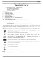
The following symbols are used in the Operating Manual and on the BENNING CM 2
itself:
Application around and removal from HAZARDOUS LIVE
conductors is permitted.
This symbol indicates an electrical hazard.
This symbol indicates sources of danger when using the
BENNING CM 2 (see documentation).
This symbol on the BENNING CM 2 indicates that the unit is
protection insulated (safety class II).
This symbol appears in the display for a discharged battery
This symbol indicates the continuity-testing application. The buzzer
provides an audible signal.
DC-voltage or current
AC-current or voltage
Earth (voltage to earth)
Note
After unmark the adhesive label „Warnung...“ (on battery compartment lid) the
English text appears.

02/ 2006
BENNING CM 2
10
2. Safety note
Example safety note:
Electrical hazard!
Comply with the safety instructions!
Before using the BENNING CM 2, read the operating instructions carefully.
Always comply with the safety notes given in the operating instructions. This is
essential in order to avoid accidents and damage to the BENNING CM 2.
3. Scope of supply
The following items make up the standard BENNING CM 2 package:
3.1 One digital multimeter
3.2 One safety measuring wire (black)(L = 1.4 m, tip Ø 4 mm) with safety caps.
3.3 One safety measuring wire (red)(L = 1.4 m, tip Ø 4 mm) with safety caps.
3.4 One compact protection case
3.5 Two 1.5 V micro-batteries (installed in the multimeter when supplied)
3.6 One Operating Manual
Note on consumable parts:
The BENNING CM 2 is supplied by two 1.5 V micro-batteries (2 x 1.5 V IEC LR 03)
- The above mentioned safety cable ATL 2 (tested spare part) are approved
in accordance with CAT III 1000 V and for a current up 10 A.
4. Description of tester unit
The BENNING CM 2 is a digital prong-type multimeter with a measuring head
fitted with a Hall sensor.
See fig. 1: Front panel
The display and operating elements shown in fig. 1 are as follows:
Housing
Sliding switch for selecting the required functions.
- OFF
- AC-voltage measurement (AC) and DC-voltage measurement (DC)
These functions alternate when the function button marked with AC/DC is
pressed. The digital display indicates the current function.
- AC-current measurement (AC) and DC-current measurement (DC)
These functions alternate when the function button marked with AC/DC is
pressed. The digital display indicates the current function.
- Resistance measurement and continuity measurement with buzzer
These functions alternate when the function button marked with / is
pressed. The digital display indicates the current function.
Digital display (liquid-crystal type) with following indications:
- measurement reading with max. indication 3999
- polarity indication
- decimal point
- symbol for discharged battery
- type of voltage selected (AC or DC voltage)
- type of current selected (AC or DC current)
- the measurement value retained (hold function) or the automatically
retained peak measurement value (MAX function)
- the measurement function selected by indication of the extended/non-
extended measurement units of current and resistance
- selected continuity test with buzzer.
Function button AC/DC - / . The digital display shows “DC”, “AC”,
“”, “buzzer symbol”.
- For selection between measurement of DC voltage/current or AC voltage/
current or
- Resistance measurement and continuity test.
HOLD/MAX button (hold function and automatic peak-value storage)
- The first press of the button causes the currently indicated measurement
value to be held (indicated by “HOLD” in the digital display , no updating
of measurement value).
- The second press of the button leads to continuous measurement.
- Pressing the button (for 2 sec.) during switch-on initiates the peak-value
storage (MAX) function. A second press of the button does not lead to
continuous measurement.
- The first press of the button causes the peak value during the switched-
on measuring time to be stored (indicated by “MAX” in the digital display
). For all ranges except continuity test. Switch back (continuous
measurement) by pressing MAX button (2 sec.).
- The function is switched off by pressing the OFF button.

02/ 2006
BENNING CM 2
11
ZERO button (zero setting button) for zero adjustment in current
measurement. Can also be used for all ranges for differential measurement
(zero setting possible for any value). Indicated by “REL” in the digital
display.
COM socket: joint socket for voltage and resistance measurements and
continuity test, marked black
V- Ω socket (positive): joint socket for voltage and resistance measurements
and continuity test, marked red
Opening lever, for opening and closing the current prongs
Prong guard, protects user from accidental contact with conductor
Measurement prongs, for inserting and gripping the single conductor
containing AC current.
5. General data
5.1 General data on multimeter
5.1.1 The digital display is designed as a 3 3/4 digit liquid-crystal indicator with 13
mm digit height and decimal point. The highest value displayed is 3999.
5.1.2 The polarity indication functions automatically. Contrary to the
measurement-wire definition, only one pole is indicated as “-”.
5.1.3 The range overload will be displayed with "OL" or "-OL" and sometimes
with an acoustic signal.
Attention: no display or warning by complete overload.
5.1.4 The nominal measuring rate of the digital display of the BENNING CM
2 is approx. 2 measurements per second.
5.1.5 The BENNING CM 2 switches off automatically after approx. 30 minutes.
It can only be switched on again by means of the switch. The buzzer
sounds to signal that the unit has switched off automatically.
5.1.6 Temperature coefficient of measurement value for voltage and
resistance measurements: 0.15 x (stated measurement accuracy)
°C < 18 °C or > 28 °C with reference to the value at the reference
temperature of 23 °C.
5.1.7 Temperature coefficient of measurement value for current measurements:
0.2 x (stated measurement accuracy) °C < 20 °C or > 26 °C with
reference to the value at the reference temperature of 23 °C.
5.1.8 The BENNING CM 2 is supplied by 2 1.5 V batteries (IEC LR03/
”Micro”).
5.1.9 When the battery voltage drops under the intended operating voltage of
the BENNING CM 2, a battery symbol appears in the display.
5.1.10 The service life of the battery is approx. 60 hours (alkali battery).
5.1.11 Dimensions of unit (length x width x height) = 192 x 66 x 27 mm.
Weight of unit: 205 g
5.1.12 The safety measuring wire and measurement tips are of the 4 mm/ 2
mm plug-in type. The safety measuring wires and measurement tips
supplied are specially suited to the rated voltage of the BENNING CM
2. The measuring tips can be protected by caps.
5.1.13 Widest prong opening: 25 mm
5.1.14 Largest wire diameter: 22 mm
6. Ambient conditions
- The BENNING CM 2 is designed only for measuring in dry surroundings.
- Maximum barometric height during measurement: 2000 m
- Overvoltage category / set-up category: IEC 664/ IEC 1010 600 V category II
(300 V category III).
- Degree of contamination: 2
- Protection Class: IP 30 (DIN VDE 0470-1 IEC/ EN 60529)
IP 30 means: Protection against access to dangerous parts and protection
against solid impurities of a diameter > 2.5 mm, (3 - first index). No
protection against water, (0 - second index).
- Operating temperature and relative humidity for voltage and resistance
measurements:
At operating temperature of 0 °C to 30 °C: relative humidity under 80%
At operating temperature of 30 °C to 40 °C: relative humidity under 75%
At operating temperature of 40 °C to 50 °C: relative humidity under 45%
- Operating temperature and relative humidity for current measurements:
At operating temperature of 0 °C to 30 °C: relative humidity under 80%
At operating temperature of 30 °C to 40 °C: relative humidity under 75%
- The BENNING CM 2 can be stored at temperatures from - 20 °C to + 60 °C.
The batteries must be removed from the unit.
7. Electrical data
Note: The measurement accuracy is stated as the sum of
- a relative proportion of the measurement value and
- a number of digits (i.e. numerical steps of the last place).

02/ 2006
BENNING CM 2
12
This measurement accuracy applies for a temperature of 23 °C ± 5 °C (23 °C ± 3 °C
for current measurement) and a maximum relative humidity of 80%.
The BENNING CM 2 has an automatic switch-over of measurement range.
Previous setting is therefore not required.
7.1 DC voltage range
The input resistance is 9 M.
Measuring range Resolution
Measurement accuracy
Overload protection
400,0 mV 100 µV ± (0,5 % of reading + 2 digits) 600 Veff
600 V DC voltage
4,000 V 1 mV ± (0,5 % of reading + 2 digits) 600 Veff
600 V DC voltage
40,00 V 10 mV ± (0,5 % of reading + 2 digits) 600 Veff
600 V DC voltage
400,0 V 100 mV ± (0,5 % of reading + 2 digits) 600 Veff
600 V DC voltage
600 V 1 V ± (0,5 % of reading + 2 digits) 600 Veff
600 V DC voltage
7.2 AC voltage range
The input resistance is 9 MΩ parallel 100 pF. The measurement reading is
obtained by rectification of the average reading and displayed as the actual
value. Its calibration is adapted for a sinusoidal curve form. With deviations from
this form, the display value becomes less accurate. The additional error for the
following crest factors is as follows:
crest factor of 1.4 to 2.0: additional error ± 1.0%
crest factor of 2.0 to 2.5: additional error ± 2.5%
crest factor of 2.5 to 3.0: additional error ± 4.0%
Measuring range Resolution
Measurement accuracy
Overload protection
400,0 mV 100 µV ± (2,0 % of reading + 5 digits)*
in frequency range 50 Hz - 60 Hz
600 Veff
600 V DC voltage
4,000 V 1 mV
± (1,5 % of reading + 5 digits)
in frequency range 40 Hz - 300 Hz
600 Veff
600 V DC voltage
40,00 V 10 mV
± (1,5 % of reading + 5 digits)
in frequency range 40 Hz - 500 Hz
600 Veff
600 V DC voltage
400,0 V 100 mV
± (1,5 % of reading + 5 digits)
in frequency range 40 Hz - 500 Hz
600 Veff
600 V DC voltage
600 V 1 V
± (1,5 % of reading + 5 digits)
in frequency range 40 Hz - 500 Hz
600 Veff
600 V DC voltage
* When input is opened, fluctuating up to 30 digits.
7.3 Resistance range
No-load voltage approx. 3 V, max. test current 0.1 mA
Measuring range Resolution
Measurement accuracy
Overload protection
400 Ω 100 mΩ
± (1,2 % of reading + 6 digits)*1 600 Veff
600 V DC voltage
4,000 kΩ 1 Ω
± (0,9 % of reading + 3 digit)*2 600 Veff
600 V DC voltage
40,00 kΩ 10 Ω
± (0,9 % of reading + 3 digit)*2 600 Veff
600 V DC voltage
400,0 kΩ 100 Ω
± (1,2 % of reading + 3 digit)*2 600 Veff
600 V DC voltage
4,000 MΩ 1 kΩ
± (1,2 % of reading + 3 digit)*2600 Veff
600 V DC voltage
40,00 MΩ 10 kΩ
± (2,5 % of reading + 5 digit)*1 *3 600 Veff
600 V DC voltage
*1 in end area of display only, + 6 digits
*2 in end area of display only, + 3 digits
*3 maximum start-up time until display appears, 20 sec.

02/ 2006
BENNING CM 2
13
7.4 Continuity test
No-load voltage approx. 3 V, max. test current 0.7 mA
The built-in buzzer sounds when resistance is less than 50 Ω - 300 Ω.
7.5 DC ranges
Measurement accuracy at a temperature of 23 °C ± 3 °C
Measuring range Resolution
Measurement accuracy
Overload protection
40,0 A 10 mA ± (1,0 % of reading + 2 digit) 400 A
40,0 - 200,0 A 100 mA ± (1,0 % of reading + 2 digit) 400 A
200,0 - 300,0 A 100 mA ± (2,0 % of reading + 2 digit) 400 A
7.6 AC ranges
Measurement accuracy at a temperature of 23 °C ± 3 °C. The measurement
reading is obtained by rectification of average reading and displayed as actual
value. Its calibration is adapted for a sinusoidal curve form. With deviations from
this form, the display value becomes less accurate. The additional error for the
following crest factors is as follows:
crest factor of 1.4 to 2.0: additional error ± 1.0%
crest factor of 2.0 to 2.5: additional error ± 2.5%
crest factor of 2.5 to 3.0: additional error ± 4.0%
Measuring range Resolution
Measurement accuracy
Overload protection
0 - 4,0 A 10 mA
± (1,0 % of reading + 5 digit)
for frequencies 50 - 60 Hz
± (2,0 % of reading + 7 digit)
for frequencies 40 - 1 Hz
400 A
4,00 - 40,00 A 10 mA
± (1,0 % of reading + 3 digit)
for frequencies 50 Hz - 60 Hz
± (1,5 % of reading + 5 digit
for frequencies 40 Hz - 1 kHz
400 A
40,0 - 200,0 A 100 mA
± (1,0 % of reading + 3 digit)
for frequencies 50 Hz - 60 Hz
± (1,5 % of reading + 5 digit)
for frequencies 40 Hz - 1 kHz
400 A
200,0 - 300,0 A 100 mA
± (3,0 % of reading + 3 digit)
for frequencies 50 Hz - 60 Hz
± (5,0 % of reading + 5 digit)
for frequencies 40 Hz - 1 kHz
400 A
7.7 Maximum HOLD
The measuring accuracy of the MAX-Hold display is the stated measuring
accuracy in % + 10 digits for the next measuring range. When passing to the
measuring range after next, the error increases to + 20 digits etc. (Example:
starting figure 100 mV - 120 V = + 30 digits). When measuring resistance, a
MAX hold indication is only possible in the range from 400 to 400 k.
8. Measuring with the BENNING CM 2
8.1 Preparation for measurement
Store and use the BENNING CM 2 only under the correct temperature
conditions stated. Always avoid longer exposure to sunlight.
- Check the rated voltage and current stated on the safety measuring wires
with tips. The rated voltage and current of the safety measuring wires and
tips comply with the BENNING CM 2.
- Check the insulation of the measuring wires and tips. If the insulation is
damaged, replace the testing measuring wires immediately.
- Check the continuity of the safety measuring wires. If the wire is
disconnected at any point, remove it immediately.
- Before selecting another function with the sliding switch or the function
button , the safety measuring wires and tips must be disconnected from
the measuring point.
- Strong sources of interference close to the BENNING CM 2 may produce
unstable readings and measurement errors.

02/ 2006
BENNING CM 2
14
8.2 Voltage measurement
Always observe the maximum voltage to earth potential!
Electrical hazard!
The maximum voltage which may be applied to the sockets of the BENNING CM 2
- COM socket, black ,
- V- socket (positive) for voltage and resistance measurements and
continuity testing (marked red) against earth potential, is 600 V.
- Select the desired function with the sliding switch and the function button
of the BENNING CM 2.
- Contact the black safety measuring wire with the COM-socket (black).
- Contact the red safety measuring wire with the V- socket (red).
- Bring the black and red measuring tips into contact with the measurement
points. Read the measurement value on the digital display .
Note:
- In small voltage measuring ranges, the zero-volt indication does not appear
(due to interference) when the safety measuring wires are open. Make sure
that the BENNING CM 2 is fully functional by short-circuiting the measuring
tips.
See fig. 2: DC-voltage measurement
See fig. 3: AC-voltage measurement
8.3 Resistance measurement
- Select the desired function with the sliding switch and the function button
of the BENNING CM 2.
- Contact the black safety measuring wire with the COM-socket (black).
- Contact the red safety measuring wire with the V- socket (red).
- Bring the black and red measuring tips into contact with the measurement
points. Read the measurement value on the digital display .
Note:
- To obtain a correct measurement, ensure that no voltage is applied to the
measuring point.
- With small resistances, the measuring result can be improved by measuring
the resistance of the safety measuring wires beforehand by short-circuiting
the measuring tips and subtracting the reading obtained from the resistance
measured.
See fig. 4: Resistance measurement
8.4 Continuity testing with buzzer
- Select the area marked with the buzzer symbol with the sliding switch
and the function button of the BENNING CM 2.
- Contact the black safety measuring wire with the COM-socket (black).
- Contact the red safety measuring wire with the V- socket (red).
- Bring the black and red measuring tips into contact with the measurement
points. If the resistance between the measurement points is less than 50 ,
the buzzer incorporated in the BENNING CM 2 sounds.
See fig. 5: Continuity testing with buzzer
8.5 Current measurement
8.5.1 Preparation for measurement
Store and use the BENNING CM 2 only under the correct temperature
conditions stated. Always avoid long exposure to sunlight.
- Strong sources of interference close to the BENNING CM 2 may produce
unstable readings and measurement errors.
Do not apply voltage to the output contacts of the BENNING CM 2.
If necessary, remove the safety measuring wires connected.
When measuring DC current, observe correct polarity.
8.5.2 Current measurement
- Select the desired measuring function with the sliding switch and the
function button .
- Press the “ZERO” button to set the BENNING CM 2 to the starting point.
- Operate the opening lever . Grip the single wire containing the current to
be measured with the prongs of the BENNING CM 2.
- Read the value in the digital display .
See fig. 6: AC/ DC current measurement

02/ 2006
BENNING CM 2
15
9. Maintenance
Before opening the BENNING CM 2, ensure that it is not
connected to a source of voltage! Electrical hazard!
Any work required on the BENNING CM 2 when it is under voltage must be
done only by a qualified electrician. Special steps must be taken to prevent
accidents.
Before opening the BENNING CM 2, remove it from all sources of voltage as
follows:
- Remove first the black and the red measuring tip from the measurement object.
- Then remove the black and red safety measuring wires from the
BENNING CM 2.
- Move the sliding switch to the position “OFF”.
9.1 Making the unit safe
Under certain circumstances, the safety of the BENNING CM 2 can no longer
be guaranteed. This may be the case if:
- there are visible signs of damage on the unit,
- errors occur in measurements,
- the unit has been stored for a long period of time under the wrong
conditions, and
- if the unit has been subjected to rough handling during transport.
In these cases, the BENNING CM 2 must be switched off immediately, removed
from the measuring points and secured to prevent it from being used again.
9.2 Cleaning
Clean the outside of the unit with a clean dry cloth. (Exception: any type of
special cleaning cloth). Never use solvents or abrasives to clean the testing
unit. Ensure that the battery compartment and the battery contacts have not
been contaminated by electrolyte leakage. If any electrolyte or white deposits
are seen in the battery compartment or battery housing, remove these with a
dry cloth.
9.3 Battery replacement
Before opening the BENNING CM 2, ensure that it is not
connected to a source of voltage! Electrical hazard!
The BENNING CM 2 is powered by two 1.5 V batteries. The batteries must be
replaced (see fig. 8) when the battery symbol appears in the display .
To replace the batteries, proceed as follows:
- Remove the black and red measuring tips from the measurement circuit.
- Remove the black and red safety measuring wires from the BENNING CM 2.
- Lay the BENNING CM 2 on its front and unscrew the screw on the cover of
the battery compartment.
- Push the cover of the battery compartment to the side out of its guide.
- Remove the discharged batteries from the battery holder.
- Insert the new batteries into the battery holder. Make sure that they are
connected to the correct battery poles.
- Push the cover of the battery compartment into its correct position and
replace the screw.
See fig. 7: Replacing the batteries.
Remember the environment! Do not dispose of used batteries
with domestic waste. Dispose of them at a battery-collection
point or as toxic waste. Your local authority will give you the
information you need.
9.4 Calibration
To maintain the specified precision of the measurement results, the instrument
must be recalibrated at regular intervals by our factory service. We recommend
a recalibration interval of one year. Send the appliance to the following
address:
Benning Elektrotechnik & Elektronik GmbH & CO. KG
Service Centre
Robert-Bosch-Str. 20
D - 46397 Bocholt

02/ 2006
BENNING CM 2
16
10. Technical data of the measuring accessories
4 mm Safety test leads ATL 2
- Standard: EN 61010-031,
- Maximum rated voltage to earth ( ) and measuring category:
1000 V CAT III, 600 V CAT IV,
- Maximum rated current: 10 A,
- Protective class II (), continuous double or reinforced insulation,
- Contamination class: 2,
- Length: 1.4 m, AWG 18,
- Environmental conditions:
Maximum barometric elevation for making measurements: 2000 m,
Temperatures: 0 °C to + 50 °C, humidity 50 % to 80 %
- Only use the test leads if in perfect condition and according to this manual,
since the protection provided could otherwise be impaired.
- Throw the test leads out if the insulation is damaged or if there is a break in
the cable/ plug.
- Do not touch the bare contact tips of the test leads. Only grab the area
appropriate for hands!
- Insert the angled terminals in the testing or measuring device.
11. Environmental notice
At the end of the product’s useful life, please dispose of it at
appropriate collection points provided in your country.

02/ 2006
BENNING CM 2
17
F
Notice d’utilisation
BENNING CM 2
Multimètre numérique pour
- mesures de courant alternatif
- mesures de tension alternative
- mesures de courant continu
- mesures de courant alternative
- mesures de résistance
- contrôles de continuité
Sommaire :
1. Instructions d’utilisation
2. Instructions de sécurité
3. Composition de l’appareil
4. Description de l’appareil
5. Caractéristiques générales
6. Conditions d’environnement
7. Caractéristiques électriques
8. Mesures avec le BENNING CM 2
9. Maintenance
10. Données techniques des accessoires de mesure
11. Information sur l’environnement
1. Instructions d’utilisation
Cette notice d’utilisation s’adresse aux
- électriciens et
- aux personnes ayant reçu une formation en électrotechnique.
Le BENNING CM 2 est destiné aux mesures en milieu sec et ne doit pas être
utilisé sur des circuits de tension nominale supérieure à 600 V (voir aussi le
paragraphe 6. « Conditions d’environnement »).
Les symboles suivants sont utilisés dans la notice d’utilisation ainsi que sur le
BENNING CM 2 lui-même :
Permet le déplacement et l’application autours d’un conducteur actif
non isolé.
Ce symbole indique un danger d’électrocution.
Ce symbole indique un risque pour l’utilisateur lors de la manipulation
du BENNING CM 2 (Observer la notice !)
Ce symbole placé sur le BENNING CM 2 signifie que l’appareil est
réalisé en version isolée (classe de protection II).
Ce symbole apparaît sur l’affichage lorsque les piles sont
déchargées.
Ce symbole caractérise la fonction « Contrôle de continuité ». Le
ronfleur sert de résultat acoustique.
(DC) Tension ou courant continus.
(AC) Tension ou courant alternatifs.
Masse (Tension par rapport à la terre).
Instructions
Le texte en anglais apparaît en enlevant l’étiquette autocollante «Warnung...»
(située sur le capot batterie).

02/ 2006
BENNING CM 2
18
F
2. Instructions de sécurité
Exemple d’instructions de sécurité :
Danger d’électrocution
Observer les instructions de sécurité !
Etudier soigneusement la notice d’utilisation avant d’utiliser le BENNING CM 2.
Observer les instructions de sécurité de la notice d’utilisation pour vous protéger
contre les accidents et éviter d’endommager le BENNING CM 2.
3. Composition de l’appareil
Le BENNING CM 2 comprend les éléments suivants :
3.1 un multimètre numérique,
3.2 un conducteur de mesure de sécurité noir (L = 1,4 m, pointe 4 mm)
avec capuchon de protection,
3.3 un conducteur de mesure de sécurité rouge (L = 1,4 m, pointe 4 mm)
avec capuchon de protection,
3.4 un étui de protection compact,
3.5 deux micro-piles de 1,5 V (déjà installées dans le multimètre),
3.6 une notice d’utilisation.
En ce qui concerne les éléments consommables :
Le BENNING CM 2 est alimenté par deux piles de 1,5 V (2 x type CIE LR 03
1,5 V).
- Les câbles de mesure de sécurité ATL 2 (accessoires contrôlés) mentionnés
ci-dessus correspondent à CAT III 1000 V et sont homologués pour un
courant de 10 A.
4. Description de l’appareil
Le BENNING CM 2 est un multimètre numérique à pince électrique avec une
tête de mesure de courant équipée d’un détecteur Hall.
voir figure 1 : face avant de l’appareil.
Les éléments de commande et d’affichage représentés sur la figure 1 sont
désignés comme suit :
Boîtier
Sélecteur à curseur, permet de choisir la fonction voulue.
- Eteint (OFF)
- Mesure de tension alternative (AC) et mesure de tension continue
(DC), on bascule entre ces fonctions par pression de la touche de fonction
identifiée par AC/DC. L’affichage numérique indique la fonction utilisée.
- Mesure de courant alternatif (AC) et mesure de courant continu (DC),
on bascule entre ces fonctions par pression de la touche de fonction
identifiée par AC/DC. L’affichage numérique indique la fonction utilisée.
- Mesure de résistance et contrôle de continuité avec ronfleur, on bascule
entre ces fonctions par pression de la touche de fonction identifiée par Ω/
. L’affichage numérique indique la fonction utilisée.
Affichage numérique (à cristaux liquides) indique
- la valeur mesurée avec 3999 comme valeur maximale,
- l’affichage de polarité,
- le point décimal,
- le symbole de pile déchargée,
- le type de tension sélectionné (tension continue/ tension alternative),
- le type de courant sélectionné (courant continu/ courant alternatif),
- la valeur de mesure retenue (fonction Hold) ou la valeur de mesure de
pointe automatiquement retenue (fonction MAX)
- la fonction de mesure choisie par affichage de l’unité de mesure étendue/
non étendue de la tension, du courant et de la résistance
- le contrôle de continuité sélectionné avec ronfleur,
Touche de fonction AC/DC - Ω/ , l’affichage numérique indique à cet
effet « DC » ; « AC » ; « Ω », « Symbole du ronfleur »
- pour la sélection entre la mesure de courant/ tension continus (DC) et la
mesure de courant/ tension alternatifs (AC) ou encore
- la mesure de résistance et le contrôle de continuité.
Touche HOLD/ MAX (fonction de retenue et mise en mémoire automatique
de la valeur de pointe),
- une première pression de la touche entraîne la retenue de la valeur affichée
(indiquée par « HOLD » sur l’affichage numérique , pas d’actualisation de
la valeur de mesure),
- une nouvelle pression de la touche reprend la mesure en cours.
La pagina sta caricando ...
La pagina sta caricando ...
La pagina sta caricando ...
La pagina sta caricando ...
La pagina sta caricando ...
La pagina sta caricando ...
La pagina sta caricando ...
La pagina sta caricando ...
La pagina sta caricando ...
La pagina sta caricando ...
La pagina sta caricando ...
La pagina sta caricando ...
La pagina sta caricando ...
La pagina sta caricando ...
La pagina sta caricando ...
La pagina sta caricando ...
La pagina sta caricando ...
La pagina sta caricando ...
La pagina sta caricando ...
La pagina sta caricando ...
La pagina sta caricando ...
La pagina sta caricando ...
La pagina sta caricando ...
La pagina sta caricando ...
La pagina sta caricando ...
La pagina sta caricando ...
La pagina sta caricando ...
La pagina sta caricando ...
La pagina sta caricando ...
La pagina sta caricando ...
La pagina sta caricando ...
La pagina sta caricando ...
La pagina sta caricando ...
La pagina sta caricando ...
La pagina sta caricando ...
La pagina sta caricando ...
La pagina sta caricando ...
La pagina sta caricando ...
La pagina sta caricando ...
La pagina sta caricando ...
La pagina sta caricando ...
La pagina sta caricando ...
La pagina sta caricando ...
La pagina sta caricando ...
La pagina sta caricando ...
La pagina sta caricando ...
La pagina sta caricando ...
La pagina sta caricando ...
La pagina sta caricando ...
La pagina sta caricando ...
La pagina sta caricando ...
La pagina sta caricando ...
La pagina sta caricando ...
La pagina sta caricando ...
La pagina sta caricando ...
La pagina sta caricando ...
La pagina sta caricando ...
La pagina sta caricando ...
La pagina sta caricando ...
La pagina sta caricando ...
La pagina sta caricando ...
La pagina sta caricando ...
La pagina sta caricando ...
La pagina sta caricando ...
La pagina sta caricando ...
La pagina sta caricando ...
La pagina sta caricando ...
La pagina sta caricando ...
La pagina sta caricando ...
La pagina sta caricando ...
La pagina sta caricando ...
La pagina sta caricando ...
La pagina sta caricando ...
La pagina sta caricando ...
La pagina sta caricando ...
La pagina sta caricando ...
La pagina sta caricando ...
La pagina sta caricando ...
-
 1
1
-
 2
2
-
 3
3
-
 4
4
-
 5
5
-
 6
6
-
 7
7
-
 8
8
-
 9
9
-
 10
10
-
 11
11
-
 12
12
-
 13
13
-
 14
14
-
 15
15
-
 16
16
-
 17
17
-
 18
18
-
 19
19
-
 20
20
-
 21
21
-
 22
22
-
 23
23
-
 24
24
-
 25
25
-
 26
26
-
 27
27
-
 28
28
-
 29
29
-
 30
30
-
 31
31
-
 32
32
-
 33
33
-
 34
34
-
 35
35
-
 36
36
-
 37
37
-
 38
38
-
 39
39
-
 40
40
-
 41
41
-
 42
42
-
 43
43
-
 44
44
-
 45
45
-
 46
46
-
 47
47
-
 48
48
-
 49
49
-
 50
50
-
 51
51
-
 52
52
-
 53
53
-
 54
54
-
 55
55
-
 56
56
-
 57
57
-
 58
58
-
 59
59
-
 60
60
-
 61
61
-
 62
62
-
 63
63
-
 64
64
-
 65
65
-
 66
66
-
 67
67
-
 68
68
-
 69
69
-
 70
70
-
 71
71
-
 72
72
-
 73
73
-
 74
74
-
 75
75
-
 76
76
-
 77
77
-
 78
78
-
 79
79
-
 80
80
-
 81
81
-
 82
82
-
 83
83
-
 84
84
-
 85
85
-
 86
86
-
 87
87
-
 88
88
-
 89
89
-
 90
90
-
 91
91
-
 92
92
-
 93
93
-
 94
94
-
 95
95
-
 96
96
-
 97
97
-
 98
98


in altre lingue
- Türkçe: Benning CM2 El kitabı
Documenti correlati
-
Benning CM6 Manuale del proprietario
-
-
-
-
-
Benning ST 710 Istruzioni per l'uso
-
-
-
Benning Duspol Analog Istruzioni per l'uso