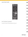
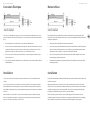
Behringer 992 CONTROL VOLTAGES Guida Rapida
- Tipo
- Guida Rapida

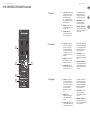
Quick Start Guide
992 CONTROL VOLTAGES
Legendary Analog CV Routing Module for Eurorack
V 3.0

2 3Quick Start Guide992 CONTROL VOLTAGES
(EN) Safety Instruction
1. Read these instructions.
2. Keep these instructions.
3. Heed all warnings.
4. Follow all instructions.
5. Do not use this apparatus near water.
6. Clean only with dry cloth.
7. Do not block any ventilation openings. Install in
accordance with the manufacturer’s instructions.
8. Do not install near any heat sources such as
radiators, heat registers, stoves, or other apparatus
(including amplifiers) that produce heat.
9. Use only attachments/accessories specified by
the manufacturer.
10. Use only with the cart, stand, tripod,
bracket, or table specified by the
manufacturer, or sold with the apparatus.
When a cart is used, use caution when moving the
cart/apparatus combination to avoid injury from
tip-over.
11. Correct disposal of this product: This symbol
indicates that this product must not be
disposed of with household waste,
according to the WEEE Directive (2012/19/EU) and
your national law. This product should be taken to a
collection center licensed for the recycling of waste
electrical and electronic equipment (EEE). The
mishandling of this type of waste could have a
possible negative impact on the environment and
human health due to potentially hazardous
substances that are generally associated with EEE. At
the same time, your cooperation in the correct
disposal of this product will contribute to the efficient
use of natural resources. For more information about
where you can take your waste equipment for
recycling, please contact your local city office, or your
household waste collection service.
12. Do not install in a confined space, such as a book
case or similar unit.
13. Do not place naked flame sources, such as lighted
candles, on the apparatus.
(ES) Instrucción de seguridad
1. Lea las instrucciones.
2. Conserve estas instrucciones.
3. Preste atención a todas las advertencias.
4. Siga todas las instrucciones.
5. No use este aparato cerca del agua.
6. Limpie este aparato con un paño seco.
7. No bloquee las aberturas de ventilación. Instale
el equipo de acuerdo con las instrucciones del
fabricante.
8. No instale este equipo cerca de fuentes de calor
tales como radiadores, acumuladores de calor, estufas
u otros aparatos (incluyendo amplificadores) que
puedan producir calor.
9. Use únicamente los dispositivos o accesorios
especificados por el fabricante.
10. Use únicamente la carretilla, plataforma,
trípode, soporte o mesa especificados por el
fabricante o suministrados junto con el
equipo. Al transportar el equipo,
tenga cuidado para evitar daños y caídas al tropezar
con algún obstáculo.
11. Cómo debe deshacerse de este aparato: Este
símbolo indica que este aparato no debe ser
tratado como basura orgánica, según lo
indicado en la Directiva WEEE (2012/19/EU) y a las
normativas aplicables en su país. En lugar de ello
deberá llevarlo al punto limpio más cercano para el
reciclaje de sus elementos eléctricos / electrónicos
(EEE). Al hacer esto estará ayudando a prevenir las
posibles consecuencias negativas para el medio
ambiente y la salud que podrían ser provocadas por
una gestión inadecuada de este tipo de aparatos.
Además, el reciclaje de materiales ayudará a conservar
los recursos naturales. Para más información acerca del
reciclaje de este aparato, póngase en contacto con el
Ayuntamiento de su ciudad o con el punto limpio local.
12. No instale esta unidad en un espacio
muy reducido, tal como encastrada en una
librería o similar.
13. No coloque objetos con llama, como una vela
encendida, sobre este aparato.
(FR) Consignes de sécurité
1. Lisez ces consignes.
2. Conservez ces consignes.
3. Respectez tous les avertissements.
4. Respectez toutes les consignes d’utilisation.
5. N’utilisez jamais l’appareil à proximité d’un liquide.
6. Nettoyez l’appareil avec un chiffon sec.
7. Veillez à ne pas empêcher la bonne ventilation de
l’appareil via ses ouïes de ventilation. Respectez les
consignes du fabricant concernant l’installation de
l’appareil.
8. Ne placez pas l’appareil à proximité d’une source
de chaleur telle qu’un chauffage, une cuisinière ou
tout appareil dégageant de la chaleur (y compris un
ampli de puissance).
9. Utilisez exclusivement des accessoires et des
appareils supplémentaires recommandés par le
fabricant.
10. Utilisez exclusivement des chariots, des
diables, des présentoirs, des pieds et des
surfaces de travail recommandés par le
fabricant ou livrés avec le produit.
Déplacez précautionneusement tout chariot ou diable
chargé pour éviter d’éventuelles blessures en cas de
chute.
11. Mise au rebut appropriée de ce produit: Ce
symbole indique qu’en accord avec la
directive DEEE (2012/19/EU) et les lois en
vigueur dans votre pays, ce produit ne doit pas être
jeté avec les déchets ménagers. Ce produit doit être
déposé dans un point de collecte agréé pour le
recyclage des déchets d’équipements électriques et
électroniques (EEE). Une mauvaise manipulation de ce
type de déchets pourrait avoir un impact négatif sur
l’environnement et la santé à cause des substances
potentiellement dangereuses généralement associées
à ces équipements. En même temps, votre
coopération dans la mise au rebut de ce produit
contribuera à l’utilisation efficace des ressources
naturelles. Pour plus d’informations sur l’endroit où
vous pouvez déposer vos déchets d’équipements pour
le recyclage, veuillez contacter votre mairie ou votre
centre local de collecte des déchets.
12. N’installez pas l’appareil dans un espace confiné
tel qu’une bibliothèque ou meuble similaire.
13. Ne placez jamais d’objets enflammés, tels que des
bougies allumées, sur l’appareil.
(DE) Wichtige Sicherhteitshinweise
1. Lesen Sie diese Hinweise.
2. Bewahren Sie diese Hinweise auf.
3. Beachten Sie alle Warnhinweise.
4. Befolgen Sie alle Bedienungshinweise.
5. Betreiben Sie das Gerät nicht in der Nähe von
Wasser.
6. Reinigen Sie das Gerät mit einem trockenen Tuch.
7. Blockieren Sie nicht die Belüftungsschlitze.
Beachten Sie beim Einbau des Gerätes die
Herstellerhinweise.
8. Stellen Sie das Gerät nicht in der Nähe von
Wärmequellen auf. Solche Wärmequellen sind z. B.
Heizkörper, Herde oder andere Wärme erzeugende
Geräte (auch Verstärker).
9. Verwenden Sie nur Zusatzgeräte/Zubehörteile,
die laut Hersteller geeignet sind.
10. Verwenden Sie nur Wagen,
Standvorrichtungen, Stative, Halter oder
Tische, die vom Hersteller benannt oder im
Lieferumfang des Geräts enthalten sind. Falls Sie
einen Wagen benutzen, seien Sie vorsichtig beim
Bewegen der Wagen- Gerätkombination, um
Verletzungen durch Stolpern zu vermeiden.
11. Korrekte Entsorgung dieses Produkts:
Dieses Symbol weist darauf hin, das Produkt
entsprechend der WEEE Direktive (2012/19/
EU) und der jeweiligen nationalen Gesetze nicht
zusammen mit Ihren Haushaltsabfällen zu entsorgen.
Dieses Produkt sollte bei einer autorisierten
Sammelstelle für Recycling elektrischer und
elektronischer Geräte (EEE) abgegeben werden.
Wegen bedenklicher Substanzen, die generell mit
elektrischen und elektronischen Geräten in
Verbindung stehen, könnte eine unsachgemäße
Behandlung dieser Abfallart eine negative
Auswirkung auf Umwelt und Gesundheit haben.
Gleichzeitig gewährleistet Ihr Beitrag zur richtigen

4 5Quick Start Guide992 CONTROL VOLTAGES
Entsorgung dieses Produkts die effektive Nutzung
natürlicher Ressourcen. Für weitere Informationen zur
Entsorgung Ihrer Geräte bei einer Recycling-Stelle
nehmen Sie bitte Kontakt zum zuständigen
städtischen Büro, Entsorgungsamt oder zu Ihrem
Haushaltsabfallentsorger auf.
12. Installieren Sie das Gerät nicht in einer beengten
Umgebung, zum Beispiel Bücherregal oder ähnliches.
13. Stellen Sie keine Gegenstände mit offenen
Flammen, etwa brennende Kerzen, auf das Gerät.
(PT) Instruções de Segurança
Importantes
1. Leia estas instruções.
2. Guarde estas instruções.
3. Preste atenção a todos os avisos.
4. Siga todas as instruções.
5. Não utilize este dispositivo perto de água.
6. Limpe apenas com um pano seco.
7. Não obstrua as entradas de ventilação. Instale de
acordo com as instruções do fabricante.
8. Não instale perto de quaisquer fontes de calor tais
como radiadores, bocas de ar quente, fogões de sala
ou outros aparelhos (incluindo amplificadores) que
produzam calor.
9. Utilize apenas ligações/acessórios especificados
pelo fabricante.
10. Utilize apenas com o carrinho, estrutura,
tripé, suporte, ou mesa especificados pelo
fabricante ou vendidos com o dispositivo.
Quando utilizar um carrinho, tenha cuidado ao mover
o conjunto carrinho/dispositivo para evitar danos
provocados pela terpidação.
11. Correcta eliminação deste produto: este
símbolo indica que o produto não deve ser
eliminado juntamente com os resíduos
domésticos, segundo a Directiva REEE (2012/19/EU) e
a legislação nacional. Este produto deverá ser levado
para um centro de recolha licenciado para a
reciclagem de resíduos de equipamentos eléctricos e
electrónicos (EEE). O tratamento incorrecto deste tipo
de resíduos pode ter um eventual impacto negativo
no ambiente e na saúde humana devido a substâncias
potencialmente perigosas que estão geralmente
associadas aos EEE. Ao mesmo tempo, a sua
colaboração para a eliminação correcta deste produto
irá contribuir para a utilização eficiente dos recursos
naturais. Para mais informação acerca dos locais onde
poderá deixar o seu equipamento usado para
reciclagem, é favor contactar os serviços municipais
locais, a entidade de gestão de resíduos ou os serviços
de recolha de resíduos domésticos.
12. Não instale em lugares confinados, tais como
estantes ou unidades similares.
13. Não coloque fontes de chama, tais como velas
acesas, sobre o aparelho.
(IT) Istruzioni di sicurezza
importanti
1. Leggere queste istruzioni.
2. Conservare queste istruzioni.
3. Prestare attenzione a tutti gli avvisi.
4. Applicare tutte le istruzioni.
5. Non utilizzare questo dispositivo vicino l'acqua.
6. Pulire esclusivamente con un panno asciutto.
7. Non bloccare le aperture di ventilazione. Installare
in conformità con le istruzioni del produttore.
8. Non installare vicino a fonti di
calore come radiatori, termoregolatori,
stufe o altri apparecchi (inclusi amplificatori) che
producono calore.
9. Utilizzare esclusivamente dispositivi/accessori
specificati dal produttore.
10. Utilizzare solo carrelli, supporti, treppiedi,
staffe o tavoli indicati dal produttore o
venduti con l'apparecchio. Utilizzando un
carrello, prestare attenzione quando si sposta la
combinazione carrello/apparecchio per evitare lesioni
dovute al ribaltamento.
11. Smaltimento corretto di questo prodotto:
questo simbolo indica che questo dispositivo
non deve essere smaltito insieme ai rifiuti
domestici, secondo la Direttiva RAEE (2012/19 / UE) e
la vostra legislazione nazionale. Questo prodotto deve
essere portato in un centro di raccolta autorizzato per
il riciclaggio di rifiuti di apparecchiature elettriche ed
elettroniche (RAEE). La cattiva gestione di questo tipo
di rifiuti potrebbe avere un possibile impatto negativo
sull'ambiente e sulla salute umana a causa di sostanze
potenzialmente pericolose che sono generalmente
associate alle apparecchiature elettriche ed
elettroniche. Nello stesso tempo la vostra
collaborazione al corretto smaltimento di questo
prodotto contribuirà all'utilizzo efficiente delle risorse
naturali. Per ulteriori informazioni su dove è possibile
trasportare le apparecchiature per il riciclaggio vi
invitiamo a contattare l'ufficio comunale locale o il
servizio di raccolta dei rifiuti domestici.
12. Non installare in uno spazio ristretto, come in una
libreria o in una struttura simile.
13. Non collocare sul dispositivo fonti di fiamme
libere, come candele accese.
(NL) Belangrijke
veiligheidsvoorschriften
1. Lees deze voorschriften.
2. Bewaar deze voorschriften.
3. Neem alle waarschuwingen in acht.
4. Volg alle voorschriften op.
5. Gebruik dit apparaat niet in de buurt van water.
6. Reinig het uitsluitend met een droge doek.
7. Let erop geen van de ventilatie-openingen
te bedekken. Plaats en installeer het volgens de
voor- schriften van de fabrikant.
8. Het apparaat mag niet worden geplaatst in de
buurt van radiatoren, warmte-uitlaten, kachels of
andere zaken (ook versterkers) die warmte afgeven.
9. Gebruik uitsluitend door de producent
gespeci- ficeerd toebehoren c.q. onderdelen.
10. Gebruik het apparaat uitsluitend in
combinatie met de wagen, het statief, de
driepoot, de beugel of tafel die door de
producent is aangegeven, of die in combinatie met
het apparaat wordt verkocht. Bij gebruik van een
wagen dient men voorzichtig te zijn bij het verrijden
van de combinatie wagen/apparaat en letsel door
vallen te voorkomen.
11. Correcte afvoer van dit product: dit symbool
geeft aan dat u dit product op grond van de
AEEA-richtlijn (2012/19/EU) en de nationale
wetgeving van uw land niet met het gewone
huishoudelijke afval mag weggooien. Dit product
moet na afloop van de nuttige levensduur naar een
officiële inzamelpost voor afgedankte elektrische en
elektronische apparatuur (AEEA) worden gebracht,
zodat het kan worden gerecycleerd. Vanwege de
potentieel gevaarlijke stoffen die in elektrische en
elektronische apparatuur kunnen voorkomen, kan
een onjuiste afvoer van afval van het onderhavige
type een negatieve invloed op het milieu en de
menselijke gezondheid hebben. Een juiste afvoer van
dit product is echter niet alleen beter voor het milieu
en de gezondheid, maar draagt tevens bij aan een
doelmatiger gebruik van de natuurlijke hulpbronnen.
Voor meer informatie over de plaatsen waar u uw
afgedankte apparatuur kunt inleveren, kunt u contact
opnemen met uw gemeente of de plaatselijke
reinigingsdienst.
12. Installeer niet in een kleine ruimte, zoals een
boekenkast of iets dergelijks.
13. Plaats geen open vlammen, zoals brandende
kaarsen, op het apparaat.
(SE) Viktiga säkerhetsanvisningar
1. Läs dessa anvisningar.
2. Spara dessa anvisningar.
3. Beakta alla varningar.
4. Följ alla anvisningar.
5. Använd inte apparaten i närheten av vatten.
6. Rengör endast med torr trasa.
7. Blockera inte ventilationsöppningarna. Installera
enligt tillverkarens anvisningar.
8. Installera aldrig intill värmekällor som
värme- element, varmluftsintag, spisar eller annan
utrustning som avger värme (inklusive förstärkare).
9. Använd endast tillkopplingar och tillbehör som
angetts av tillverkaren.
10. Använd endast med vagn, stativ, trefot,
hållare eller bord som angetts av
tillverkaren, eller som sålts till-sammans

6 7Quick Start Guide992 CONTROL VOLTAGES
med apparaten. Om du använder en vagn, var
försiktig, när du förflyttar kombinationen vagn-
apparat, för att förhindra olycksfall genom snubbling.
11. Kassera produkten på rätt sätt: den här
symbolen indikerar att produkten inte ska
kastas i hushållssoporna, enligt WEEE
direktivet (2012/19/EU) och gällande, nationell
lagstiftning. Produkten ska lämnas till ett
auktoriserat återvinningsställe för elektronisk och
elektrisk utrustning (EEE). Om den här sortens avfall
hanteras på fel sätt kan miljön, och människors hälsa,
påverkas negativt på grund av potentiella
risksubstanser som ofta associeras med EEE.
Avfallshanteras produkten däremot på rätt sätt bidrar
detta till att naturens resurser används på ett bra
sätt. Kontakta kommun, ansvarig förvaltning eller
avfallshanteringsföretag för mer information om
återvinningscentral där produkten kan lämnas.
12. Installera inte i ett trångt utrymme, t.ex. i en
bokhylsa eller liknande enhet.
13. Placera inte källor med öppen eld, t.ex. tända ljus,
på apparaten.
(PL) Ważne informacje o
bezpieczeństwie
1. Proszę przeczytać poniższe wskazówki.
2. Proszę przechowywać niniejszą instrukcję.
3. Należy przestrzegać wszystkich wskazówek
ostrzegawczych.
4. Należy postępować zgodnie z instrukcją obsługi.
5. Urządzenia nie wolno używać w pobliżu wody.
6. Urządzenie można czyścić wyłącznie suchą szmatką.
7. Nie zasłaniać otworów wentylacyjnych. W
czasie podłączania urządzenia należy przestrzegać
zaleceń producenta.
8. Nie stawiać urządzenia w pobliżu źródeł ciepła
takich, jak grzejniki, piece lub urządzenia produkujące
ciepło (np. wzmacniacze).
9. Używać wyłącznie sprzętu dodatkowego i
akcesoriów zgodnie z zaleceniami producenta.
10. Używać jedynie zalecanych przez
producenta lub znajdujących się w zestawie
wózków, stojaków, statywów, uchwytów i
stołów. W przypadku posługiwania się wózkiem
należy zachować szczególną ostrożność w trakcie
przewożenia zestawu, aby uniknąć
niebezpieczeństwa potknięcia się i zranienia.
11. Prawidłowa utylizacja produktu: Ten
symbol wskazuje, że tego produktu nie
należy wyrzucać razem ze zwykłymi
odpadami domowymi, tylko zgodnie z dyrektywą w
sprawie zużytego sprzętu elektrycznego i
elektronicznego (WEEE) (2012/19/EU) oraz przepisami
krajowymi. Niniejszy produkt należy przekazać do
autoryzowanego punktu zbiórki zużytego sprzętu
elektrycznego i elektronicznego. Niewłaściwe
postępowanie z tego typu odpadami może wywołać
szkodliwe działanie na środowisko naturalnej i
zdrowie człowieka z powodu potencjalnych substancji
niebezpiecznych zaliczanych jako zużyty sprzęt
elektryczny i elektroniczny. Jednocześnie, Twój wkład
w prawidłową utylizację niniejszego produktu
przyczynia się do oszczędnego wykorzystywania
zasobów naturalnych. Szczegółowych informacji o
miejscach, w których można oddawać zużyty sprzęt
do recyklingu, udzielają urzędy miejskie,
przedsiębiorstwa utylizacji odpadów lub najbliższy
zakład utylizacji odpadów.
12. Nie instaluj w ograniczonej przestrzeni, takiej jak
półka na książki lub podobny zestaw.
13. Nie stawiaj na urządzeniu źródeł otwartego
ognia, takich jak zapalone świece.
(JP) 安全指示
1.
2.
3.
4.
5.
6.
7.
8.
9.
10.
11.
WEEE2012/19 / EU
EEE
EEE
12.
13.
(CN) 安全须知
1. 请阅读这些说明。
2. 请妥善保存这些说明。
3. 请注意所有的警示。
4. 请遵守所有的说明。
5. 请勿在靠近水的地方使用本产品。
6. 请用干布清洁本产品。
7. 请勿堵塞通风孔, 安装本产品时请遵照
厂家的说明, 通风孔不要覆盖诸如报纸、桌
布和窗帘等物品而妨碍通风。
8. 请勿将本产品安装在热源附近, 如暖气
片, 炉子或其它产生热量的设备 (包括功放
器)。 产品上不要放置裸露的火焰源, 如点燃
的蜡烛。
9. 请只使用厂家指定的附属设备和配 件。
10. 请只使用厂家指定的或随货销售
的手推车, 架子, 三 角架, 支架和
桌子。 若使用手推车来搬运设备, 请注意安
全放置设备, 以 避免手推车和设备倾倒而受
伤。
11. 如果液体流入或异物落入设备内, 设备
遭雨淋或受潮, 设备不能正常运作或被摔坏
等, 设备受损需进行维修时, 所有维修均须
由合格的维修人员进行维修。

8 9Quick Start Guide992 CONTROL VOLTAGES
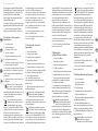
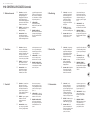
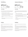
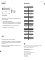
992 CONTROL VOLTAGES Controls
(1)
(4)
(5)
(2) (3)
(FR) Réglages
(1) CV Switches – Allow the voltage
or signal from the associated
input to be sent to the output
jacks when the switch is in
the up position. The input is
disconnected when the switch is
in the down position.
(2) EXT INPUT – Additional input to
be used with the signal-inverting
attenuator circuit.
(3) Attenuator Knob - Turn
clockwise to adjust the CV level
from 0 to 10 (unity gain). Turn
counterclockwise to invert the
signal from 0 to -10, which is
also unity gain. At the center 0
position, the signal is off (-∞).
(4) CONTROL INPUTS – Connect
control voltages from other
modules via 3.5 mm TS cable.
(5) FREQUENCY CONTROL TO LPF –
Send the combined voltage from
all 4 inputs to up to 3 modules via
3.5 mm TS cable.
(1) CV Switches – Permita que el
voltaje o la señal de la entrada
asociada se envíe a las tomas
de salida cuando el interruptor
esté en la posición hacia arriba.
La entrada se desconecta cuando
el interruptor está en la posición
hacia abajo.
(2) EXT INPUT – Entrada adicional
para ser utilizada con el circuito
atenuador inversor de señal.
(3) Attenuator Knob - Gire en el
sentido de las agujas del reloj para
ajustar el nivel de CV de 0 a 10
(ganancia unitaria). Gire en sentido
antihorario para invertir la señal de
0 a -10, que también es ganancia
unitaria. En la posición 0 central,
la señal está apagada (-∞).
(4) CONTROL INPUTS – Conecte
las tensiones de control de otros
módulos mediante un cable TS de
3,5 mm.
(5) FREQUENCY CONTROL TO LPF –
Envíe la tensión combinada de las
4 entradas hasta un máximo de
3 módulos mediante un cable TS
de 3,5 mm.
(EN) Controls
(ES) Controles
(1) CV Switches – Permettre à la
tension ou au signal de l’entrée
associée d’être envoyé aux prises
de sortie lorsque le commutateur
est en position haute. L’entrée
est déconnectée lorsque
l’interrupteur est en position
basse.
(2) EXT INPUT – Entrée
supplémentaire à utiliser avec le
circuit d’atténuateur inverseur
de signal.
(3) Attenuator Knob - Tournez dans
le sens des aiguilles d’une montre
pour régler le niveau CV de 0 à 10
(gain unitaire). Tournez dans le
sens inverse des aiguilles d’une
montre pour inverser le signal de
0 à -10, qui est également un gain
unitaire. En position centrale 0,
le signal est désactivé (-∞).
(4) CONTROL INPUTS – Connectez
les tensions de commande
d’autres modules via un câble TS
de 3,5 mm.
(5) FREQUENCY CONTROL TO LPF –
Envoyez la tension combinée des 4
entrées à 3 modules maximum via
un câble TS de 3,5 mm.

10 11Quick Start Guide992 CONTROL VOLTAGES
(IT) Controlli (PL) Sterowanica
(1) CV Switches – Lassen Sie die
Spannung oder das Signal vom
zugehörigen Eingang an die
Ausgangsbuchsen senden, wenn
sich der Schalter in der oberen
Position befindet. Der Eingang wird
getrennt, wenn sich der Schalter in
der unteren Position befindet.
(2) EXT INPUT – Zusätzlicher Eingang
für die signalinvertierende
Dämpfungsschaltung.
(3) Attenuator Knob - Drehen
Sie im Uhrzeigersinn, um den
CV-Pegel von 0 bis 10 einzustellen
(Einheitsverstärkung). Drehen Sie
gegen den Uhrzeigersinn, um das
Signal von 0 auf -10 zu invertieren.
Dies ist auch eine Verstärkung von
eins. In der mittleren 0-Position ist
das Signal ausgeschaltet (-∞).
(4) CONTROL INPUTS –
Steuerspannungen anderer
Module über ein 3,5 mm TS-Kabel
anschließen.
(5) FREQUENCY CONTROL TO
LPF – Senden Sie die kombinierte
Spannung von allen 4 Eingängen
über ein 3,5 mm TS-Kabel an bis
zu 3 Module.
(1) CV Switches – Sta toe dat de
spanning of het signaal van de
bijbehorende ingang naar de
uitgangsaansluitingen wordt
gestuurd als de schakelaar
omhoog staat. De ingang is
losgekoppeld als de schakelaar
omlaag staat.
(2) EXT INPUT – Extra ingang
voor gebruik met het signaal-
inverterende verzwakkingscircuit.
(3) Attenuator Knob - Draai met
de klok mee om het CV-niveau
aan te passen van 0 tot 10
(eenheidswinst). Draai tegen
de klok in om het signaal om te
keren van 0 naar -10, wat ook een
eenheidsversterking is. Op de
middelste 0-positie is het signaal
uit (-∞).
(4) CONTROL INPUTS – Sluit
stuurspanningen van andere
modules aan via 3,5 mm TS-kabel.
(5) FREQUENCY CONTROL TO
LPF – Stuur de gecombineerde
spanning van alle 4 ingangen naar
maximaal 3 modules via 3,5 mm
TS-kabel.
(1) CV Switches – Permita que
a tensão ou o sinal da entrada
associada seja enviado para as
tomadas de saída quando a chave
estiver na posição para cima.
A entrada é desconectada quando
a chave está na posição para baixo.
(2) EXT INPUT – Entrada adicional
para ser usada com o circuito
atenuador de inversão de sinal.
(3) Attenuator Knob - Gire no
sentido horário para ajustar o
nível de CV de 0 a 10 (ganho
de unidade). Gire no sentido
anti-horário para inverter o sinal
de 0 a -10, que também é ganho
de unidade. Na posição central 0,
o sinal está desligado (-∞).
(4) CONTROL INPUTS – Conecte as
tensões de controle de outros
módulos via cabo TS de 3,5 mm.
(5) FREQUENCY CONTROL TO LPF –
Envie a tensão combinada de todas
as 4 entradas para até 3 módulos
via cabo TS de 3,5 mm.
(1) CV Switches – Låt spänningen
eller signalen från tillhörande
ingång skickas till utgångarna
när strömställaren är i uppläge.
Ingången kopplas bort när
omkopplaren är i nedåtläge.
(2) EXT INPUT – Ytterligare
ingång som ska användas
med den signalinverterande
dämpningskretsen.
(3) Attenuator Knob - Vrid medurs
för att justera CV-nivån från
0 till 10 (enhetsförstärkning).
Vrid moturs för att invertera
signalen från 0 till -10, vilket också
är enhetsförstärkning. Vid mitt
0-position är signalen avstängd
(-∞).
(4) CONTROL INPUTS – Anslut
styrspänningar från andra
moduler via 3,5 mm TS-kabel.
(5) FREQUENCY CONTROL TO
LPF – Skicka den kombinerade
spänningen från alla 4 ingångarna
till upp till 3 moduler via 3,5 mm
TS-kabel.
(DE) Bedienelemente (NL) Bediening
(PT) Controles (SE) Kontroller
(1) CV Switches – Consentire l’invio
della tensione o del segnale
dall’ingresso associato ai jack di
uscita quando l’interruttore è in
posizione sollevata. L’ingresso è
scollegato quando l’interruttore è
in posizione abbassata.
(2) EXT INPUT – Ingresso aggiuntivo
da utilizzare con il circuito
attenuatore di inversione
del segnale.
(3) Attenuator Knob - Girare in
senso orario per regolare il livello
CV da 0 a 10 (guadagno unitario).
Girare in senso antiorario per
invertire il segnale da 0 a -10, che
è anche guadagno unitario. Nella
posizione 0 centrale, il segnale è
spento (-∞).
(4) CONTROL INPUTS – Collegare le
tensioni di controllo di altri moduli
tramite un cavo TS da 3,5 mm.
(5) FREQUENCY CONTROL TO LPF –
Invia la tensione combinata da
tutti e 4 gli ingressi a un massimo
di 3 moduli tramite cavo TS da
3,5 mm.
(1) CV Switches – Pozwól,
aby napięcie lub sygnał ze
skojarzonego wejścia były
wysyłane do gniazd wyjściowych,
gdy przełącznik znajduje się
w górnym położeniu. Wejście
jest odłączane, gdy przełącznik
znajduje się w dolnym położeniu.
(2) EXT INPUT – Dodatkowe wejście
do wykorzystania z obwodem
tłumika odwracającego sygnał.
(3) Attenuator Knob - Obróć
zgodnie z ruchem wskazówek
zegara, aby wyregulować poziom
CV od 0 do 10 (wzmocnienie
jedności). Obróć w lewo,
aby odwrócić sygnał od 0 do -10,
co jest również wzmocnieniem
jedności. W środkowej pozycji 0
sygnał jest wyłączony (-∞).
(4) CONTROL INPUTS – Podłączyć
napięcia sterujące z innych
modułów za pomocą kabla TS
3,5 mm.
(5) FREQUENCY CONTROL TO
LPF – Wyślij połączone napięcie
ze wszystkich 4 wejść do
maksymalnie 3 modułów za
pomocą kabla TS 3,5 mm.
992 CONTROL VOLTAGES Controls

12 13Quick Start Guide992 CONTROL VOLTAGES
992 CONTROL VOLTAGES Controls
(1) CV Switches –
(2) EXT INPUT –
(3) Attenuator Knob –
CV 0
10
0 -10
0
-∞
(4) CONTROL INPUTS – 3.5 mm TS
(5) FREQUENCY CONTROL TO LPF –
3.5 mm TS
4 3
(JP) コントロール
(1) CV Switches – 当开关处于向上
位置时, 允许将来自相关输入
的电压或信号发送到输出插
孔。 当开关处于向下位置时,
输入断开。
(2) EXT INPUT – 与信号反相衰减
器电路一起使用的附加输入。
(3) Attenuator Knob – 顺时针旋
转可将 CV 电平从 0 调整到 10 (
单位增益)。 逆时针旋转可将
信号从 0 反转为 -10, 这也是
单位增益。 在中心 0 位置, 信
号关闭 ( -∞ )。
(4) CONTROL INPUTS – 通过 3.5
mm TS 电缆连接其他模块的
控制电压。
(5) FREQUENCY CONTROL TO LPF –
通过 3.5 mm TS 电缆将来自所
有 4 个输入的组合电压发送
至最多 3 个模块。
(CN) 控制

14 15Quick Start Guide992 CONTROL VOLTAGES
Conexión Eléctrica
Instalación
El 992 viene con el cable de alimentación necesario para conectarse a un sistema de alimentación estándar Eurorack. Siga estos pasos para
conectar la alimentación al módulo. Es más fácil realizar estas conexiones antes de que el módulo se haya montado en una caja de rack.
1. Apague la fuente de alimentación o la caja del bastidor y desconecte el cable de alimentación.
2. Inserte el conector de 16 clavijas del cable de alimentación en la toma de la fuente de alimentación o en la caja del bastidor.
El conector tiene una pestaña que se alineará con el espacio en el zócalo, por lo que no se puede insertar incorrectamente. Si la
fuente de alimentación no tiene un enchufe con llave, asegúrese de orientar el pin 1 (-12 V) con la raya roja en el cable.
3. Inserte el conector de 10 pines en el zócalo en la parte posterior del módulo. El conector tiene una pestaña que se alineará con el
enchufe para una orientación correcta.
4. Una vez que ambos extremos del cable de alimentación se hayan conectado de forma segura, puede montar el módulo en una caja
y encender la fuente de alimentación.
Los tornillos necesarios se incluyen con el módulo para su montaje en una caja Eurorack. Conecte el cable de alimentación antes
del montaje.
Dependiendo de la caja del bastidor, puede haber una serie de orificios fijos separados 2 HP a lo largo de la caja, o una pista que permita
que las placas roscadas individuales se deslicen a lo largo de la caja. Las placas roscadas de movimiento libre permiten un posicionamiento
preciso del módulo, pero cada placa debe colocarse en una relación aproximada con los orificios de montaje en su módulo antes de colocar
los tornillos.
Sostenga el módulo contra los rieles Eurorack de modo que cada uno de los orificios de montaje esté alineado con un riel o placa roscada.
Coloque los tornillos parcialmente para comenzar, lo que permitirá pequeños ajustes en la posición mientras los alinea todos. Una vez
establecida la posición final, apriete los tornillos.
Power Connection
Installation
The 992 comes with the required power cable for connecting to a standard Eurorack power supply system. Follow these steps to connect
power to the module. It is easier to make these connections before the module has been mounted into a rack case.
1. Turn the power supply or rack case power off and disconnect the power cable.
2. Insert the 16-pin connector on the power cable into the socket on the power supply or rack case. The connector has a tab that will
align with the gap in the socket, so it cannot be inserted incorrectly. If the power supply does not have a keyed socket, be sure to
orient pin 1 (-12 V) with the red stripe on the cable.
3. Insert the 10-pin connector into the socket on the back of the module. The connector has a tab that will align with the socket for
correct orientation.
4. After both ends of the power cable have been securely attached, you may mount the module in a case and turn on the
power supply.
The necessary screws are included with the module for mounting in a Eurorack case. Connect the power cable before mounting.
Depending on the rack case, there may be a series of fixed holes spaced 2 HP apart along the length of the case, or a track that allows
individual threaded plates to slide along the length of the case. The free-moving threaded plates allow precise positioning of the module,
but each plate should be positioned in the approximate relation to the mounting holes in your module before attaching the screws.
Hold the module against the Eurorack rails so that each of the mounting holes are aligned with a threaded rail or threaded plate.
Attach the screws part way to start, which will allow small adjustments to the positioning while you get them all aligned. After the final
position has been established, tighten the screws down.

16 17Quick Start Guide992 CONTROL VOLTAGES
Netzanschluss
Installation
Der 992 wird mit dem erforderlichen Stromkabel für den Anschluss an ein Standard-Eurorack-Stromversorgungssystem geliefert.
Befolgen Sie diese Schritte, um das Modul mit Strom zu versorgen. Es ist einfacher, diese Verbindungen herzustellen, bevor das Modul in
ein Rackgehäuse eingebaut wurde.
1. Schalten Sie das Netzteil oder das Rackgehäuse aus und ziehen Sie das Netzkabel ab.
2. Stecken Sie den 16-poligen Stecker am Netzkabel in die Buchse am Netzteil oder im Rack-Gehäuse. Der Anschluss verfügt über eine
Lasche, die an der Lücke in der Buchse ausgerichtet ist, sodass sie nicht falsch eingesetzt werden kann. Wenn das Netzteil keine
Schlüsselbuchse hat, achten Sie darauf, Pin 1 (-12 V) mit dem roten Streifen am Kabel auszurichten.
3. Stecken Sie den 10-poligen Stecker in die Buchse auf der Rückseite des Moduls. Der Anschluss verfügt über eine Lasche, die zur
korrekten Ausrichtung an der Buchse ausgerichtet wird.
4. Nachdem beide Enden des Netzkabels fest angeschlossen wurden, können Sie das Modul in einem Gehäuse montieren und die
Stromversorgung einschalten.
Die erforderlichen Schrauben sind im Lieferumfang des Moduls für die Montage in einem Eurorack-Gehäuse enthalten. Schließen Sie das
Netzkabel vor der Montage an.
Abhängig vom Rack-Gehäuse kann es eine Reihe von festen Löchern geben, die entlang der Länge des Gehäuses 2 PS voneinander
entfernt sind, oder eine Schiene, mit der einzelne Gewindeplatten entlang der Länge des Gehäuses gleiten können. Die frei beweglichen
Gewindeplatten ermöglichen eine präzise Positionierung des Moduls. Jede Platte sollte jedoch in der ungefähren Beziehung zu den
Befestigungslöchern in Ihrem Modul positioniert werden, bevor Sie die Schrauben anbringen.
Halten Sie das Modul so gegen die Eurorack-Schienen, dass jedes der Befestigungslöcher mit einer Gewindeschiene oder einer
Gewindeplatte ausgerichtet ist. Bringen Sie die Schrauben teilweise an, um zu beginnen. Dadurch können Sie die Position geringfügig
anpassen, während Sie alle ausrichten. Ziehen Sie die Schrauben fest, nachdem die endgültige Position festgelegt wurde.
Connexion Électrique
Installation
Le 992 est livré avec le câble d’alimentation requis pour se connecter à un système d’alimentation standard Eurorack. Suivez ces étapes
pour connecter l’alimentation au module. Il est plus facile d’effectuer ces connexions avant que le module n’ait été monté dans un boîtier
de rack.
1. Mettez le bloc d’alimentation ou le boîtier de rack hors tension et débranchez le câble d’alimentation.
2. Insérez le connecteur à 16 broches du câble d’alimentation dans la prise du bloc d’alimentation ou du boîtier du rack. Le connecteur
a une languette qui s’alignera avec l’espace dans la prise, de sorte qu’il ne peut pas être inséré de manière incorrecte. Si le bloc
d’alimentation n’a pas de prise à clé, veillez à orienter la broche 1 (-12 V) avec la bande rouge sur le câble.
3. Insérez le connecteur à 10 broches dans la prise à l’arrière du module. Le connecteur a une languette qui s’alignera avec la prise
pour une orientation correcte.
4. Une fois que les deux extrémités du câble d’alimentation ont été solidement fixées, vous pouvez monter le module dans un boîtier
et allumer l’alimentation.
Les vis nécessaires sont incluses avec le module pour le montage dans un boîtier Eurorack. Connectez le câble d’alimentation avant
le montage.
Selon le cas de rack, il peut y avoir une série de trous fixes espacés de 2 HP sur la longueur du cas, ou une piste qui permet aux plaques
filetées individuelles de glisser le long de la longueur du cas. Les plaques filetées à déplacement libre permettent un positionnement
précis du module, mais chaque plaque doit être positionnée approximativement par rapport aux trous de montage de votre module avant
de fixer les vis.
Maintenez le module contre les rails Eurorack de sorte que chacun des trous de montage soit aligné avec un rail fileté ou une plaque
filetée. Fixez les vis partiellement pour commencer, ce qui permettra de petits ajustements au positionnement pendant que vous les
alignerez tous. Une fois la position finale établie, serrez les vis vers le bas.

18 19Quick Start Guide992 CONTROL VOLTAGES
Connessione di Alimentazione
Installazione
Il 992 viene fornito con il cavo di alimentazione necessario per il collegamento a un sistema di alimentazione Eurorack standard. Seguire
questi passaggi per collegare l’alimentazione al modulo. È più facile effettuare questi collegamenti prima che il modulo sia stato montato
in un case rack.
1. Spegnere l’alimentatore o il case del rack e scollegare il cavo di alimentazione.
2. Inserire il connettore a 16 pin del cavo di alimentazione nella presa sull’alimentatore o sulla custodia del rack. Il connettore ha una
linguetta che si allineerà con lo spazio nella presa, quindi non può essere inserito in modo errato. Se l’alimentatore non dispone di
una presa con chiave, assicurarsi di orientare il pin 1 (-12 V) con la striscia rossa sul cavo.
3. Inserire il connettore a 10 pin nella presa sul retro del modulo. Il connettore ha una linguetta che si allineerà con la presa per un
corretto orientamento.
4. Dopo che entrambe le estremità del cavo di alimentazione sono state fissate saldamente, è possibile montare il modulo in una
custodia e accendere l’alimentatore.
Le viti necessarie sono incluse con il modulo per il montaggio in una custodia Eurorack. Collegare il cavo di alimentazione prima
del montaggio.
A seconda del case del rack, potrebbero esserci una serie di fori fissi distanziati di 2 HP l’uno dall’altro lungo la lunghezza del case, o
un binario che consente alle singole piastre filettate di scorrere lungo la lunghezza del case. Le piastre filettate a movimento libero
consentono un posizionamento preciso del modulo, ma ciascuna piastra deve essere posizionata in relazione approssimativa con i fori di
montaggio nel modulo prima di fissare le viti.
Tenere il modulo contro le guide Eurorack in modo che ciascuno dei fori di montaggio sia allineato con una guida filettata o una piastra
filettata. Attacca le viti in parte per iniziare, il che consentirà piccoli aggiustamenti al posizionamento mentre le fai allineare tutte.
Dopo aver stabilito la posizione finale, serrare le viti.
Conexão de Força
Instalação
O 992 vem com o cabo de alimentação necessário para conexão a um sistema de fonte de alimentação Eurorack padrão. Siga estas etapas
para conectar a alimentação ao módulo. É mais fácil fazer essas conexões antes que o módulo seja montado em um gabinete de rack.
1. Desligue a fonte de alimentação ou o gabinete do rack e desconecte o cabo de alimentação.
2. Insira o conector de 16 pinos do cabo de alimentação no soquete da fonte de alimentação ou no gabinete do rack. O conector possui
uma aba que se alinhará com a lacuna no soquete, portanto, não pode ser inserido incorretamente. Se a fonte de alimentação não
tiver um soquete chaveado, certifique-se de orientar o pino 1 (-12 V) com a faixa vermelha no cabo.
3. Insira o conector de 10 pinos no soquete na parte traseira do módulo. O conector possui uma guia que se alinha ao soquete para
orientação correta.
4. Depois que ambas as extremidades do cabo de alimentação forem conectadas com segurança, você pode montar o módulo em
uma caixa e ligar a fonte de alimentação.
Os parafusos necessários estão incluídos com o módulo para montagem em uma caixa Eurorack. Conecte o cabo de alimentação antes
da montagem.
Dependendo da caixa do rack, pode haver uma série de orifícios fixos espaçados de 2 HP ao longo do comprimento da caixa, ou um
trilho que permite que placas roscadas individuais deslizem ao longo do comprimento da caixa. As placas roscadas de movimento livre
permitem o posicionamento preciso do módulo, mas cada placa deve ser posicionada em relação aproximada aos orifícios de montagem
em seu módulo antes de prender os parafusos.
Segure o módulo contra os trilhos Eurorack de forma que cada um dos orifícios de montagem fiquem alinhados com um trilho ou placa
rosqueada. Prenda os parafusos parcialmente para começar, o que permitirá pequenos ajustes no posicionamento enquanto você os
alinha. Depois de estabelecida a posição final, aperte os parafusos.

20 21Quick Start Guide992 CONTROL VOLTAGES
Strömanslutning
Installation
992 levereras med den nödvändiga strömkabeln för anslutning till ett vanligt Eurorack-nätaggregat. Följ dessa steg för att ansluta ström
till modulen. Det är lättare att göra dessa anslutningar innan modulen har monterats i ett rackfodral.
1. Stäng av strömmen eller rackhöljet och koppla bort strömkabeln.
2. Sätt i den 16-poliga kontakten på strömkabeln i uttaget på nätaggregatet eller rackfodralet. Kontaktdonet har en flik som kommer
i linje med springan i uttaget så att den inte kan sättas in felaktigt. Om strömförsörjningen inte har ett nyckeluttag, se till att
orientera stift 1 (-12 V) med den röda remsan på kabeln.
3. Sätt i 10-polig kontakt i uttaget på baksidan av modulen. Kontaktdonet har en flik som kommer i linje med uttaget för
korrekt orientering.
4. När båda ändarna av strömkabeln har anslutits ordentligt kan du montera modulen i ett fodral och slå på strömförsörjningen.
De nödvändiga skruvarna ingår i modulen för montering i ett Eurorack-fodral. Anslut strömkabeln före montering.
Beroende på stativhöljet kan det finnas en serie fasta hål som är åtskilda 2 hk längs höljets längd eller ett spår som gör att enskilda
gängade plattor kan glida längs höljets längd. De fritt rörliga gängade plattorna möjliggör exakt positionering av modulen, men varje
platta bör placeras i ungefärlig relation till monteringshålen i din modul innan skruvarna fästs.
Håll modulen mot Eurorack-skenorna så att var och en av monteringshålen ligger i linje med en gängad skena eller gängad platta. Fäst
skruvarna delvis för att börja, vilket gör det möjligt att justera små positioner medan du justerar dem alla. När den slutliga positionen har
fastställts drar du åt skruvarna.
Stroomaansluiting
Installatie
De 992 wordt geleverd met de benodigde voedingskabel voor aansluiting op een standaard Eurorack-voedingssysteem. Volg deze
stappen om de module van stroom te voorzien. Het is gemakkelijker om deze aansluitingen te maken voordat de module in een
rekbehuizing is gemonteerd.
1. Schakel de voeding of de rekbehuizing uit en koppel de voedingskabel los.
2. Steek de 16-pins connector van de voedingskabel in de aansluiting op de voedingseenheid of rekbehuizing. De connector heeft
een lipje dat wordt uitgelijnd met de opening in de socket, zodat deze niet verkeerd kan worden geplaatst. Als de voeding geen
contactdoos met sleutel heeft, zorg er dan voor dat pen 1 (-12 V) met de rode streep op de kabel wordt georiënteerd.
3. Steek de 10-pins connector in de aansluiting aan de achterkant van de module. De connector heeft een lipje dat uitgelijnd is met
de aansluiting voor de juiste oriëntatie.
4. Nadat beide uiteinden van de voedingskabel stevig zijn bevestigd, kunt u de module in een hoesje monteren en de
voeding inschakelen.
De benodigde schroeven worden bij de module geleverd voor montage in een Eurorack-koffer. Sluit de voedingskabel aan voor montage.
Afhankelijk van de rackbehuizing kan er een reeks vaste gaten zijn die 2 HP uit elkaar liggen over de lengte van de behuizing, of een
rail waarmee afzonderlijke platen met schroefdraad langs de lengte van de behuizing kunnen schuiven. De vrij bewegende plaatjes
met schroefdraad maken een nauwkeurige positionering van de module mogelijk, maar elke plaat moet ongeveer in verhouding tot de
montagegaten in uw module worden geplaatst voordat u de schroeven bevestigt.
Houd de module tegen de Eurorack-rails zodat elk van de montagegaten is uitgelijnd met een rail met schroefdraad of een plaat met
schroefdraad. Bevestig de schroeven halverwege om te beginnen, waardoor kleine aanpassingen aan de positionering mogelijk zijn
terwijl u ze allemaal op één lijn krijgt. Nadat de definitieve positie is bepaald, draait u de schroeven vast.

22 23Quick Start Guide992 CONTROL VOLTAGES
電源接続
インストール
992 Eurorack
1.
2. 16
1 -12 V
3. 10
4.
2 HP
Eurorack
Podłączenie Zasilania
Instalacja
Model 992 jest dostarczany z wymaganym kablem zasilającym do podłączenia do standardowego systemu zasilania Eurorack.
Wykonaj poniższe czynności, aby podłączyć zasilanie do modułu. Łatwiej jest wykonać te połączenia przed zamontowaniem modułu w
obudowie rack.
1. Wyłącz zasilacz lub obudowę szafy i odłącz kabel zasilający.
2. Włóż 16-stykowe złącze przewodu zasilającego do gniazda w zasilaczu lub w szafie typu rack. Złącze ma wypustkę, która będzie
wyrównana ze szczeliną w gnieździe, więc nie można jej nieprawidłowo włożyć. Jeśli zasilacz nie ma gniazda z kluczem, należy
zorientować styk 1 (-12 V) z czerwonym paskiem na kablu.
3. Włóż 10-pinowe złącze do gniazda z tyłu modułu. Złącze ma wypustkę, która będzie wyrównana z gniazdem, aby zapewnić
prawidłową orientację.
4. Po solidnym zamocowaniu obu końców kabla zasilającego można zamontować moduł w obudowie i włączyć zasilacz.
Do modułu dołączone są niezbędne śruby do montażu w skrzynce Eurorack. Podłącz kabel zasilający przed montażem.
W zależności od obudowy szafy może występować szereg stałych otworów rozmieszczonych w odstępach 2 HP na całej długości
obudowy lub prowadnica, która umożliwia przesuwanie pojedynczych gwintowanych płyt wzdłuż całej obudowy. Swobodnie
poruszające się gwintowane płytki umożliwiają precyzyjne ustawienie modułu, ale każda płyta powinna być ustawiona w przybliżeniu w
stosunku do otworów montażowych w module przed przykręceniem śrub.
Przytrzymaj moduł na szynach Eurorack, tak aby każdy z otworów montażowych był wyrównany z szyną gwintowaną lub płytą
gwintowaną. Wkręć śruby częściowo, aby rozpocząć, co pozwoli na drobne korekty położenia, gdy wszystkie zostaną wyrównane.
Po ustaleniu ostatecznego położenia dokręcić śruby.

24 25Quick Start Guide992 CONTROL VOLTAGES
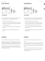
Specifications
Signal Connections
Control inputs 3 x 3.5 mm jacks,
summed
Impedance 100 kΩ unbalanced
CV range 1 V / octave,
+/-10 V maximum
External input 1 x 3.5 mm jack,
summed with CV inputs
Impedance 100 kΩ unbalanced
Attenuation -∞ to unity gain,
inverting and non
inverting
Control outputs 3 x 3.5 mm parallel jacks
Impedance 10 Ω unbalanced
Maximum output level +/-10 V
Controls
Control selectors 4 x sliding routing
switches
Attenuator Rotary knob, selectable
Power
Power supply Eurorack
Current draw 10 mA (+12 V),
10 mA (-12 V)
Physical
Dimensions 35 x 40 x 129 mm
(1.4 x 1.6 x 5.1")
Rack units 8 HP
Weight 0.09 kg (0.2 lbs)
Hereby, Music Tribe declares that this product is in compliance with Directive 2014/30/EU, Directive 2011/65/EU and Amendment
2015/863/EU, Directive 2012/19/EU, Regulation 519/2012 REACH SVHC and Directive 1907/2006/EC.
Full text of EU DoC is available at https://community.musictribe.com/
EU Representative: Music Tribe Brands DK A/S
Address: Gammel Strand 44, DK-1202 København K, Denmark
UK Representative: Music Tribe Brands UK Ltd.
Address: 8th Floor, 20 Farringdon Street London EC4A 4AB, United Kingdom
型号: 992 CONTROL VOLTAGES 合成器与采样器
制造商: Music Tribe Commercial MY Sdn. Bhd. –
Made in China 中国制造
CAN ICES–003 (B)/NMB–003 (B)
电源连接
安装
992 随附用于连接到标准 Eurorack 电源系统的所需电源线。 请按照以下步骤将电源连接到模块。 在将模块安装到机
架盒中之前, 进行这些连接会更容易。
1. 关闭电源或机架式机箱的电源, 然后断开电源线的连接。
2. 将电源线上的 16 针连接器插入电源或机架盒上的插座。该连接器具有一个卡舌, 该卡舌将与插槽中的间隙对
齐, 因此不会被错误地插入。 如果电源没有键控插座, 请确保将插针 1 (- 12 V) 的方向与电缆上的红色条纹对准。
3. 将 10 针连接器插入模块背面的插槽中。 连接器具有一个卡舌, 该卡舌将与插座对齐以正确定向。
4. 在牢固连接电源线的两端之后, 您可以将模块安装在盒中并打开电源。
模块随附了必要的螺钉, 用于将其安装在 Eurorack 箱中。 安装前, 请先连接电源线。
根据机架机箱的不同, 可能会有一系列沿机箱长度方向相距 2 HP 的固定孔, 或者是一条允许单个螺纹板沿机箱长度
方向滑动的导轨。 可以自由移动的螺纹板可以精确定位模块, 但是在安装螺钉之前, 应将每个板的位置与模块上的
安装孔大致成一定关系。
将模块靠在 Eurorack 导轨上, 以使每个安装孔都与螺纹导轨或螺纹板对齐。 从头开始固定螺丝, 在对齐时可以对位
置进行细微调整。 确定最终位置后, 拧紧螺钉。

We Hear You
-
 1
1
-
 2
2
-
 3
3
-
 4
4
-
 5
5
-
 6
6
-
 7
7
-
 8
8
-
 9
9
-
 10
10
-
 11
11
-
 12
12
-
 13
13
-
 14
14


Behringer 992 CONTROL VOLTAGES Guida Rapida
- Tipo
- Guida Rapida
in altre lingue
- français: Behringer 992 CONTROL VOLTAGES Guide de démarrage rapide
- español: Behringer 992 CONTROL VOLTAGES Guía de inicio rápido
- Deutsch: Behringer 992 CONTROL VOLTAGES Schnellstartanleitung
- Nederlands: Behringer 992 CONTROL VOLTAGES Snelstartgids
- português: Behringer 992 CONTROL VOLTAGES Guia rápido
- polski: Behringer 992 CONTROL VOLTAGES Skrócona instrukcja obsługi
- 日本語: Behringer 992 CONTROL VOLTAGES クイックスタートガイド